DOC NO.: DEC-SA-WI007
REV.: B/0
DATE: 2021/02/02
壓敏電阻器規格承認書
APPROVAL SPECIFICATION FOR VARISTORS
客戶
CUSTOMER
客戶料號
CUSTOMER P/N
客戶規格描述
CUST. DESCRIPTION
規格描述
DESCRIPTION
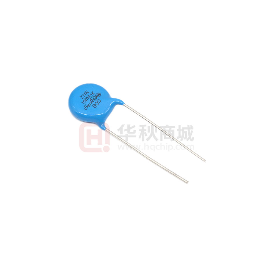
10D471K/F7.5/直脚/L24/环氧(蓝)/ZNR
產品編碼
PART NUMBER
RM10D471KD1IE100
日期
DATE
文件編號
DOC. NO.
2021/6/9
德爾創承認欄
APPROVED BY DERSONIC
批 准
APPROVED BY
審核
CHECK BY
制訂
FORMULATE BY
彭少雄
吳成愛
陳冬花
DEC-SA-WI007
客戶承認欄
APPROVED BY CUSTOMER
批 准
APPROVED BY
審核
CHECK BY
東莞市德爾創電子有限公司
DONGGUAN DERSONIC ELECTRONIC CO., LTD.
廣東省東莞市長安鎮錦廈河南工業區錦平路5號
No. 5, Jinping Rd., Jinxia Henan Industrial Zone, Changan Town,
®
ZNR Dongguan City, PRC.
FAX: +86-769-8155 5989
ZNRC ® TEL: +86-769-8155 5686
E-mail: sales@dersonic.com
/
quality@dersonic.com
Website: http://www.dersonic.com
�編號DOC NO.:
壓敏電阻器規格承認書
APPROVAL SPECIFICATION FOR VARISTORS
DEC-SA-WI007
版本REV.:
B/0
日期DATE:
2021/6/9
頁碼PAGE:
1 / 15
目
錄
CONENTS
1. 規格表
DATA SHEET
……………………………………………………………
2
2. 概述
INTRODUCTION
……………………………………………………………
3
3. 應用
APPLICATION
……………………………………………………………
4
……………………………………………………………
4. 基本特性
5
GENERAL CHARACTERISTIC
5. 名詞解釋
DEFINITIONS
……………………………………………………………
7
6. 產品編碼
PART NUMBER
……………………………………………………………
8
……………………………………………………………
7. 測量與試驗
9
MEASUREMENT AND TESTING
……………………………………………………………
8. 標誌說明
11
MARKING DESCRIPTION
……………………………………………………………
9. 安全注意事項
12
SAFETY PRECAUTIONS
……………………………………………………………
10. 編帶尺寸規格
15
TAPING SPECIFICATIONS
请确保我们的產品安装到您的產品上前,已根据您的需求进行了评估。
Please make sure that your product has been evaluated in view of your
specifications with our product being mounted to your product.
请您在使用我们的產品时,不要偏离此標准。
You are requested not to use our product deviating from this
specification.
�編號DOC NO.:
壓敏電阻器規格承認書
APPROVAL SPECIFICATION FOR VARISTORS
DEC-SA-WI007
版本REV.:
B/0
日期DATE:
2021/6/9
頁碼PAGE:
2 / 15
1. 規格表
DATA SHEET
本體顏色:
Body color:
包封層:
Coating:
導線:
Lead wire:
蓝色
Blue
环氧樹脂(UL94 V-0)
Epoxy resin (UL94 V-0)
CP線
CP wire
印字:
Marking:
ZNR
10D471K
**D
產品編碼
Part number
RM10D471KD1IE100
客戶料號
Customer P/N
最大連續工作電壓
Max continuous operating voltage
壓敏電壓, VN
Varistor voltage, VN
標稱脈衝電流, Ip
Nominal pulse current, Ip
最大抑制電壓, VC
Maximum clamping voltage, VC
耐衝擊電流
Withstanding
surge current
470V±10% @ 1mA 30ms
25A @ 8/20μs
775V (max) @ Ip
最大脈衝電流
Maximum pulse current
2500A (1 time) @ 8/20μs
1250A (2 times) @ 8/20μs (5 minute interval)
重複脈衝電流
Repetitive pulse current
750A (10 times), @ 8/20μs (90 sec. interval)
衝擊壽命
Impulse life
最大耐受能量
Maximum energy
額定功率
Rated power
最大漏電流
Maximum leakage current
最大電容量
Maximum capacitance
工作溫度範圍
Operating temperature range
D (Diameter)
T (Thickness)
H (Heitht)
尺寸
Dimensions
AC300V (max)
DC385V (max)
F (Lead spacing)
F1 (Lead malposed spacing)
L (Lead length)
ød (Lead diameter)
120A (10 000 times) @ 8/20μs (10 sec. interval)
67J @ 10/1000μs
0.4W
20μA @ 75% VN
210pF @ 1kHz 1.0Vrms
-40ºC~+85ºC
12.5mm max
4.1mm±0.8mm
16.5mm max
7.5mm±1.2mm
2.66mm±0.5mm
24mm±4.0mm
0.75mm±0.10mm
�編號DOC NO.:
壓敏電阻器規格承認書
APPROVAL SPECIFICATION FOR VARISTORS
DEC-SA-WI007
版本REV.:
B/0
日期DATE:
2021/6/9
頁碼PAGE:
3 / 15
2. 概述
INTRODUCTION
壓敏電阻是一種具有在一定的電壓條件下支援電流急速流出的電壓-電流特性的產品。
A varistor has the volt-ampere characteristics in which current suddenly starts to flow
through the device at a certain voltage.
壓敏電阻的作用:保護在電子線路中的電子元器件免受過電壓的影響。如下圖所示,壓敏電阻並聯在電
路中起保護作用。當有脈衝(脈衝電流Is:由脈衝電壓Vs和阻抗Zs決定)施加在電路上时,脈衝電流
(Is)限制脈衝電壓在壓敏電阻的限制電壓Vc之內。
The varistors are used to protect components in electronic and electric circuits from
overvoltage. As shown in following figure, a varistor is inserted in parallel with a
circuit to be protected. When a pulse is applied to the circuit, pulse current Is, which
is determined by pulse voltage Vs and pulse impedance Zs, flows to limit the pulse voltage
to the varistor limit voltage Vc.
壓敏電阻器對脈衝的吸收
PULSE ABSORPTION BY VARISTOR
相互的關係可以用下面的公式來解釋:
The relation can be expressed by the equations as follows:
Vs=Is×Zs+Vc
∴
Vc=Vs-Is×Zs
因為Vs遠遠大於Vc,脈衝電流Is可以用以下公式求得
The pulse current Is are easily obtained by the following equation because of Vs much
larger than Vc.
Is≈Vs÷Zs
所以,由於可承受電壓大於最大的限定電壓,電路可以長时間的免於脈衝電壓的損壞。
Thus, the circuit can be protected from being damaged by pulse voltages as long as it has
withstand voltage larger than the maximum limit voltage.
由於吸收異常電壓和電流脈衝的特性,壓敏電阻可非常高效的保護電子器件。
Owing to the characteristic, the varistors are extremely effective as protecting devices
of electronic and electric equipment by absorption of abnormal voltages and lightening
pulses.
�編號DOC NO.:
壓敏電阻器規格承認書
APPROVAL SPECIFICATION FOR VARISTORS
DEC-SA-WI007
版本REV.:
B/0
日期DATE:
2021/6/9
頁碼PAGE:
4 / 15
3. 應用
APPLICATION
■ 消費電子產品:電視機、音訊輸出設備、安全插座、機上盒等
Consumer electronics products: television, audio output device, safety plug, STB etc.
■ 工業產品:馬達、半導體元件、繼電器、電磁開關、電源線路、三相整流線路、自動控制線路等
Industrial products: motor, semiconductor component, relay, electromagnetic switch, power
circuit, three-phase rectifier circuit, automatic control circuit etc.
■ 通信設備:電話機、傳真機、交換機等
Communication equipment: Telephone, facsimile, exchanger etc.
■ 電腦:電腦、顯示器、印表機、掃描器、電源、電源適配器等
Computer: computer, displayer, printer, scanner, power supply, adapter etc.
■ 汽車電子產品
Automotive electronics products
適用範圍
APPLICATIONS SCOPE
主要用途
Recommended Applications
規格
Specifications
05D180K
05D220K
05D270K
05D330K
05D390K
05D470K
05D560K
05D680K
07D180K
07D220K
07D270K
07D330K
07D390K
07D470K
07D560K
07D680K
10D180K
10D220K
10D270K
10D330K
10D390K
10D470K
10D560K
10D680K
14D180K
14D220K
14D270K
14D330K
14D390K
14D470K
14D560K
14D680K
20D180K
20D220K
20D270K
20D330K
20D390K
20D470K
20D560K
20D680K
05D820K
用於電話,DC48V通信電路電線 05D101K
Telephone, communication line (DC48V) 05D121K
05D151K
07D820K
07D101K
07D121K
07D151K
10D820K
10D101K
10D121K
10D151K
14D820K
14D101K
14D121K
14D151K
20D820K
20D101K
20D121K
20D151K
05D181K
用於AC100V線與線間(如日本)
05D201K
AC100V line-line applications (Japan etc.)
05D221K
07D181K
07D201K
07D221K
10D181K
10D201K
10D221K
14D181K
14D201K
14D221K
20D181K
20D201K
20D221K
05D241K
用於AC100~120V線與線間(如日本、美國等)
05D271K
AC100V~120V, line-line applications (Japan, US etc.)
05D301K
07D241K
07D271K
07D301K
10D241K
10D271K
10D301K
14D241K
14D271K
14D301K
20D241K
20D271K
20D301K
用於AC100~120V線與線間,用於電話(應對250V絕緣阻抗測試) 05D331K
AC100V~120V, line-line applications, telephone line 05D361K
applications (for DC250V insulation resistance test) 05D391K
07D331K
07D361K
07D391K
10D331K
10D361K
10D391K
14D331K
14D361K
14D391K
20D331K
20D361K
20D391K
05D431K
用於AC200~220V線與線間、線與大地間
05D471K
AC200V~220V, line-line and line-ground applications
05D511K
07D431K
07D471K
07D511K
10D431K
10D471K
10D511K
14D431K
14D471K
14D511K
20D431K
20D471K
20D511K
用於AC240V線與線間、線與大地間(如英國、澳洲等) 05D561K
AC240V, line-line and line-ground applications (UK, 05D621K
Australia etc.) 05D681K
07D561K
07D621K
07D681K
10D561K
10D621K
10D681K
14D561K
14D621K
14D681K
20D561K
20D621K
20D681K
05D751K
07D751K
07D781K
07D821K
10D751K
10D781K
10D821K
14D751K
14D781K
14D821K
20D751K
20D781K
20D821K
10D911K
14D911K
20D911K
14D102K
14D112K
14D122K
14D142K
20D102K
20D112K
20D122K
20D142K
14D162K
14D182K
20D162K
20D182K
用於低壓電路,如用於保護半導體器件、汽車電子產品、DC48V
以下的繼電器與電磁閥、靜電放電設備、行動電話等
For the low voltage circuit, Such as for the protection
of semiconductor devices, automotive electronics, DC48V
following relays and solenoid valves, electrostatic
discharge equipment, mobile phones, etc.
用於AC380V線與線間、線與大地間
AC380V, line-line and line-ground applications
用於AC415V線與線間、線與大地間
AC415V, line-line and line-ground applications
用於AC480V線與線間、線與大地間
AC480V, line-line and line-ground applications
用於線與大地間(應對AC1200V耐壓測試)
line-ground applications (for AC1200V withstanding test)
10D102K
10D112K
�編號DOC NO.:
DEC-SA-WI007
版本REV.:
B/0
日期DATE:
2021/6/9
頁碼PAGE:
5 / 15
壓敏電阻器規格承認書
APPROVAL SPECIFICATION FOR VARISTORS
4. 基本特性
GENERAL CHARACTERISTIC
■ 特性表
Characteristic sheet
AC
DC
V
V
V
抑制電壓
Clamping
voltage
(VC)
@ Ip 8/20μs
V max
180K
15.8~20.7
11
14
36
220K
19.4~25.3
14
18
43
05D
1
125
50
4
0.01
270K
23.7~31.1
17
22
53
07D
2.5
250
125
10
0.02
330K
29.0~36.3
20
26
65
10D
5
500
250
20
0.05
390K
35.1~42.9
25
31
77
14D
10
1000
500
40
0.1
470K
42.3~51.7
30
38
93
20D
20
2000
1000
80
0.2
560K
50.4~61.6
35
45
110
680K
61.2~74.8
40
56
135
05D
1
250
100
10
0.01
820K
73.8~90.2
50
65
135
07D
2.5
500
250
20
0.02
101K
90~110
60
85
165
10D
5
1000
500
40
0.05
121K
108~132
75
115
200
14D
10
2000
1000
80
0.1
151K
135~165
95
125
250
20D
20
3000
2000
120
0.2
181K
162~198
115
150
300
201K
180~220
130
170
340
05D
5
600
200
17
0.1
221K
198~242
140
180
360
07D
10
1250
600
75
0.25
241K
216~264
150
200
395
10D
25
2500
1250
120
0.4
271K
243~297
175
225
455
14D
50
4500
2500
150
0.6
301K
270~330
195
250
505
20D
100
6500
4500
190
1
331K
297~363
210
275
545
361K
324~396
230
300
595
05D
5
800
400
22
0.1
391K
351~429
250
320
650
07D
10
1750
1200
100
0.25
431K
387~473
275
350
710
10D
25
3500
2500
150
0.4
471K
423~517
300
385
775
14D
50
6000
4500
200
0.6
511K
459~561
320
415
845
20D
100
10000
6500
250
1
531K
477~583
330
435
875
561K
504~616
350
460
915
07D
10
1800
1250
120
0.25
621K
558~682
385
505
1025
10D
25
4000
3000
175
0.4
681K
612~748
420
560
1120
14D
50
8000
6000
220
0.6
721K
648~792
440
585
1180
20D
100
13000
8000
260
1
751K
675~825
460
615
1240
781K
702~858
485
640
1290
10D
821K
738~902
510
670
1355
14D
911K
819~1001
550
745
1500
20D
951K
855~1045
575
765
1570
102K
900~1100
625
825
1650
K type: General type
112K
990~1210
680
895
1815
D type: Standard type
122K
1080~1320
750
1060
2000
T type: Hi-temperature (125ºC) type, based on D type
142K
1260~1540
880
1140
2310
V type: Hi-energy type
162K
1440~1760
940
1280
2640
J type: Withstanding surge type
182K
1620~1980
1000
1465
2970
Q type: Appendix Q (IEC 60950-1, 6KV/3KA)
壓敏電壓範圍
Varistor
壓敏
voltage
電壓
range
Varistor
(@ 1mA)
voltage
最大工作電壓
Max operating
voltage
等級電流
耐衝擊電流
Class
尺寸
Withstanding
impulse current
current
規格
(Ip)
Nominal
8/20μs
diameter @ 8/20μs
A
1 time
2 times 104 times
額定
功率
Rated
power
W
Varistor voltage: 180K ~ 680K (D, T type)
Varistor voltage: 180K ~ 680K (V type)
Varistor voltage: 820K ~ 182K (D, T, K type)
Varistor voltage: 820K ~ 182K (V type)
Varistor voltage: 391K ~ 112K (J type)
Varistor voltage: 391K ~ 182K (Q type)
25
4000
3000
175
0.4
50
8000
6000
220
0.6
100
13000
8000
260
1
Note:
�編號DOC NO.:
壓敏電阻器規格承認書
APPROVAL SPECIFICATION FOR VARISTORS
DEC-SA-WI007
版本REV.:
B/0
日期DATE:
2021/6/9
頁碼PAGE:
6 / 15
4. 基本特性
GENERAL CHARACTERISTIC
■ 符合RoHS 2.0、REACH及無鹵
Comply with rohs 2.0, reach, halogen-free available.
■ 安規認證
Safety certification
認證機構
CERTIFICATE
AUTHORITY
認證標准
APPROVAL STANDARD
證書編號
CERTIFICATE NO.
GB/T 10193-1997
GB/T 10194-1997
GB 4943.1-2011
GB 8898-2011
GB/T 10193-1997
GB/T 10194-1997
CQC
TÜV SÜD
UL
(cUL)
EC 61051-1:2018
IEC 61051-2:1991/A1:2009
IEC 61051-2-2:1991
認證範圍
CERTIFICATION RANGE
規格
SPECS
壓敏電壓
VARISTOR
VOLTAGE
最大連續交流電壓
MAXIMUM CONTINUOUS
OPERATING VOLTAGE A.C.
CQC14001104814
07D
18V-820V
11VAC-510VAC
CQC16001149384
10D
18V-1100V*
11VAC-680VAC
CQC16001149385
14D
18V-1800V*
11VAC-1000VAC
CQC16001149386
20D
18V-1800V*
11VAC-1000VAC
07D
18V-820V
10VAC-510VAC
10D
18V-1100V
10VAC-680VAC
14D
18V-1800V
10VAC-1000VAC
20D
18V-1800V
10VAC-1000VAC
07D
18V-820V
11VAC-510VAC
10D
18V-1100V
11VAC-680VAC
14D
18V-1800V
11VAC-1000VAC
20D
18V-1800V
11VAC-1000VAC
B 096835 0001**
UL 1449 (4th edition)
E485399
*: 18V~360V is only applicable to GB/T 10193-1997, GB/T 10194-1997
**: Additional test for 10D, 14D, 20D series: Annex Q of IEC 60950-1:2005/A2:2013, clause 14.13 of IEC
60065:2014 and clause G.8.1 of IEC 62368-1:2018.
■ 典型的10D471K抑制電壓特性曲線(供參考)
Typical 10D471K clamping voltage characteristic curve (for reference)
抑制電壓區域
CLAMPING VOLTAGE AREA
漏電流區域
LEAKAGE CURRENT AREA
5000
Voltage
(V)
500
50
1μA
10μA
0.1mA
1mA
10mA
0.1A
1A
10A
100A
1kA
10kA
Current
�Current
編號DOC NO.:
壓敏電阻器規格承認書
APPROVAL SPECIFICATION FOR VARISTORS
DEC-SA-WI007
版本REV.:
B/0
日期DATE:
2021/6/9
頁碼PAGE:
7 / 15
■ 工作溫度降額曲線(見下圖)
Operating temperature derating curve (see fig below)
请注意:額定特性包括最大連續工作電壓、耐衝擊電流、能量耐量及額定功率,降幅2.5%/ºC
Please note: rated characteristic includes maximum continuous operating voltage,
withstanding surge current, maximum energy and rated dissipation power, 2.5%/ºC
reduction.
■ 壓敏電壓溫度係數
0 to -0.05 %/ºC max.
Temperature coefficient of varistor voltage:
■ 儲存溫度範圍
-55ºC~+125ºC
Storage temperature range:
■ 絕緣電壓
2500V 60s (body Insulation)
Insulation voltage:
5. 名詞解釋
DEFINITIONS
1) 最大連續工作電壓:在环境溫度25ºC下,允許連續施加在壓敏電阻器上的最大工頻正弦電壓有效值Uac(總
諧波失真小於5%)或直流電壓值Udc。
Maximum continuous operating voltage: maximum ac RMS voltage Uac or maximum dc voltage Udc
which can be applied continuously at a temperature of 25ºC. Uac shall be a substantially
sinusoidal voltage (less than 5% total harmonic distortion).
2) 壓敏電壓:直流參考電流流過壓敏電阻器时,壓敏電阻器兩端的直流電壓值。
Varistor voltage: dc voltage across the varistor when the dc reference current flows through
the varistor.
3) 標稱脈衝電流:是一個電流峰值,它是以每分鐘2次的方式用8/20μs脈衝電流衝擊100次,壓敏電阻器可以
通過的電大峰值電流的1/10。
Nominal pulse current: it is a current peak value. It is pulsed 100 times with 8/20μs pulse
current in 2 times per minute, and the varistor can pass 1/10 of the peak current.
4) 抑制電壓:是指在標准大氣條件下,壓敏電阻器中通過標稱脈衝電流时,其兩端呈現的電壓峰值。
Clamping voltage: refers to the voltage peak appearing between the two terminals of a
varistor when passing a nominal pulse current under standard atmospheric conditions.
5) 耐衝擊電流:壓敏電阻器允許通過的規定波形的每個脈衝的最大電流值。
Withstanding surge current: the maximum current value of each pulse of the specified waveform
that the varistor is allowed to pass.
6) 能量耐量:能被壓敏電阻器吸收指定波形的最大單個脈衝能量,除非另有規定應使用10/1000μs脈衝。
Maximum energy: the maximum single pulse energy of the specified waveform that can be
absorbed by the varistor. Unless otherwise specified, 10/1000μs pulses should be used.
7) 額定功耗:在25℃的环境溫度下的最大允許功耗。
Rated power: the maximum allowable power dissipation of varistors at an ambient temperature
of 25ºC.
8) 漏電流:在25℃或規定的其他溫度下,施加最大直流電壓时,通過壓敏電阻器中的電流。
Leakage current: the current through the varistor at the maximum dc voltage applied at 25ºC
or other specified temperature.
�編號DOC NO.:
壓敏電阻器規格承認書
APPROVAL SPECIFICATION FOR VARISTORS
DEC-SA-WI007
版本REV.:
B/0
日期DATE:
2021/6/9
頁碼PAGE:
8 / 15
6. 產品編碼
PART NUMBER
RM
10
D
系列
Series
標稱直徑
Nominal
diameter
形狀
Shape
序號
No.
471
K
壓敏電壓
誤差
Varistor Tolerance
voltage
2
標稱直徑
Nominal diameter
3
形狀
Shape
4
壓敏電壓
Varistor voltage
5
誤差
Tolerance
6
脚距
Lead spacing
9
脚型
Lead style
編帶包装或散装脚長
Taping packing or Lead length
(bulk)
包封材質
Coating material
10
I
E
編帶包装
包封材質
或散装脚長
Coating
Taping packing material
or Lead length
(bulk)
表達內容
Expression
系列
Series
8
1
脚型
Lead
style
名稱
Field name
1
7
D
脚距
Lead
spacing
類別和標誌
Type and marking
RM:
壓敏電阻器
ZnO (Zinc oxide) Varistors
10: 10mm
D:
圆形
Disc
471: 470V
K: ±10%
D: F=7.5mm
1:
直脚
Straight Leads
I:
散件包装, 脚長(L)=24mm
Bluk packing, Lead length (L)=24mm
E:
环氧(蓝)
Epoxy (Blue)
標准型,打印ZNR商標
100: Standard type, printed ZNR trademark
常用標稱直徑有:
Common nominal diameters are: 5mm, 7mm, 10mm, 14mm, 20mm
常用壓敏電壓有:
Common varistor voltage are: 18V, 22V, 27V, 33V, 39V, 47V,
56V, 68V, 82V, 100V, 120V, 150V, 180V, 200V, 220V, 240V,
270V, 300V, 330V, 360V, 390V, 430V, 470V, 510V, 560V,
620V, 680V, 750V, 780V, 820V, 910V, 1000V, 1100V, 1200V,
1800V.
編帶包装方式示意圖
TAPING PACKAGING DIAGRAM
卷圆盤包装
REEL PACKING
脚型示意圖
LEAD STYLE DIAGRAM
折疊包装
AMMO PACKING
直脚
STRAIGHT LEAD
外彎脚
OUTSIDE KINK LEAD
平行脚
VERTICAL KINK LEAD
100
類別和標
誌
Type and
marking
�編號DOC NO.:
壓敏電阻器規格承認書
APPROVAL SPECIFICATION FOR VARISTORS
DEC-SA-WI007
版本REV.:
B/0
日期DATE:
2021/6/9
頁碼PAGE:
9 / 15
7. 測量與試驗
MEASUREMENT AND TESTING
如無特殊需要,壓敏電阻器應在下列环境條件下进行試驗:
If there is no special need, varistor measurement and testing should be conducted under
the following environmental conditions:
溫度
Temperature
相對濕度
Relative humidity
大氣壓力:
Atmospheric pressure:
25ºC±5ºC
30%~70%
86kpa~106kpa
序號
No.
檢驗項目
Item
要求
Specification
試驗方法
Testing method
1
外觀與尺寸
Appearance
And dimension
外觀形狀沒有明顯的缺點,尺寸在標准
範圍內。
No marked defect on appearance form
and dimensions are within specified
range.
壓敏電阻器必須用目視檢查其明顯的缺點。
The varistors should be visually inspected for evidence
of defect.
尺寸用遊標卡尺測量。
Dimensions should be measured with slide calipers.
2
標誌
Marking
清晰易於識別。
To be easily legible.
目視檢查。
The capacitor should be visually inspected.
3
抑制電壓
Clamping voltage
滿足額定值
To meet the specified value.
使用波形為8/20μs的標稱脈衝電流施加在壓敏電阻器引出端
上,同时測試抑制電壓的峰值。
A nominal pulse current of 8/20μs waveform was applied
to the varistor terminals and the clamping voltage peak
was tested.
4
壓敏電壓
Varistor voltage
在誤差範圍內。
Within specified tolerance.
將壓敏電阻器固定在無銹蝕的夾具上,按“規格表”規定的條
件进行測試壓敏電阻器引出端的電壓。
The varistor is fixed on the fixture without rust, and
the voltage of the varistor terminal is tested
according to the conditions specified in the "Data
sheet".
5
電容量
Capacitance
滿足額定值
To meet the specified value.
在標准大氣條件下,使用1kHz、1V的條件进行測量。
Measurement at 1kHz, 1V under standard atmospheric
conditions
6
漏電流
Leakage current
滿足額定值
To meet the specified value.
在25ºC时施加75%的最大連續直流電壓,測量其漏電流。
Apply a maximum continuous dc voltage of 75% to the
varistor at 25ºC and measure its leakage current.
7
8
9
試驗過程中壓敏電阻器應無擊穿、閃
絡,外觀不應有任何機械損傷
The varistor should have no
電流衝擊
breakdown or flashover during the
穩定性
test, and the appearance should not
Impulse
have any mechanical damage
testing
方波電流 衝擊後,應在常溫下恢復2h,測量壓敏
stability
Square 電壓,其值相對於初始值的變化率應小
於10%
wave
current After the impulse, it should be
stored at room temperature for 2
hours. Measure the varistor
最大脈衝電流
voltage. The rate of change should
Max pulse current be less than 10% of the initial
value.
重複脈衝
電流
Repetitiv
e pulse
current
耐電壓
Withstand voltage
在8/20μs波形下,對壓敏電阻器施加10次重複脈衝電流,每個
方向衝擊各5次,相鄰兩次衝擊的間隔為90s。
Under 8/20μs waveform, the varistor was subjected to
10 times of repetitive pulse current, and the impulses
was 5 times in each direction. The interval between two
adjacent impulses was 90 s.
對壓敏電阻器施加1次方波電流衝擊(2ms或者10/1000μs)的衝
擊,方向任意。
The varistor is subjected to a square wave current
impulse (2ms or 10/1000μs), in any direction.
在8/20μs波形下,對壓敏電阻器施加1次最大脈衝電流衝擊,
方向任意。
Under 8/20μs waveform, the varistor is subjected to a
max pulse current impulse, in any direction.
首先,將壓敏電阻器的端子擰在一起,然後將金屬箔包住壓敏
電阻器离端子3-4mm的本體,接著將壓敏電阻器插入盛著直徑為
試驗過程中壓敏電阻器無擊穿、電弧、
1mm的金屬球的容器中,最後施加2500V的電壓60秒種。
閃絡等現象,外觀不應有任何機械損傷
First, the terminals of the varistor should be
The varistor should have no
connected together. Then, a metal foil should be
breakdown, arcing or flashover
closely wrapped around the body of the varistor to the
during the test, and the appearance
distance of about 3 to 4mm from each terminal. Then,
should not have any mechanical
the varistor should be inserted into a container filled
damage.
with metal balls of about 1mm diameter. Finally, 2500v
voltage is applied for 60 sec. Between the varisor lead
�編號DOC NO.:
壓敏電阻器規格承認書
APPROVAL SPECIFICATION FOR VARISTORS
DEC-SA-WI007
版本REV.:
B/0
日期DATE:
2021/6/9
頁碼PAGE:
10 / 15
續上表
Continued on the table
序號
No.
檢驗項目
Item
10
最大能量
Maximum energy
11
衝擊壽命
Impulse life
要求
Specification
滿足額定值
To meet the specified value.
在10/1000μs電流波下,壓敏電阻器能承受的最大能量。
The maximum energy that the varistor can absorb under
the 10/1000μs current wave.
試驗後壓敏電阻器外觀不應有任何機械
損傷,壓敏電壓變化率不應超過10%
After the test, the appearance of
the varistor should not have any
mechanical damage, and the varistor
voltage change rate should not
exceed 10%
常室溫下,將指定的脈衝電流間隔10秒接通10000次,在1小时
至2小时时間段內測定其特性。
The change of varistor voltage shall be measured after
the specified impulse current is applied 10000 times
continuously with the interval of 10 seconds at room
temperature.
在环境溫度25ºC下施加連續脈衝電流时,壓敏電阻器可以耗散
的最大平均功率。
Maximum allowable average power dissipation when
subjected to the stress of successive impulses and at
the temperature of 25ºC.
12
額定功率
Rated power
滿足額定值
To meet the specified value.
13
壓敏電壓溫度係數
Temperature
coefficient of
varistor voltage
滿足額定值
To meet the specified value.
14
15
16
17
18
試驗方法
Testing method
式中,VN1是25ºC下的壓敏電壓值,VN2是85ºC下的壓敏電壓值
Where VN1 is varistor voltage at 25ºC and VN2 is
varistor voltage at 85ºC
導線無折斷,壓敏電阻器無破損。
Lead wire should not be cut off.
Varistor should not be broken.
固定壓敏電阻器的本體,使壓敏電阻器每支導線均承受
10N(1.0mm導線直徑為20N)垂直力,保持10±1秒鐘。
Fix the body of the varistor and apply a tensile weight
gradually to each lead wire in the radial direction of
the capacitor up to 10N (1.0mm lead wire diameter is
20N) and keep it for 10±1 s.
導線抗折強度
Terminal bending
strength
導線無折斷,壓敏電阻器無破損。
Lead wire should not be cut off.
Varistor should not be broken.
壓敏電阻器導線應承受5N(1.0mm導線直徑為10N)重量,然後向
外彎折成90º,然後回復到原來位置;接著往反方向彎折90º,
再復原;彎折一次2-3秒鐘。
Each lead wire should be subjected to 5N (1.0mm lead
wire diameter is 10N) weight and then a 90º bend, at
the point of egress, in one direction, return to
original position, and then apply a 90º bend in the
opposite direction at the rate of one bend in 2 to 3 s.
可焊性
Solderability of
leads
導線必須有3/4以上的面積均勻附著焊錫
。
Lead wire should be soldered with
uniform coating on the axial
direction over 3/4 of the
circumferential direction.
將壓敏電阻器的導線浸入焊料中2±0.5秒鐘,浸入深度离導線
根部1.5-2.0mm。
The lead wire of a varistor should be dipped into
molten solder for 2±0.5 s. The depth of immersion is
up to about 1.5 to 2.0mm from the root of lead wires.
焊錫溫度:245±5ºC
Temp. of solder: 245±5ºC
耐焊接熱
Soldering effect
試驗後壓敏電阻器外觀不應有任何機械
損傷,壓敏電壓變化率不應超過5%
After the test, the appearance of
the varistor should not have any
mechanical damage, and the varistor
voltage change rate should not
exceed 5%.
導線浸入离導線根部1.5-2.0mm處、錫溫為260±5ºC錫槽中10±
1秒。試驗後,壓敏電阻器應在室溫中恢復2小时。
The lead wires should be immersed in solder of 260±5ºC
up to 1.5 to 2.0mm from the root of terminal for 10±
1.0 s. After the test, the varistor should recover at
room temperature for 2h.
試驗後壓敏電阻器外觀不應有任何機械
損傷,壓敏電壓變化率不應超過5%
After the test, the appearance of
振動
the varistor should not have any
Vibration resistance
mechanical damage, and the varistor
voltage change rate should not
exceed 5%.
將壓敏電阻器導線焊穩和調整振動頻率範圍為10-55Hz、總振幅
為1.5mm,振動從10Hz到55Hz,然後再回到10Hz,大約一分鐘。
總时間六個小时,每兩小时在相互垂直方向來回三次。
The varistor should be firmly soldered to the
supporting lead wire and vibrated at a frequency range
of 10 to 55Hz, 1.5mm in total amplitude, with about a 1
minute rate of vibration change from 10Hz to 55Hz and
back to 10Hz. Apply for a total of 6h., 2h each in 3
mutually perpendicular directions.
導線抗張強度
Terminal tensile
strength
�編號DOC NO.:
壓敏電阻器規格承認書
APPROVAL SPECIFICATION FOR VARISTORS
DEC-SA-WI007
版本REV.:
B/0
日期DATE:
2021/6/9
頁碼PAGE:
11 / 15
續上表
Continued on the table
序號
No.
19
20
21
22
檢驗項目
Item
要求
Specification
試驗方法
Testing method
耐濕負荷
Humidity loading
試驗後壓敏電阻器外觀不應有任何機械
損傷,壓敏電壓變化率不應超過10%
After the test, the appearance of
the varistor should not have any
mechanical damage, and the varistor
voltage change rate should not
exceed 10%.
壓敏電阻器保持在溫度為40±2ºC、相對濕度為90%-95%條件下
施加最大連續交流電壓500±12小时。
Apply the max continuous operating ac voltage for 500±
12 h. At 40±2ºC in 90% to 95% relative humidity.
試驗結束後,壓敏電阻器應在室溫下恢復2小时。
After the test, the varistor should recover at room
temperature for 2h.
高溫負荷
High temperature
loading
試驗後壓敏電阻器外觀不應有任何機械
損傷,壓敏電壓變化率不應超過10%
After the test, the appearance of
the varistor should not have any
mechanical damage, and the varistor
voltage change rate should not
exceed 10%.
應給壓敏電阻器施加最大連續交流電壓,儲存最高工作溫度下
1000±12小时。
The maximum continuous ac voltage should be applied to
the varistor and stored at a maximum operating
temperature of 1000 ±12 h
試驗結束後,壓敏電阻器應在室溫下恢復2小时。
After the test, the varistor should recover at room
temperature for 2 h.
溫度迴圈
Temperature cycle
溫度迴圈試驗按以下條件进行試驗和測量
Temperature cycling shall be measured in the following
試驗後壓敏電阻器外觀不應有任何機械 test.
損傷,壓敏電壓變化率不應超過10%
Step
Temperature
Time
After the test, the appearance of
1
-40±2ºC
30min
the varistor should not have any
2
+125±2ºC
30min
mechanical damage, and the varistor 迴圈次數:5次
voltage change rate should not
Cycle numbers: 5 cycles
exceed 10%
試驗結束後,壓敏電阻器應在室溫下恢復2小时。
After the test, the varistor should recover at room
temperature for 2 h.
按[IEC 60695-11-5]對MOV进行針狀火焰試驗。火焰施加部位為
火焰撤去後30秒內,燃燒應能自熄
電阻體樣品的側面,施加时間為5秒。
阻燃性
The burning of the sample shall be
The MOV shall be subjected to the needle-flame test of
Passive flammability self-extinguishing within 30 s
[IEC 60695-11-5]. The needle-flame application shall be
after removing the needle flame.
on the side surface of the samples for 5 s.
8. 標誌說明
MARKING DESCRIPTION
公司商標
Company trademark
德爾創商標:
Dersonic's trademark:
ZNR
ZNRC
壓敏電阻規格
Varistor specifications, ex.: 20,
D,
511,
K,
Nominal chip diameter 20mm
disc chip,
varistor voltage 510V (51×101)
varistor voltage tolerance ±10%
安規標誌
Safety certification marking
生產週期和內部識別碼
Production cycle and internal identification code, ex.:
A
生產年份
Production year
A, 2020
B, 2021
︙
Z, 2045
A, 2046
9
生產月份
Production month
1, Jan. ; 2, Feb.;
︙
9, Sept.; O, Oct.;
N, Nov.;
D, Dec.
Q
識別碼
Production ID
D, Standard type;
K, General type
T, Hi-temperature (125ºC) type;
V, Hi-energy type;
J, Withstanding surge type (07D, 2.5kV/40 times; 10D, 4kV/40 times);
Q, Appendix Q (IEC 60950-1, 6KV/3KA) type
�編號DOC NO.:
壓敏電阻器規格承認書
APPROVAL SPECIFICATION FOR VARISTORS
DEC-SA-WI007
版本REV.:
B/0
日期DATE:
2021/6/9
頁碼PAGE:
12 / 15
9. 安全注意事項
SAFETY PRECAUTIONS
9.1.
使用壓敏電阻器时,壓敏電阻器周圍條件(設備設計中的材料、环境、電源條件、電路條件等)發生異常时,則可能引發火災、觸電、燒傷、以及
產品故障。
In case that a varistor is used, if an abnormality takes place because of peripheral conditions of the varistor(material,
environments, power source conditions, circuit conditions, etc. In equipment design), fire, electric shock, burn, or product
failure may be occur.
下列內容為使用时的相關注意事項,请認真确認後再行使用。如對未及事項有疑議,请速與我公司擔當部門聯繫。
The precautions for this product are described below; understand the content thoroughly before usage. For more questions,
contact us.
嚴格遵守事項
Precautions to be strictly observed
9.1.1. 額定性能确認
Confirmation of performance ratings
请遵守壓敏電阻器的最大連續工作電壓,耐衝擊電流、最大能量耐量、浪湧壽命、額定功率和操作溫度範圍等額定性能的規定,在規定範圍內使用
。
Use the varistor within its rated range of performance such as the maximum continuous operating voltage, withstanding surge
current, maximum energy, impulse life, rated power and operating temperature range.
超出規定範圍使用,則會造成壓敏電阻器性能劣化,破壞元件,嚴重可引起壓敏電阻器冒煙或起火。
If used outside the range, the varistor can be degrade and have element fracture, which may result in smoking and ignition.
9.1.2. 為避免意外現象發生,请採用如下對策
To avoid accidents due to unexpected phenomena, take the following measures
1) 壓敏電阻器受損时 ,可能出現破碎飛散,因此要對整合式產品加保護蓋或外盒。
In the event of fracture of the varistor, its pieces may scatter; hence, put the case or cover of the set product in place.
2) 请勿安装在可燃物品(塑膠電線、樹脂合成物等)附近。若無法避免,请使用不燃性保護外殼。
Do not install the varistor near combustible substances (polyvinyl chloride wires, resin moldings, etc.). If it’s difficult
to do, install a nonflammable cover.
3) 線間使用
Across-the-line use
線上間使用时,將保險絲與壓敏電阻器串聯。
When the varistor is used across a line, put a current fuse in series with the varistor.
4) 線-地間使用
Use between line to ground
a) 線上-地間使用时,壓敏電阻器短路时會產生接地電阻,電流保險絲不會熔斷,可能引起壓敏電阻器外塗層樹脂冒煙或起火。
If the case that the varistor is used between a line to the ground, the short circuit of the varistor may not blow the
current fuse because of grounding resistance, which may cause smoking and ignition of the varistors exterior resin.
為避免上述情況,请在電源端安装漏電斷路器。如無漏電斷路器,則需將電流保險絲與溫度保險絲串聯使用。
As the measure against it, install an earth leakage breaker on the power supply side of the varistor position. If no
earth leakage breaker is installed, use a thermal fuse together with a current fuse in series.
b) 在帶電部件與金屬部件之間使用壓敏電阻器时,壓敏電阻器短路时有觸電危險,故请將金屬部件接地或勿與人體接觸。
If the case that the varistor is used between a live parts to metal case, an electric shock may develop at a shortcircuit
of the varistor; hence, ground the metal case to the ground or keep it from the human body.
9.2.
使用注意事項
Application notes
9.2.1. 注意下列事項,可能導致壓敏電阻器壽命縮短或引發故障
Pay attention to the following items to avoid the shortened life and failure of the varistor.
1) 電路條件
Circuit conditions
a) 選定的壓敏電阻器的電壓最大值在最大連續工作電壓值之上。
Select a varistor of which the maximum voltage including fluctuations in source voltage allows for the maximum
permissible circuit voltage.
b) 短間隔性地施加浪湧时(施加抗干擾類比試驗電壓时),不可超過壓敏電阻器的額定功率。
In cases that surges are intermittently applied at short intervals (for example, in case that the voltage of the noise
simulator test is implemented etc.), do not let them exceed the varistors rated power.
c) 選定壓敏電阻器时,須按照表1的標准產品型號
Select a varistor recommended in table 1.
① 線間使用
Across-the-line use
單相三線式連線时單獨配線負荷導致負荷不平衡、電壓線和中性線短路、中性線欠損、容量性負荷情況下開閉时的共振等,將導致電源電
壓的上升,可能使用表1中標有*的產品型號。
If possible, use a part no. Marked with ✽ in case of voltage temporarily rises load unbalance of separately-wired
loads, short between hot and neutral-line, open of neutral line in single-phase-three-wired system, and due to
resonance at switching for a capacitive, inductive load.
② 線-地間使用
Used between line to ground
出現故障时,對地電壓將上升,因此,请使用附表1中推薦的產品型號。
Use a different part no. From “across-the-line use” as table 1, because of raising voltage in case of “line to
ground fault”.
�編號DOC NO.:
壓敏電阻器規格承認書
APPROVAL SPECIFICATION FOR VARISTORS
DEC-SA-WI007
版本REV.:
B/0
日期DATE:
2021/6/9
頁碼PAGE:
13 / 15
表1 – 壓敏電阻器的適用範例
Table 1 - example of varistor application
類別
Type
線間使用
Across-the-line use
線-地使用
Use between line to ground
DC / AC單相
DC/AC single-phase
AC三相
AC 3-phase
連線舉例
Connections example
MOV
壓敏電阻
選型舉例
Example of
varistor
電源電壓
Source voltage
壓敏電阻
Varistor
AC100V
201 ~ 361✽
AC120V
241 ~ 431✽
AC200V
431 ~ 561✽
AC220V
471 ~ 621✽
AC240V
511 ~ 621✽
AC380V
821
MOV1
MOV3
MOV
電源電壓
Source voltage
壓敏電阻
Varistor
AC100V
AC220V
471, 511, 621✽,
821✽✽, 182✽✽✽
AC230V
AC240V
511, 621✽,
821✽✽, 182✽✽✽
AC380V
112✽✽
182✽✽✽
MOV2
MOV4
进行設備的絕緣電阻試驗(DC500V)时,请使用表1中推薦的標有✽✽的產品型號。使用不可清除絕緣性能試驗的壓敏電阻電壓时,在一定
的電路條件下,試驗时可將壓敏電阻器從電路上取下。
Use a varistor marked with ✽✽ in table 1, in case of the insulation resistance test (500Vdc) for equipment. When
using a part of the varistor voltage that the insulation efficiency examination can not be cleared, there is a case
where the varistor can be done by removing it from the circuit depending on the circuit condition.
进行設備的耐電壓試驗(AC1000V或AC1200V)时,请使用表1中推薦的標有✽✽✽的產品型號。
Use a varistor marked with ✽✽✽ in table 1, in case of the withstanding voltage test (1000Vac or 1200Vac) for
equipment.
d) 關於電流保險絲
Concerning current fuse
① 所用壓敏電阻器與電流保險絲的額定電流,一般推薦按下表进行選定。此外,在用戶端,當壓敏電阻器損壞时,确認其設備是否會發生2次
傷害。
We recommend selecting a varistor and the rated current of a current fuse as follows. Finally, please be sure that
there is no danger if the varistor mounted on the equipment breaks.
規格specs
05D
07D
10D
14D
20D
保險絲額定電壓
Fuse rated current
≤2A
≤5A
≤5A
≤10A
≤10A
② 保險絲的插入部位建議按表1操作。
The recommended fuse position is shown in table 1.
e) 溫度保險絲
Concerning thermal fuse
將壓敏電阻器與溫度保險絲連接时,使用者端请儘量選用熱結合較好的保險絲。
Set a thermal fuse to get high thermal conductivity with varistor.
9.2.2. 使用环境
Operating environments
1) 壓敏電阻器不可在室外使用。
The varistor is designed to be used indoors. Do not use it exposed outdoors.
2) 不可在陽光直射場所、發熱源附近或溫度超過使用溫度範圍的場所使用。
Do not use the varistor in places exposed to temperatures beyond the operating temperature range, such as places exposed to
sunlight and vicinities of heating equipment.
3) 不可在淋雨、蒸汽、高濕度的場所使用。
Do not use the varistor in places exposed to high temperatures and high humidity, such as places exposed directly to rain,
wind, dew condensation, and vapor.
�編號DOC NO.:
壓敏電阻器規格承認書
APPROVAL SPECIFICATION FOR VARISTORS
DEC-SA-WI007
版本REV.:
B/0
日期DATE:
2021/6/9
頁碼PAGE:
14 / 15
4) 不可在粉塵或鹽分較多的場所以及被腐蝕性氣體污染的环境中使用。
Do not use the varistor in dusty and salty places and atmospheres polluted by corrosive gases.
9.2.3. 加工條件
Processing conditions
1) 不可採用可能導致外塗層樹脂劣化的溶劑(稀釋劑、丙酮等)进行清洗。
Do not wash the varistor by such solvents (thinner, acetone, etc) as its exterior resin deteriorates.
2) 不可施加可能導致外塗層樹脂或元件出現破損的衝擊或撞擊、壓力。
Do not apply a strong vibration or shock (by falling, etc) to the varistor, cracking to its exterior resin and element may
occur.
3) 將壓敏電阻器进行樹脂鍍膜(含護膜塑模)时,不可使用可能導致壓敏電阻器劣化的樹脂。
When coating the varistor with resin (including molding), do not use such resin.
4) 壓敏電阻器外塗層樹脂附近的引線部位不可进行強烈折彎或施加外力。
Do not bend the varistor lead wires at the position close to its varistor exterior resin, or apply external force to the
position.
5) 焊接时,请在如下條件下进行。且不可將構成壓敏電阻器的焊接部位或絕緣材料熔化。
When soldering the varistor lead wires, follow the recommended conditions and do not melt the solder and insulating materials
constituting the varistor.
焊接方式
推薦條件
注意事項
Soldering method
Recommended condition
Attention item
波峰焊
Flow soldering
260ºC, 10秒以內
260ºC, within 10 sec
引線型不是回流焊物件產品
Lead wires type is not reflow soldering
object part.
上述以外的條件下使用时,请用戶端自行确認。
For use other than the above conditions, please the client to confirm.
僅限进行1次返工,烙鐵溫度350ºc以下,时間控制在5秒以內。
Only 1 times rework, soldering iron temperature should not exceed 350ºc and should not be
applied for more than 5 sec.
■ 推薦焊接條件
Soldering temperature-time profile to recommend
9.2.4. 長期保管
Long-term storage
1) 壓敏電阻器不可保存在高溫、高濕場所。保存場所室溫40 ºC以下,濕度75%RH以下,保存期限為1年。
Do not store the varistor under high temperature and high humidity. Store it at a temperature up to 40 ºC and at humidity
below 75% RH, and use it within 1 year.
長期間保管(1年以上)时,使用时请确認產品的可焊性。
Before using the varistor that has been stored for a long period (1 years or longer), confirm the solderability.
2) 不可保存在腐蝕性氣體(硫化氫、亞硫酸、氯氣、氨氣等)环境中。
Avoid atmospheres full of corrosive gases (hydrogen sulfide, sulfurous acid, chlorine, ammonia, etc).
3) 保存場所避免陽光直射、結露等。
Avoid direct sunlight and dew condensation.
9.3.
說明
Notices
用於可靠性要求極高的設備(航空航太設備、醫療設備等)时,请事先至本公司諮詢使用型號和保護措施等相關事宜。
In cases that the varistor is used in equipment (aerospace equipment, medical equipment, etc) requiring extremely high
reliability, ask us for a selection of part no., and protection coordination, etc in advance.
若未按照產品規格書記載事項进行操作,並由此導致出現異常时,本公司不負任何責任。
Note that we do not take any responsibility for faults and abnormalities resulting from the use not in conformity with the
contents of entries in the delivery specification.
出現使用電路電壓的異常上升、超高浪湧的侵入等不可預期因素时,可能導致壓敏電阻器起火。為防止延燒到使用設備上,外部結構材料需使用阻
燃材料进行多重保護。
There is a possibility that the varistor will unexpectedly cause smoke or ignite because of an abnormal rise of the circuit
voltage and invasion of excessive surge. To prevent that accident from spreading over the equipment and not to expand the
damage, use multiplex protection such as the adoption of frame-retardant materials for housing parts and structural parts.
�方式一 Method 1
■
方式二 Method 2
孔距(P0)為12.7mm,元件間距离(P)為25.4mm
Feed hole pitch (P0) with 12.7mm and components pitch (P) with 25.4mm
■
孔距(P0)與元件間距离(P)均為12.7mm
或者,孔距(P0)與元件間距离(P)均為15.0mm
12.7mm by feed hole pitch (P0) and components pitch (P)
or, 15.0mm by feed hole pitch (P0) and components pitch (P)
10. 編帶標准
TAPING SPECIFICATIONS
版本REV.:
B/0
日期DATE:
2021/6/9
頁碼PAGE:
15 / 15
壓敏電阻器規格承認書
APPROVAL SPECIFICATION FOR VARISTORS
DEC-SA-WI007
編號DOC NO.:
进料孔與元件間距离
Hole center to component center
導線直徑
Lead wire diameter
紙帶寬
Tape width
膠帶寬
Hold-down tape width
孔位
Hole position
膠帶位置
Hold-down tape position
元件總高度
Component height
进料孔直徑
Feed hole diameter
編帶厚度
Total tape thickness
編帶總厚度(含導線)
Total tape, tape and lead wire
剪切長度
Snipped length
塗装脚長度
Coating rundown on leads
彎脚架高
Height of kink
P1
P2
Φd
W
W0
W1
W2
H
H0
H1
D0
t1
t2
L
C
K
12.7 15.0 25.4 25.4
12.7 15.0 12.7 12.7
3.85 3.75 3.85
6.35
0.7
18.0
7.0
9.0
3.0
18.0
16.0
40.0
4.0
0.9
1.7
11.0
3.0
5.0
7.7
---
±0.8
±1.0
±0.3
±0.7
±1.3
±0.1
+1.0
-0.5
min
+0.75
-0.5
max
+2.0
-0
±0.5
max
±0.3
max
max
max
max
max
彎脚類
元件到紙帶中心的高度 Kink lead type
Height of component
直脚類
from tape center
Straight lead
进料孔與導線間距离
Feed center to lead
P0
10.0
7.5
7.5
---
孔距
Feed hole pitch
P
5.0
方式二
Method 2
7.5
元件間距离
Component pitch
F
方式一
Method 1
標准
Specifications
誤差
Toleranc
e
脚距
Lead to Lead distance
項目 代碼
Item Symbol
�