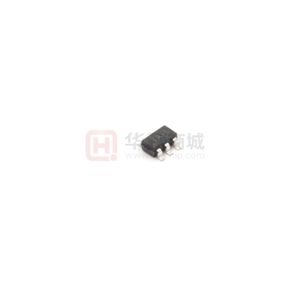
TL431AIDBVR
Programmable voltage reference
Features
SOT23-5
■
Adjustable output voltage: 2.5 to 36 V
NC
1
■
Sink current capability: 1 to 100 mA
NC
2
■
Typical output impedance: 0.22 Ω
Cathode
3
■
1% and 2% voltage precision
■
Automotive temp. range - 40 °C to +125 °C
SOT23-5
5 Anode
4 Ref
SOT23-5 pin connections (top view)
Applications
Power supply
■
Industrial
■
Automotive
Cathode
Ref
Vref
Anode
co
nd
TL431AIDBVR block diagram
CR
O
Se
mi
The TL431AIDBVR are programmable shunt
voltage references with guaranteed temperature
stability over the entire operating temperature
range. The device temperature range is extended
for the automotive version from -40 °C up to
+125 °C. The output voltage can be set to any
value between 2.5 and 36 V with two external
resistors. The TL431AIDBVR operate with a
wide current range from 1 to 100 mA with a typical
dynamic impedance of 0.22 Ω.
uc
Description
to
r
■
Absolute maximum ratings and operating conditions
Absolute maximum ratings
JS
MI
Symbol
VKA
Parameter
Cathode to anode voltage
Value
Unit
37
V
Ik
Continuous cathode current range
-100 to +150
mA
Iref
Reference input current range
-0.05 to +10
mA
Rthja
SOT23-5
157
°C/W
Rthjc
SOT23-5
67
°C/W
Tstg
Storage temperature range
-65 to +150
°C
Junction temperature
150
°C
TL431AIDBVR: HBM (human body model)
3000
V
TJ
ESD
www.jsmsemi.com
第1/6页
�TL431AIDBVR
Programmable voltage reference
Operating conditions
Symbol
Parameter
Value
Unit
Cathode to anode voltage
Vref to 36
V
Ik
Cathode current
1 to 100
mA
Toper
TL431AIDBVR
-40 to +125
°C
VKA
25°C unless otherwise specified)
Min.
Parameter
Reference input voltage
VKA = Vref, Ik = 10 mA
Tmin ≤ Tamb ≤ Tmax
ΔVref
Reference input voltage deviation over temperature
range (1)
VKA = Vref, Ik = 10 mA, Tmin≤ Tamb ≤ Tmax
ΔIref
7
mV
-2.7
-2
Se
Reference input current
Ik = 10 mA, R1 = 10 kΩ, R2 = ∞
Tmin ≤ Tamb ≤ Tmax
mi
Ratio of change in reference input voltage to change
in cathode to anode voltage
Ik = 10 mA, ΔVKA = 10 V to Vref
Ik = 10 mA, ΔVKA = 36 V to 10 V
Reference input current deviation over temperature
range
Ik = 10 mA, R1 = 10 kΩ, R2 = ∞, Tmin ≤ Tamb ≤
Tmax
Minimum cathode current for regulation
VKA = Vref
Off-state cathode current
Tmin ≤ Tamb ≤ Tmax
JS
MI
Imin
Ioff
⏐ZKA⏐
Unit
V
CR
O
Iref
Max.
2.47 2.495 2.52
2.44
2.55
co
Vref
ΔVref
-----------ΔVka
Typ.
uc
Symbol
nd
Tamb =
to
r
Electrical characteristics
Dynamic impedance (2)
VKA = Vref, Δ Ik = 1 to 100 mA, F ≤ 1 kHz
30
-1.4
-1
mV/V
1.8
4
6.5
µA
0.8
1.2
µA
0.5
0.6
mA
2.6
1000
3000
nA
0.22
0.5
Ω
ΔV KA
The dynamic impedance is defined as |ZKA| = ---------------
ΔI k
www.jsmsemi.com
第2/6页
�TL431AIDBVR
Programmable voltage reference
Reference input voltage deviation over temperature range
ΔVref is defined as the difference between the maximum and minimum values obtained over
the full temperature range.
ΔVref = Vref max - Vref min
Test circuit for VKA = Vref
uc
to
r
Reference input voltage deviation over temperature range
Test circuit for programming mode
Input
nd
R
Output
R1
IK=10mA
mi
VKA
co
Input
CR
O
Se
VREF
Test circuit for Ioff
R
R2
Output
IK
IREF
VKA
VREF
VKA = VREF ( 1 + R1
------- ) + R1 x IREF
R2
Test circuit for phase margin and voltage gain
10μF
IOFF
10μF
Output
www.jsmsemi.com
8.25kΩ
Input
IK=10mA
15kΩ
JS
MI
VKA=36V
VREF
第3/6页
�TL431AIDBVR
Programmable voltage reference
Test circuit for response time
Reference voltage vs. temperature
Output
IK=1mA
1 mA
0 mA
Cathode voltage VKA (V)
2.54
VKA = VREF
IK = 10 mA
2.52
2.50
2.48
2.44
-40
-20
0
to
r
2.46
20
40
60
80
100
120
uc
Temperature (°C)
Zoom on reference voltage vs. cathode current
CR
O
Se
mi
co
nd
Reference voltage vs. cathode current
Reference current vs. temperature
0.4
Off-state current IOFF (μA)
Reference current IREF (μA)
JS
MI
2.0
Off-state cathode current vs.
temperature
IK=10 mA
R1=10kΩ
R2= + ∝
1.5
1.0
0.5
0.0
-40
VKA = 36 V
VREF = 0 V
0.3
0.2
0.1
-20
0
20
40
60
80
100
120
0.0
-40
-20
0
20
40
60
80
100
120
Temperature (°C)
Temperature °C
www.jsmsemi.com
第4/6页
�TL431AIDBVR
Programmable voltage reference
Ratio of change in Vref to change in VKA vs.
temperature
Static impedance RKA vs. temperature
0.20
Static impedance RKA (Ω)
ΔVREF / ΔVKA (mV / V)
0.0
IK = 10 mA
-0.5
-1.0
VKA=VREF
0.18
0.16
0.14
0.12
-2.0
-40
-20
0
20
40
60
80
100
120
0.10
-40
-20
0
40
60
80
100
120
uc
Gain and phase vs. frequency
nd
Minimum operating current vs. temperature
co
0.6
mi
0.4
VKA = VREF
0.2
-20
0
20
40
Se
Minimum cathode current IMIN (mA)
20
Temperature (°C)
Temperature (°C)
0.0
-40
to
r
-1.5
60
80
100
120
CR
O
Temperature (°C)
Pulse response for Ik = 1 mA
JS
MI
Stability behavior with capacitive loads
www.jsmsemi.com
第5/6页
�TL431AIDBVR
Programmable voltage reference
SOT23-5 package information
mi
SOT23-5 package mechanical data
7049676_I
Dimensions
Millimeters
Se
Ref.
Min.
A
co
nd
uc
to
r
SOT23-5 package mechanical drawing
Typ.
0.90
Max.
Min.
1.45
0.035
Typ.
Max.
0.057
0.15
CR
O
A1
Inches
0.006
0.90
1.30
0.035
0.051
b
0.35
0.50
0.014
0.020
c
0.09
0.20
0.004
0.008
D
2.80
3.05
0.110
0.120
E
1.50
1.75
0.059
0.069
JS
MI
A2
e
0.95
0.037
H
2.60
3.00
0.102
0.118
L
0.10
0.60
0.004
0.024
θ
0 degrees
10 degrees
www.jsmsemi.com
第6/6页
�
很抱歉,暂时无法提供与“TL431AIDBVR”相匹配的价格&库存,您可以联系我们找货
免费人工找货