BAV70
Dual Switching Diode Common Cathode
Features
AEC−Q101 Qualified and PPAP Capable
S Prefix for Automotive and Other Applications Requiring Unique
Site and Control Change Requirements
These Devices are Pb−Free, Halogen Free/BFR Free and are RoHS
to
r
Compliant
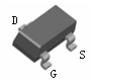
SOT−23
MAXIMUM RATINGS (EACH DIODE)
Unit
Reverse Voltage
VR
70
V
Forward Current
IF
200
mA
IFM(surge)
500
mA
Symbol
Max
Unit
PD
225
mW
Peak Forward Surge Current
THERMAL CHARACTERISTICS
1.8
RqJA
Total Device Dissipation
Alumina Substrate,
(Note 2) TA = 25C
Derate above 25C
PD
CR
O
RqJA
Junction and Storage Temperature
TJ, Tstg
mW/C
556
C/W
300
mW
2.4
mW/C
417
C/W
−55 to
+150
C
Se
Thermal Resistance,
Junction−to−Ambient
Thermal Resistance,
Junction−to−Ambient
2
ANODE
MARKING DIAGRAM
co
Total Device Dissipation FR− 5 Board
(Note 1)
TA = 25C
Derate above 25C
3
CATHODE
mi
Characteristic
ANODE
1
uc
Value
nd
Symbol
Rating
JS
MI
Stresses exceeding Maximum Ratings may damage the device. Maximum
Ratings are stress ratings only. Functional operation above the Recommended
Operating Conditions is not implied. Extended exposure to stresses above the
Recommended Operating Conditions may affect device reliability.
1. FR−5 = 1.0 � 0.75 � 0.062 in.
2. Alumina = 0.4 � 0.3 � 0.024 in. 99.5% alumina.
www.jsmsemi.com
3
A4
2
1
A4= Device Code
ORDERING INFORMATION
Device
Package
Shipping†
BAV70
SOT −23
(Pb−Free)
3000 / Tape & Reel
†For information on tape and reel specifications,
including part orientation and tape sizes, please
refer to our Tape and Reel Packaging Specifications
Brochure, BRD8011/D.
第1页,共3页
�BAV70
Dual Switching Diode Common Cathode
ELECTRICAL CHARACTERISTICS (TA = 25C unless otherwise noted) (Each Diode)
Symbol
Characteristic
V(BR)
IR
Diode Capacitance
(VR = 0 V, f = 1.0 MHz)
CD
Forward Voltage
(IF = 1.0 mA)
(IF = 10 mA)
(IF = 50 mA)
(IF = 150 mA)
VF
70
−
−
−
−
60
2.5
100
−
1.5
−
−
−
−
715
855
1000
1250
−
6.0
uc
Reverse Voltage Leakage Current (Note 3)
(VR = 25 V, TJ = 150C)
(VR = 70 V)
(VR = 70 V, TJ = 150C)
Max
trr
V
mA
pF
mV
ns
nd
Reverse Recovery Time
RL = 100 W
(IF = IR = 10 mA, IR(REC) = 1.0 mA) (Figure 1)
Unit
to
r
Reverse Breakdown Voltage
(I(BR) = 100 mA)
Min
mi
co
3. For each individual diode while second diode is unbiased.
+10 V
Se
820 W
2.0 k
100 mH
IF
tp
tr
0.1 mF
t
IF
trr
10%
t
CR
O
0.1 mF
90%
D.U.T.
50 W INPUT
SAMPLING
OSCILLOSCOPE
JS
MI
50 W OUTPUT
PULSE
GENERATOR
IR
VR
INPUT SIGNAL
iR(REC) = 1.0 mA
OUTPUT PULSE
(IF = IR = 10 mA; MEASURED
at iR(REC) = 1.0 mA)
Notes: 1. A 2.0 kW variable resistor adjusted for a Forward Current (IF) of 10 mA.
Notes: 2. Input pulse is adjusted so IR(peak) is equal to 10 mA.
Notes: 3. tp » trr
Figure 1. Recovery Time Equivalent Test Circuit
www.jsmsemi.com
第2页,共3页
�BAV70
Dual Switching Diode Common Cathode
SOT−23
NOTES:
1. DIMENSIONING AND TOLERANCING PER ANSI Y14.5M,
1982.
2. CONTROLLING DIMENSION: INCH.
3. MAXIMUM LEAD THICKNESS INCLUDES LEAD FINISH
THICKNESS. MINIMUM LEAD THICKNESS IS THE MINIMUM
THICKNESS OF BASE MATERIAL.
4. DIMENSIONS D AND E DO NOT INCLUDE MOLD FLASH,
PROTRUSIONS, OR GATE BURRS.
HE
E
c
1
DIM
A
A1
b
c
D
E
e
L
L1
HE
q
2
e
b
0.25
q
A
L
A1
MILLIMETERS
NOM
MAX
1.00
1.11
0.06
0.10
0.44
0.50
0.13
0.18
2.90
3.04
1.30
1.40
1.90
2.04
0.20
0.30
0.54
0.69
2.40
2.64
−−−
10
MIN
0.035
0.001
0.015
0.003
0.110
0.047
0.070
0.004
0.014
0.083
0
INCHES
NOM
0.040
0.002
0.018
0.005
0.114
0.051
0.075
0.008
0.021
0.094
−−−
MAX
0.044
0.004
0.020
0.007
0.120
0.055
0.081
0.012
0.029
0.104
10
nd
L1
MIN
0.89
0.01
0.37
0.09
2.80
1.20
1.78
0.10
0.35
2.10
0
to
r
SEE VIEW C
3
uc
D
PIN 1. ANODE
2. ANODE
3. CATHODE
co
VIEW C
0.95
0.037
Se
0.95
0.037
mi
SOLDERING FOOTPRINT
2.0
0.079
SCALE 10:1
0.8
0.031
mm Ǔ
ǒinches
JS
MI
CR
O
0.9
0.035
www.jsmsemi.com
第3页,共3页
�
很抱歉,暂时无法提供与“BAV70”相匹配的价格&库存,您可以联系我们找货
免费人工找货- 国内价格
- 50+0.08909
- 200+0.08319
- 600+0.07729
- 2000+0.07139
- 5000+0.06549
- 10000+0.06136