SS52BF THRU SS520BF
Surface Mount Schottky Barrier Rectifier
Reverse Voltage - 20 to 200V Forward Current - 5.0A
PINNING
PIN
FEATURES
• Metal silicon junction, majority carrier conduction
• For surface mounted applications
• Low power loss, high efficiency
• High forward surge current capability
• For use in low voltage, high frequency inverters,
free wheeling, and polarity protection applications
DESCRIPTION
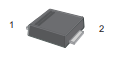
1
Cathode
2
Anode
1
2
Top View
Marking Code: S52B — S520B
Simplified outline SMBF and symbol
MECHANICAL DATA
• Case: SMBF
• Terminals: Solderable per MIL-STD-750, Method 2026
• A pprox. Weight: 57 mg / 0.002oz
Absolute Maximum Ratings and Electrical characteristics
Ratings at 25 °C ambient temperature unless otherwise specified.Single phase, half wave, 60Hz resistive or inductive load,
for capacitive load, derate by 20 %
Symbols
Parameter
SS52BF
SS54BF
SS56BF
SS58BF
SS510BF SS512BF SS515BF SS520BF
Units
Maximum Repetitive Peak Reverse Voltage
V RRM
20
40
60
80
100
120
150
200
V
Maximum RMS voltage
V RMS
14
28
42
56
70
84
105
140
V
Maximum DC Blocking Voltage
V DC
20
40
60
80
100
120
150
200
V
Maximum Average Forward Rectified Current
I F(AV)
5.0
A
Peak Forward Surge Current,8.3ms
Single Half Sine-wave Superimposed
on Rated Load (JEDEC method)
I FSM
150
A
Max Instantaneous Forward Voltage at 5 A
Maximum DC Reverse Current
T a = 25°C
at Rated DC Reverse Voltage
T a =100°C
Typical Junction Capacitance 1)
Typical Thermal Resistance
2)
0.45
0.55
V
mA
500
800
pF
RθJA
40
°C/W
Tj
-55 ~ +125
°C
T stg
-55 ~ +150
°C
at 1MHz and applied reverse voltage of 4 V D.C.
P.C.B. mounted with 0.5 X 0.5" (12.7 X 12.7 mm) copper pad areas.
REV.08
0.85
1.0
50
1) Measured
2)
0.70
IR
Cj
Operating Junction Temperature Range
Storage Temperature Range
VF
1 of 3
�SS52BF THRU SS520BF
Fig.2 Typical Reverse Characteristics
Instaneous Reverse Current ( μA)
Fig.1 Forward Current Derating Curve
Average Forward Current (A)
6.0
100LFM
5.0
4.0
3.0
2.0
Single phase half wave resistive
or inductive P.C.B mounted on
0.5×0.5"(12.7×12.7mm ) pad areas
1.0
0.0
25
50
75
100
125
150
10 4
T J =100°C
10 3
10 1
T J =25°C
10 0
0
Lead Temperature (°C)
60
80
100
Fig.4 Typical Junction Capacitance
T J =25°C
Junction Capacitance ( pF)
20
10
1
SS52BF
SS54BF
SS56BF/SS58BF
SS510BF/SS520BF
0.1
0
0.5
1.0
1.5
100
SS52BF/SS54BF
SS54F/SS520F
SS56BF-SS520BF
20
10
0.1
1
10
100
Reverse Voltage (V)
Fig.5 Maximum Non-Repetitive Peak
Forward Surage Current
Fig.6- Typical Transient Thermal Impedance
150
125
100
75
50
8.3 ms Single Half Sine Wave
(JEDEC Method)
00
1
500
Instaneous Forward Voltage (V)
175
25
1000
2.0
Transient Thermal Impedance( °C /W)
Instaneous Forward Current (A)
Peak Forward Surage Current (A)
40
20
Percent of Rated Peak Reverse Voltage(%)
Fig.3 Typical Forward Characteristic
10
100
Number of Cycles at 60Hz
REV.08
T J =75°C
10 2
100
10
1
0.01
0.1
1
10
t, Pulse Duration(sec)
2 of 3
100
�SS52BF THRU SS520BF
PACKAGE OUTLINE
Plastic surface mounted package; 2 leads
SMBF
∠ALL ROUND
C
A
∠ALL ROUND
D
E
A
V M
g
Top View
mil
Bottom View
g
A
C
D
E
HE
e
max
1.3
0.26
4.4
3.7
5.5
2.2
min
1.1
0.18
4.2
3.5
5.1
1.9
max
51
10
173
146
216
86
min
43
7
165
138
200
75
UNIT
mm
g
pad
e
E
A
pad
HE
1.0
9°
40
Marking
The recommended mounting pad size
Type number
3.0(118)
1.8(71)
2.54(100)
1.8(71)
Unit:mm(mil)
REV.08
∠
3 of 3
Marking code
SS52BF
S52B
SS54BF
S54B
SS56BF
S56B
SS58BF
S58B
SS510BF
S510B
SS512BF
S512B
SS515BF
S515B
SS520BF
S520B
�
很抱歉,暂时无法提供与“SS512BF”相匹配的价格&库存,您可以联系我们找货
免费人工找货