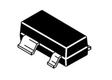
SR15W
LOW CAPACITANCE TVS DIODE ARRAY
Features
●
●
●
●
●
●
Ultra low leakage: nA level
Operating voltage: 15V
Low clamping voltage
Complies with following standards:
– IEC 61000-4-2 (ESD) immunity test
Air discharge: ±30kV
Contact discharge: ±30kV
– IEC61000-4-4 (EFT) 40A (5/50ns)
– IEC61000-4-5 (Lightning) 11A (8/20μs)
RoHS Compliant
Dimensions SOT-143
AEC-Q101 qualified
Pin Configuration
Applications
●
USB Power & Data Line Protection
●
Ethernet 10BaseT
●
I2C Bus Protection
●
Video Line Protection
●
T1/E1 secondary IC Side Protection
●
Microcontroller Input Protection
●
ISDN S/T Interface
●
WAN/LAN Equipment
Mechanical Characteristics
●
SOT-143 Package
●
Molding Compound Flammability Rating : UL 94V-O
●
Weight 10 Millgrams (Approximate)
●
Quantity Per Reel : 3,000pcs
●
Reel Size : 7 inch
●
Lead Finish : Lead Free
Absolute Maximum Ratings(Tamb=25°C unless otherwise specified)
Parameter
Peak Pulse Current (8/20μs)
ESD per IEC 61000−4−2 (Air)
Symbol
Ppp
Value
Unit
350
W
±30
VESD
Kv
±30
ESD per IEC 61000−4−2 (Contact)
Operating Temperature Range
TJ
-55 to +125
℃
Storage Temperature Range
TSTJ
-55 to +150
℃
Rev 2.0 : 12.01.2019
1/7
www.leiditech.com
�SR15W
Electrical Characteristics(TA=25°C unless otherwise specified)
Vc
Part Number
SR15W
Device
Marking
VRWM
(V)
VBR
(V)
LKD
15
16.5
Rev 2.0 : 12.01.2019
IT
(mA)
1
VC
@1A
20
2/7
(Max)
32
(@A)
11
IR
μA
(Max)
1
C
(Pf)
(Typ.)
5
www.leiditech.com
�SR15W
TYPIC CHARACTERISTICS
Figure 1.
8 x 20μs Waveform
Figure 2.
Power Derating Curve
Figure 3. Clamping Voltage vs. Peak Pulse Current (tp=8/20μs)
Rev 2.0 : 12.01.2019
3/7
www.leiditech.com
�SR15W
TYPIC CHARACTERISTICS
Figure 4. Typic Breakdown Voltage vs. Temperature
Figure 5. Typic Reverse Current vs. Temperature
Rev 2.0 : 12.01.2019
4/7
www.leiditech.com
�SR15W
TYPIC CHARACTERISTICS
Figure 6. Typic Capacitance vs. Reverse Voltage
Rev 2.0 : 12.01.2019
5/7
www.leiditech.com
�SR15W
1. Data lines and power supply protection using Vcc as referance
To protect data lines and the power line, connect
Pin 4 directly to the positive supply rail (Vcc).
In this configuration the data lines are referanced
to the supply voltage. The internal TVS diode prevents
over-voltage on the supply rail.
The path length is kept as short as possible to
minimize parasitic inductance.'
2. Data lines protection with bias and power supply isolation resistor
The SR15W serise can be isolated from the
power supply by adding a series resistor between pin 4
and Vcc+. A value or 10kΩ is recommended. The internal
TVS and steering diodes remain biased, providing the
advantage of lower capacitance.
The path length is kept as short as possible to
minimize parasitic inductance.
3. Data lines protection using internal TVS diodes as referance
In applications where no positive supply referance is
available, or complete supply isolation is desired,
the internal TVS may be used as the referance.
In the case, pin 4 is not connected. The steering diodes
will begin to conduct the voltage on the protected line
exceeds the working voltage of the TVS
(plus one diode drop).
Rev 2.0 : 12.01.2019
1/7
www.leiditech.com
�SR15W
SOT-143 Package Outline & Dimensions
Shanghai Leiditech Electronic Co.,Ltd
Email: sale1@leiditech.com
Tel : +86- 021 50828806
Fax : +86- 021 50477059
Rev 2.0 : 12.01.2019
7/7
www.leiditech.com
�
很抱歉,暂时无法提供与“SR15W”相匹配的价格&库存,您可以联系我们找货
免费人工找货