物料型号:FP1005R系列,包括不同版本(R1, R2, R3, R4)和不同的电感值。
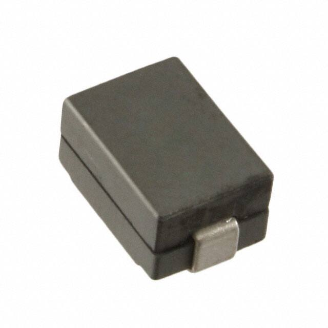
器件简介:这些电感器具有高电流承载能力、低芯损、磁屏蔽和高达2MHz的频率范围。它们采用10.2mm x 7.0mm的表面贴装封装,高度为4.95mm。
引脚分配:文档中未明确提供引脚分配信息,但提供了推荐的焊盘布局和原理图。
参数特性:电感范围从85nH到220nH,电流范围从33A到90A。文档详细列出了不同版本的电感器的开路电感(OCL)、满载电感(FLL)、饱和电流(Isat1和Isat2)、直流电阻(DCR)、K因子等参数。
功能详解:电感器适用于多相和Vcore调节器、电压调节模块(VRMs)、服务器和桌面CPU、GPU、ASIC、高功率密度、数据网络和存储系统、图形卡、电池电源系统、便携式电子设备和点对点模块。
应用信息:适用于需要高功率密度和高电流的应用,如CPU、GPU、ASIC、数据网络和存储系统等。
封装信息:提供了详细的尺寸信息、推荐的焊盘布局、原理图和部件标记信息。还提供了关于焊接回流曲线的指导。
环境数据:包括存储和工作温度范围(-40°C至+125°C),以及符合J-STD-020D标准的焊接回流温度。