物料型号:SMDJ5.0(C)A 至 SMDJ170(C)A
器件简介:瞬态电压抑制器,适用于表面贴装应用,优化板空间,低轮廓封装,内置缓释装置,玻璃钝化结,低电感,优秀的钳位能力,3000W峰值脉冲功率能力。
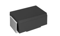
引脚分配:文档中没有明确指出具体的引脚分配,但提到了极性符号标记在封装上。
参数特性:包括最大脉冲功率耗散、最大瞬态正向电压、稳态功率耗散、峰值正向浪涌电流、工作结温和存储温度范围等。
功能详解:器件具有快速响应时间,典型IR小于1μA在10V以上,高温焊接能力,塑料封装具有UL94V-0可燃性等级。
应用信息:适用于I/O接口、交流/直流电源供应、低频信号传输线(如RS232、RS485等)。
封装信息:JEDEC SMC模塑塑料封装,尺寸以英寸和毫米为单位提供,重量为0.003盎司或0.095克,标准包装为12mm胶带。