0
登录后你可以
  • 下载海量资料
  • 学习在线课程
  • 观看技术视频
  • 写文章/发帖/加入社区
会员中心
创作中心
发布
  • 发文章

  • 发资料

  • 发帖

  • 提问

  • 发视频

创作活动
AIP555

AIP555

  • 厂商:

    I-CORE(中微爱芯)

  • 封装:

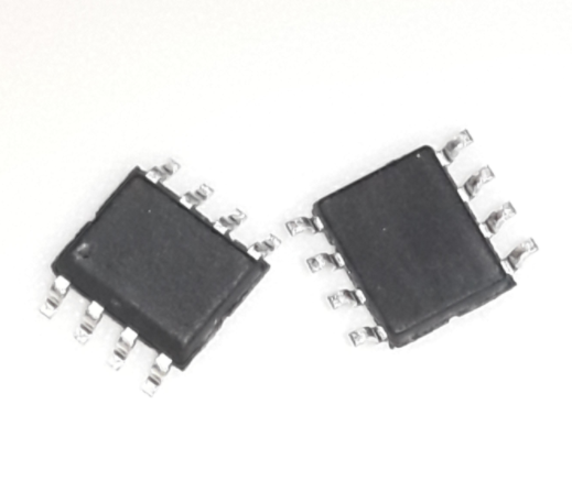
    SOP8_150MIL

  • 描述:

    可编程计时器和振荡器 SOP-8 2~18V 1MHz

  • 详情介绍
  • 数据手册
  • 价格&库存
AIP555 数据手册
Wuxi I-CORE Electronics Co., Ltd. rev:B2 Number: AiP555-AX-BJ-452 e Tab: 835-12 or AiP555 General Purpose Timers Specification i-c Product Specification Revision History : Version Data Description 2017-11-A1 2017-11 New-made Address:Building B4,NO.777,Jianzhu Road,Binhu Distrct,Wuxi City,Jiangsu Province http://www.i-core. cn P.C:214072 1/ 11 VER:2017-11-A1 Tab: 835-12 Wuxi I-CORE Electronics Co., Ltd. rev:B2 Number: AiP555-AX-BJ-452 1、General Description e The AiP555 is a CMOS RC timer providing significantly improved performance over the standard SE/NE 555 timer, while at the same time being a direct replacement for those devices in most applications. Improved parameters include low supply current, wide operating supply voltage range, low Threshold, Trigger and Reset currents, no crowbarring of the supply current during output transitions, higher frequency performance and no requirement to decouple Control Voltage for stable operation. Specifically, the AiP555 is a stable controller capable of producing accurate time delays or frequencies. In the one shot mode, the pulse width of each circuit is precisely controlled by one external resistor and capacitor. For astable operation as an oscillator, the free running frequency and the duty cycle are both accurately controlled by two external resistors and one capacitor. Unlike the regular bipolar 555 device, the Control Voltage terminal need not be decoupled with a capacitor. The circuits are triggered and reset on falling (negative) waveforms, and the output inverter can source or sink currents large enough to drive TTL loads, or provide minimal offsets to drive CMOS loads. 2、Block Diagram And Pin Description i-c or 2.1、Block Diagram NOTE: UNUSED INPUTS SHOULD BE CONNECTED TO APPROPRIATE VOLTAGE FROM TRUTH TABLE 2.2、Pin Configurations GND 1 /TRIGGER 2 OUTPUT 3 /RESET 4 AiP555 8 VDD 7 DISCHARGE 6 THRESHOLD 5 CONTROL VOLTAGE Address:Building B4,NO.777,Jianzhu Road,Binhu Distrct,Wuxi City,Jiangsu Province http://www.i-core. cn P.C:214072 2/ 11 VER:2017-11-A1 Tab: 835-12 Wuxi I-CORE Electronics Co., Ltd. rev:B2 Number: AiP555-AX-BJ-452 2.3、Pin Description Pin No. 1 Pin Name GND Description Ground 2 3 4 /TRIGGER OUTPUT /RESET Trigger Voltage Input Voltage Signal Output Reset Voltage Input 5 6 CONTROL VOLTAGE THRESHOLD 7 DISCHARGE 8 VDD Control Voltage Input Threshold Voltage Input Discharge Switch 3、Electrical Parameter 3.1、 Absolute Maximum Ratings e Power (Tamb=25℃, All voltage referenced to Vss, unless otherwise specified) Symbol VDD Conditions Value +18 Unit V or Characteristic Power Supply Voltage Trigger, Control Input Voltage VIN Output Current -0.3~VDD+0.3 V IOUT 100 mA Operating Temperature Topr -25~85 ℃ Storage Temperature Tstg -55~125 ℃ Power Dissipation Soldering Temperature PD TL 500 245 mW ℃ Voltage, Threshold, Reset i-c 10s 3.2、Electrical Characteristics (Tamb=25℃, unless otherwise specified) Parameter Symbol Conditions Static Supply Current IDD Min. Typ. Max. Unit Monostable Timing Accuracy VDD=5V VDD=15V 40 60 200 300 μA μA RA=10k, C=0.1μF, VDD=5V 2 % Drift with Supply VDD=5V to 15V 0.5 %/V Astable Timing Accuracy RA=RB=10k, C=0.1μF, VDD=5V 2 % Drift with Supply VDD=5V to 15V 0.5 %/V Threshold Voltage VTH VDD=15V 62 67 71 %VDD Trigger Voltage VTRIG VDD=15V 28 32 36 %VDD Address:Building B4,NO.777,Jianzhu Road,Binhu Distrct,Wuxi City,Jiangsu Province http://www.i-core. cn P.C:214072 3/ 11 VER:2017-11-A1 Tab: 835-12 Wuxi I-CORE Electronics Co., Ltd. rev:B2 Number: AiP555-AX-BJ-452 Threshold Current ITH VDD=15V 10 nA Trigger Current ITRIG VDD=15V 10 nA Control Voltage VCV VDD=15V 62 71 %VDD Reset Voltage VRST VDD=2V to 15V 0.4 1.0 V Reset Current IRST VDD=15V 10 nA Discharge Leakage IDIS VDD=15V 10 nA Output Voltage VOH VDD=15V,ISINK=20mA 0.4 1.0 V VDD=5V,ISINK=3.2mA 0.2 0.4 V e VOL 67 VDD=15V,ISOURSE=0.8mA 14.3 14.6 V VDD=5V,ISOURSE=0.8mA 4.0 4.3 V Discharge Output Voltage VDIS Supply Voltage VDD Functional Operation Output Rise Time tR RL=10M, CL=10pF, VDD=5V 75 ns Output Fall Time tF RL=10M, CL=10pF, VDD=5V 75 ns Oscillator Frequency fMAX 1 MHz 0.2 0.4 V 18.0 V or VDD=5V, ISINK=15mA VDD=5 i-c V,RA=470Ω, RB=270Ω, 2.0 3.3、Truth Table Threshold Voltage Trigger Voltage Reset Output Discharge Switch Don’t Care Don’t Care Low Low On >2/3(V+) >1/3(V+) High Low On 1/3(V+) High Stable Stable Don’t Care
AIP555
物料型号:AiP555-AX-BJ-452

器件简介:AiP555是一款CMOS RC定时器,提供了比标准SE/NE 555定时器更优越的性能,同时在大多数应用中可以直接替代这些设备。

它具备低供电电流、宽工作电压范围、低阈值、低触发和复位电流等特点。


引脚分配: - GND(1):地 - /TRIGGER(2):触发电压输入 - OUTPUT(3):电压信号输出 - /RESET(4):复位电压输入 - CONTROL VOLTAGE(5):控制电压输入 - THRESHOLD(6):阈值电压输入 - DISCHARGE(7):放电开关 - VDD(8):电源

参数特性: - 电源电压:+18V - 输入电压:-0.3~Vpp+0.3V - 输出电流:100mA - 工作温度:-25~85°C - 存储温度:-55~125°C - 功耗:500mW - 焊接温度:245°C (10s)

功能详解: - 作为标准555定时器的直接替代品,AiP555在输出驱动时不会产生较大的瞬态电流,因此通常不需要对电源进行解耦。

- 在大多数情况下,由于AiP555内部CMOS比较器的输入阻抗非常高,控制电压端不需要解耦电容。

- 输出驱动能力足以驱动大多数逻辑系列,包括CMOS和TTL。

- 在单稳态模式下,定时器作为单次触发器工作,通过外部电阻和电容器控制脉冲宽度。

- 在稳态模式下,定时器作为振荡器工作,通过两个外部电阻和一个电容器控制自由振荡频率和占空比。


应用信息:AiP555适用于需要精确时间延迟或频率控制的应用,如定时器、脉冲宽度调制器、振荡器等。


封装信息:提供了DIP8和SOP8两种封装形式的尺寸信息。
AIP555 价格&库存

很抱歉,暂时无法提供与“AIP555”相匹配的价格&库存,您可以联系我们找货

免费人工找货
AiP555
  •  国内价格
  • 5+1.41372
  • 50+1.08713
  • 200+0.94716
  • 500+0.77253
  • 2500+0.69477
  • 5000+0.64800

库存:37