WS4622C
WS4622C
2A, 38 mΩ, 250nA Quiescent current and 90nA
Http://www.sh-willsemi.com
Standby current Load Switch
Descriptions
The WS4622C is a single channel load switch with
ultra-low on resistance MOSFET. It is designed for load
switching applications with ultra-low quiescent current
(250nA) and ultra-low standby current (90nA).The
device is controlled by external logic pin, allowing
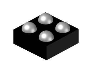
CSP-4L
optimization of battery life, and portable device
autonomy.
The WS4622C contains a P-channel MOSFET that
can operate over an input voltage range of 1.2V to
5.5V and can support a maximum continuous current
of 2A. Output discharge path is designed to reduce
voltage on the output rail quickly.
The WS4622C are available in a small 1 x 1mm
Pin Configuration (Top View)
CSP-4L Package. Standard products are Pb-free and
Halogen-free.
Features
Input Voltage Range
:1.2V~5.5V
Main switch Ron
: 38mΩ @ 4.2V
Maximum Output current
: 2A.
Quiescent current
: 250nA @ Typ
Standby current
: 90nA @ Typ
Recommend capacitor
: 1μF
Active High EN Pin
Y : Year code
Output Auto-discharge
W : Week code
CSP-4L 1 x 1 mm
CSP-4L
22 : Device code
Marking
Applications
MP3/MP4 Players
Cellphones, radiophone, digital cameras
Bluetooth, wireless handsets
Others portable electronics device
Will Semiconductor Ltd.
Order information
Device
WS4622C-4/TR
1
Marking
Package
Shipping
22YW
CSP-4L
3000/Reel&Tape
Apr, 2019 – Rev 1.0
�WS4622C
Typical Application
Pin Description
PIN
Symbol
Description
A1
OUT
A2
IN
Input pin
B1
GND
Ground
B2
EN
Output pin
Enable (Active high)
Block Diagram
Will Semiconductor Ltd.
2
Apr, 2019 – Rev 1.0
�WS4622C
Absolute Maximum Ratings
Parameter
Value
VIN Range
-0.3~6.5
V
VEN Range
-0.3~6.5
V
VOUT Range
-0.3~6.5
V
Storage Temperature Range
-40 ~ 150
o
Junction Temperature Range
-40 ~ 125
oC
Lead Temperature
260
o
Moisture Sensitivity
Level-1
ESD Ratings
Unit
C
C
HBM
8000
V
MM
400
V
Recommend Operating Ratings
Parameter
Value
Operating Power voltage
1.2~5.5
V
Enable Voltage
0~5.5
V
Maximum DC current
2
A
Operating ambient temperature
-40~85
o
Operating Junction temperature
-40~125
o
Decoupling input capacitor
1
uF
1
uF
Power Dissipation Rating(25 C,WLCSP package)
0.5
W
Power Dissipation Rating(85 C,WLCSP package)
0.2
Thermal Resistance, RθJA (CSP-4L)
100
Decoupling output capacitor
o
o
Will Semiconductor Ltd.
3
Unit
C
C
W
C/W
o
Apr, 2019 – Rev 1.0
�WS4622C
Electronics Characteristics
(Ta=25oC, VIN=5V, CIN=COUT=1μF, unless otherwise noted)
Parameter
Input Voltage
Static drain-source
on-state resistance
Symbol
Condition
VIN
RDSON
Min.
Typ.
1.2
Max.
Unit
5.5
V
VIN =5.5,IOUT =200mA
34
42
VIN =4.2,IOUT =200mA
38
47
VIN =3.3,IOUT =200mA
42
52
VIN =1.8,IOUT =200mA
62
88
VIN =1.2,IOUT =200mA
104
250
EN=Low,VIN=3.3V
65
120
mΩ
Output discharge path
RDIS
EN logic high voltage
VENH
EN logic low voltage
VENL
EN pull down resistor
RPD
Standby current
ISTD
EN=Low, No load
90
500
nA
Quiescent current
IQ
EN=High,No load
250
500
nA
Enable time
TEN
VIN =3.6,RL=25ohm
40
μs
Output rise time
TR
VIN =3.6,RL=25ohm
30
μs
ON time(TEN+TR)
TON
VIN =3.6,RL=25ohm
70
μs
Output fall time
TF
VIN =3.6,RL=25ohm
42
μs
0.9
V
0.5
4
4
V
MΩ
Enable, rise and fall time
Will Semiconductor Ltd.
Ω
Apr, 2019 – Rev 1.0
�WS4622C
Typical characteristics (Ta=25oC, VIN=5V,IOUT=200mA, CIN=COUT=1μF, unless otherwise noted)
Will Semiconductor Ltd.
5
Apr, 2019 – Rev 1.0
�WS4622C
Will Semiconductor Ltd.
6
Apr, 2019 – Rev 1.0
�WS4622C
Turn On & Turn Off
(1)Start from VIN.
VIN=VEN=3.6V,IOUT=100mA
VIN=VEN=3.6V,IOUT=1A
(2)Start from EN
VIN=VEN=3.6V,IOUT=100mA
VIN=VEN=3.6V,IOUT=1A
(3)Shutdown from VIN
VIN=VEN=3.6V,IOUT=100mA
VIN=VEN=3.6V,IOUT=1A
(4)Shutdown from EN
VIN=VEN=3.6V,IOUT=100mA
Will Semiconductor Ltd.
VIN=VEN=3.6V,IOUT=1A
7
Apr, 2019 – Rev 1.0
�WS4622C
ACKAGE OUTLINE DIMENSIONS
CSP-4L
D
e
E
e
b
TOP VIEW
BOTTOM VIEW
0.50
Package Outline
A2
A
A1
0.50
A3
Φ0.30
SIDE VIEW
RECOMMENDED LAND PATTERN (unit:mm)
Symbol
Dimensions in Millimeters
Min.
Typ.
Max.
A
0.55
0.58
0.62
A1
0.22
0.24
0.26
A2
0.30
0.32
0.34
A3
0.03 Ref.
D
0.94
0.97
1.00
E
0.94
0.97
1.00
e
b
Will Semiconductor Ltd.
0.50BSC
0.30
0.32
8
0.34
Apr, 2019 – Rev 1.0
�WS4622C
TAPE AND REEL INFORMATION
Reel Dimensions
RD
Reel Dimensions
W
Tape Dimensions
P1
Quadrant Assignments For PIN1 Orientation In Tape
Q1
Q2
Q1
Q2
Q3
Q4
Q3
Q4
RD
Reel Dimension
W
Overall width of the carrier tape
P1
Pitch between successive cavity centers
Pin1
Pin1 Quadrant
Will Semiconductor Ltd.
User Direction of Feed
9
7inch
13inch
1 8mm
12mm
16mm
2mm
4mm
8mm
Q1
Q2
Q3
Q4
Apr, 2019 – Rev 1.0
�
