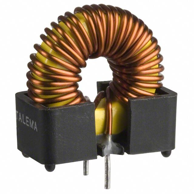
SW Series • Inductors for National's 50kHz Simple Switcher TM
Compatible with National Semiconductor's Simple SwitcherTM
Part Number's LM2574, LM2475 and LM2576
Features
•
•
•
•
•
High energy storage with minimum saturation
High stability from no load to full load
Available in both SMD and TH versions
Manufactured in ISO-9001 approved facility
Operating temperature range: -40°C to +125°C
Electrical Specifications at 25°C ambient
Rated
Current
(IDC)
LN (µH)
Typical *
LO (µH)
± 20%
N o D C L o ad
ETOP
(V-µSec)
Max.
DCR
(Ohms)
Max.
"C"
"S"
" T"
SW_-3.0-47
3.0
47
38
90
0.05
2
5
5
SWC-3.0-68
3.0
68
55
90
0.02
4
SWC-3.0-100
3.0
100
91
90
0.04
4
SW_-2.0-150
2.0
150
130
90
0.10
4
6
3
6
6
Part Number
SW_-1.4-220
1.4
220
230
90
0.38
SW_-1.4-220
1.4
220
176
90
0.14
P ackag e
5
SW_-0.9-330
0.9
330
302
90
0.74
SW_-0.9-330
0.9
330
267
90
0.18
3
5
SWC-0.64-470
0.64
470
426
90
0.16
4
SW_-0.85-680
0.85
680
657
90
1.25
SWC-3.0-150
3.0
150
136
200
0.10
5
" F"
"V"
5
2
2
5
2
2
5
2
2
4
SWC-3.0-220
3.0
220
167
200
0.07
5
SWC-3.0-330
3.0
330
292
200
0.15
5
SWC-2.0-470
2.0
470
369
200
0.17
5
SWC-1.3-680
"B"
1.3
680
562
200
0.20
5
SWC-0.95-1000
0.95
1000
762
200
0.24
5
SWB-0.62-1500
0.62
1500
1150
200
1.00
8
SWB-0.42-2200
0.42
2200
1730
200
1.80
8
Notes:
1)
Inductance will be typical for theDCI and ETOP
values listed above.
2)
No load Inductance will be measured @
20kHz, 10mVrms.
Simple SwitcherTM is a trademark of National
3)
Semiconductor Corporation.
Ordering Key
SW C - 3.0 - 47
Inductance Value in µH
Current Rating (Amps)
Mounting Style - Specify the appropriate suffix
C = Clip Mount
S = Surface Mount (S5 or S6)
T = Low Profile TH Mount
B = Base Mount
F = Flat Encapsulated
V = Vertical Encapsulated
Basic Series Designation
AMGIS, LLC * 10830 Kinghurst Dr. Houston, TX 77099
Phone: 832-775-1319 * Fax: 281-933-9067* email: sales@amgistoroids.com
Toll Free: 877-762-6447 * www.amgistoroids.com
�Mounting Styles • SW Series • Low Cost Toroidal Inductors
Type "B" - Vertical Mount
Type "V" - Vertical Mount - Size 2
AMGIS
SWV-XX-XXX
Date Code
Schematic
1.38 Max
(35.0)
0.394
(10.0)
1
0.031
(Ø 0.80)
AMGIS
2
SWB-XX-XXX
Date Code
2.00
(5.1)
Suggested Pad
Layout
1
0.591
(15.0)
0.071
(1.80)
0.80
(20.3)
0.598
(15.2)
0.709
18.0
Type "F" - Flat Mount - Size 2
0.055
(1.40)
1.10
(27.9)
1.45
(36.8)
0.043
(1.10)
0.394
(10.0)
0.598
(15.2)
0.094
(2.40)
2
2
0.512
(13.0)
0.901
(22.9)
1
AMGIS
SWF-XX-XXX
Date Code
Type SWT -Through Hole Mount
Suggested Pad
Layout
(Top Side View)
2
0.600
(15.24)
AMGIS
0.600
(15.24)
0.157±0.039
(4.0 ±1.0)
0.591
(15.0)
0.901
(22.9)
0.157±0.039
(4.0 ±1.0)
0.701
(17.8)
Suggested Pad
Layout
(Top Side View)
0.709
(18.0)
Date Code
SWT-xxx-xx
0.422
(10.71)
0.591
(15.0)
0.071
(1.80)
0.043
(1.10)
0.600
(15.24)
0.138
3.50
0.394
(10.0)
0.138±0.01
(3.5 ±0.3)
0.394
(10.0)
0.400
(10.16)
1
0.400
(10.16)
0.669
(17.0)
0.394
(10.0)
0.67
(17.0)
0.024 x 0.035
(0.60 x 0.88)
Suggested Pad
Layout
(Top Side View)
0.49
(12.5)
0.591 0.69
(15.0) (17.5)
0.059
(1.50)
0.035
(0.90)
Type SWS - Surface Mount
B
D
Type SWC - Clip Mount
D
A
Schematic
Pad Width
S6
S1 - S5
0.079
0.059
(2.00)
(1.50)
AMGIS
1
X
E
Date Code
SWS-xxx-xx
Suggested Pad
Layout
Schematic
1/2
c
1
C
2
Mounting
Style
2
Suggested Pad
Layout
0.071
E
(1.80)
E
D
0.138
(3.50)
0.047
(1.20)
C
Surface Coplanarity will be
很抱歉,暂时无法提供与“SWC-1.4-220”相匹配的价格&库存,您可以联系我们找货
免费人工找货