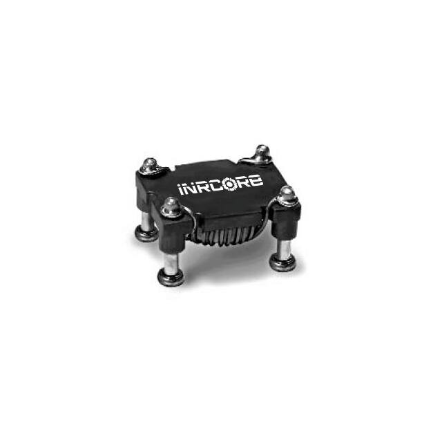
SMT POWER INDUCTORS
Toroid - Military/Aerospace POGO Series
Ruggedized
Ruggedized header with POGO pins for secure board mounting
Current Rating: up to 8.3ADC
Inductance Range: 2.0µH to 336µH
Moisture Sensitivity Level: 1
Electrical Specifications @ 25 °C — Operating Temperature - 40 °C to +130 °C
9
Inductance
@ Irated
(µH MIN)
Irated
DCR (MAX)
ET
Part
(A)
(V-µsec)
Number
(mΩ)
POGO 25
2.0
8.30
8.0
7.31
PL8600
2.4
7.20
10.9
7.81
PL8601
5.0
5.20
19.0
11.72
PL8602
7.0
4.16
16.0
14.61
PL8600
9.3
3.80
30
16.12
PL8603
8.4
3.78
21.8
15.62
PL8601
14.1
3.10
45.5
19.73
PL8604
19.8
2.60
66.5
23.45
PL8605
17.9
2.60
38.0
23.43
PL8602
29.3
2.20
101
28.50
PL8606
33.8
1.89
60
32.25
PL8603
42.6
1.80
151
34.49
PL8607
50.9
1.54
91
39.46
PL8604
61.3
1.50
222
40.85
PL8608
71.5
1.30
133
46.90
PL8605
84.2
1.20
318
46.22
PL8609
106.1
1.07
202
57.00
PL8606
154.2
0.89
302
68.99
PL8607
218.9
0.74
444
81.70
PL8608
295.0
0.64
636
92.43
PL8609
NOTES:
1. Temperature rise is 50°C in typical buck or boost circuits at 250kHz and with the reference ET
applied to the inductor.
2. Total loss in the inductor is 380mWatts for a 50°C temperature rise above ambient.
3. To estimate temperature rise in a given application, determine copper and core losses, divide
by 380 and multiply by 50.
4. For the copper loss, calculate IDC2 X RN.
5. For core loss, using frequency (f) and operating flux density (B),
calculate 6.11 x 10⁻¹⁸ x B2.7 x f2.04.
Mechanical
Inductance
@0ADC
(µH ±10%)
2.2
2.6
5.5
8.75
10.4
10.4
15.7
22.1
22.45
32.8
41.7
47.6
62.8
67.5
88.2
91.0
131.0
190.3
270.2
364.0
(V-µsec)
1 Amp DC
H1
(Orsted)
1.20
1.33
1.93
2.41
2.65
2.65
3.25
3.86
3.86
4.70
5.30
5.66
6.51
6.75
7.71
7.83
9.40
11.33
13.50
15.66
5.43
5.97
8.69
10.86
11.95
11.95
14.66
17.38
17.38
21.18
23.89
25.52
29.32
30.41
34.75
35.30
42.36
51.05
60.82
70.59
100 Gauss ET100
Connection
Parallel
Parallel
Parallel
Series
Parallel
Series
Parallel
Parallel
Series
Parallel
Series
Parallel
Series
Parallel
Series
Parallel
Series
Series
Series
Series
6. For flux density (B), calculate ET (V-µsec) for the application, divide by ET100 from the
table, and multiply by 100.
7. Limit the DC bias (H) to 46 orsteds. Calculate H by multiplying H1 from the table by IDC of
the application.
8. The maximum DCR listed is approximately 17% over the nominal DCR.
9. Optional Tape & Reel packaging can be ordered by adding a "T" suffix to the part number
(i.e. PL8600 becomes PL8600T).
Electrical Schematic
4
3
2
4
1
1
3
www.inrcore.com
M114.D (07/20)
�SMT POWER INDUCTORS
Toroid - Military/Aerospace POGO Series
Ruggedized
For More Information
Global Sales Representatives and Lo cations:
http://www.inrcore.com
iNRCORE,LLC
311 Sinclair Road Bristol,
PA 19007-6812 U.S.A
Tel: + 1.215.781.6400
Fax: +1.215.7816430
Performance warranty of products offered on this data sheet is limited to the parameters specified. Data is subject to change without notice. Other brand and product names
mentioned herein may be trademarks or registered trademarks of their respective owners. © Copyright, 2020. iNRCORE, LLC. All rights reserved.
2
www.inrcore.com
M114.D (07/20)
�
很抱歉,暂时无法提供与“PL8609T”相匹配的价格&库存,您可以联系我们找货
免费人工找货