Technical Data 10354
Effective October 2017
Supersedes April 2015
HCV1206
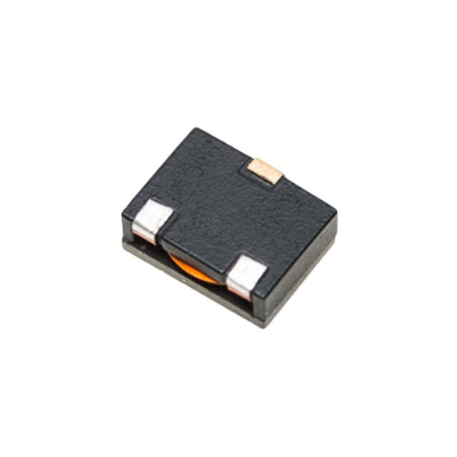
High current power inductors
Applications
•
Compatible with Picor® Cool-Power®
ZVS Buckand Buck-Boost Regulator Families
(Picor part number series PI37xx and PI35xx)
Environmental data
Product features
•
Flat-wire construction
•
Low DCR, high efficiency
•
Secure 3 terminal mounting
•
12.7 mm x 10.15 mm footprint surface mount
package in a 5.1 mm height
•
Ferrite core material
•
Storage temperature range (component):
-55 °C to +125 °C
•
Operating temperature range: -55 °C to +125 °C
(ambient plus self-temperature rise)
•
Solder reflow temperature:
J-STD-020 (latest revision) compliant
HALOGEN
Pb HF
FREE
Picor® and Cool-Power® are trademarks of Vicor Corporation.
�HCV1206
High current power inductors
Technical Data 10354
Effective October 2017
Product Specifications
Part Number4
OCL1
(μH) ±10%
Irms2
(A)
Isat3
(A)
DCR (mΩ)
@ +20 °C
±10%
HCV1206-R42-R
0.42
16
42
3.15
HCV1206-R48-R
0.48
16
37
3.15
HCV1206-R90-R
0.90
14
28
4.6
HCV1206-1R0-R
1.0
14
24.5
4.6
HCV1206-1R5-R
1.5
12
21
6.0
HCV1206-2R0-R
2.0
12
16
6.0
HCV1206-3R0-R
3.0
11
13
7.4
1. Open Circuit Inductance (OCL) Test Parameters: 100 kHz, 0.1 Vrms, 0.0 Adc, +25 °C
2. Irms: DC current for an approximate temperature rise of 40 °C without core loss. Derating is necessary for AC currents.
PCB layout, trace thickness and width, air-flow, and proximity of other heat generating components will affect the
temperature rise. It is recommended that the temperature of the part not exceed +125 °C under worst case operating
conditions verified in the end application.
3. Isat : Peak current for approximately 5% rolloff @ +25 °C
4. Part Number Definition: HCV1206-xxx-R
HCV1206 = Product code and size
xxx=Inductance value in μH,
-R suffix = RoHS compliant
Dimensions- mm
Recommended Pad Layout
Part marking: HCV1206–xxx, xxx=inductance value in μH, R=decimal point,
wwllyy= date code, R=revision level
Soldering surfaces to be coplanar within 0.1 millimeters
Pin 3 is for mounting stability. No connection.
Do not route traces or vias underneath the inductor.
Packaging information- mm
Supplied in tape and reel packaging, 550 parts per 13” diameter reel
2
www.eaton.com/electronics
Schematic
�HCV1206
High current power inductors
Technical Data 10354
Effective October 2017
Inductance characteristics
HCV1206-R42-R
HCV1206-R48-R
110%
110%
100%
100%
-55°C
90%
% of OCL
% of OCL
90%
80%
70%
+25°C
60%
50%
30%
0
10
20
+25°C
60%
+125°C
40%
30%
40
30
70%
50%
+125°C
40%
-55°C
80%
50
60
70
0
10
30
20
Idc
dc (A)
HCV1206-1R0-R
110%
110%
100%
100%
% of OCL
80%
+25°C
+125°C
60%
80%
50%
40%
30%
5
10
15
20
Idc
dc (A)
25
30
35
40
+125°C
60%
40%
30%
+25°C
70%
50%
0
-55°C
90%
-55°C
90%
70%
60
Idc (A)
HCV1206-R90-R
% of OCL
50
40
20%
0
5
10
15
20
25
30
35
40
Idc (A)
www.eaton.com/electronics
3
�HCV1206
High current power inductors
Technical Data 10354
Effective October 2017
Inductance characteristics
HCV1206-2R0-R
HCV1206-1R5-R
110%
110%
100%
100%
-55°C
80%
+25°C
+125°C
70%
60%
70%
+125°C
+25°C
60%
50%
40%
40%
30%
0
5
10
15
20
25
30
35
Idc (A)
110%
100%
-55°C
90%
80%
70%
+125°C
60%
50%
+25°C
40%
30%
0
2
4
6
8
10 12 14 16 18 20 22 24
Idc (A)
www.eaton.com/electronics
0
2
4
6
8
10 12 14 16 18 20 22 24
Idc (A)
HCV1206-3R0-R
% of OCL
80%
50%
30%
4
-55°C
90%
% of OCL
% of OCL
90%
�HVC1206
High current power inductors
Technical Data 10354
Effective October 2017
Solder reflow profile
TP
TC -5°C
tP
Max. Ramp Up Rate = 3°C/s
Max. Ramp Down Rate = 6°C/s
Temperature
TL
Preheat
A
T smax
t
Table 1 - Standard SnPb Solder (Tc)
Package
Thickness
Volume
mm3
很抱歉,暂时无法提供与“HCV1206-R90-R”相匹配的价格&库存,您可以联系我们找货
免费人工找货- 国内价格 香港价格
- 1+47.758441+5.98900
- 10+32.3495910+4.05670
- 100+27.75396100+3.48040
- 250+25.95176250+3.25440
- 550+24.51000550+3.07360
- 1100+23.158341100+2.90410
- 国内价格 香港价格
- 550+21.67790550+2.71845
- 1100+21.158771100+2.65335
- 1650+20.673131650+2.59245
- 2750+20.463812750+2.56620
- 国内价格
- 1100+10.19304
- 2200+10.10038
- 3300+10.00772
- 国内价格 香港价格
- 100+29.10063100+3.64928
- 300+27.70735300+3.47456
- 600+26.94540600+3.37901
- 国内价格 香港价格
- 1+41.183221+5.16446
- 10+33.8711210+4.24751
- 100+28.06334100+3.51920
- 国内价格 香港价格
- 3+50.584403+6.35220
- 10+46.0613010+5.78420
- 25+41.4862025+5.20970
- 100+38.02580100+4.77510
- 250+34.56540250+4.34060
- 500+31.10500500+3.90600
- 国内价格 香港价格
- 550+25.04986550+3.14130
- 国内价格
- 1+44.30357
- 10+30.03917
- 100+25.75984
- 250+24.16559
- 550+22.73915
- 1100+21.48052


 工商网监
湘ICP备2023018690号
工商网监
湘ICP备2023018690号