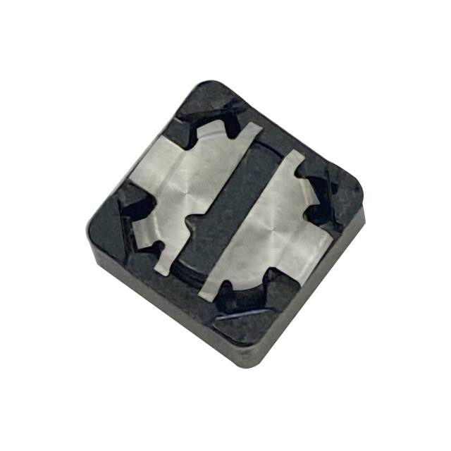
SCOPE:
This specification applies to the Pb Free high current type SMD inductors for
MSCDRI-127AH0-SERIES
Warn : This product series can’t be used in synchronous rectification circuit that is over 24V.
PRODUCT INDENTIFICATION
MSCDRI - 127A H0 - 100 M
①
②
③
④ ⑤
① Product Code
② Dimensions Code
③ AEC-Q200 Code
④ Inductance Code
⑤ Tolerance Code
(1) SHAPES AND DIMENSIONS
A: 12.0±0.5
mm
B: 12.0±0.5
mm
C: 8.0 Max.
mm
(2) ELECTRICAL SPECIFICATIONS
SEE TABLE 1
TEST INSTRUMENTS
L
: HP 4284A PRECISION LCR METER (or equivalent)
RDC : CHROMA MODEL 16502 MILLIOHMMETER (or equivalent)
(3) CHARACTERISTICS
(3)-1 Operate temperature range ...... -40℃~+155℃
(Including self temp. rise)
MAG.LAYERS
MSCDRI-127AH0-SERIES
Page-1/8
�TABLE 1
MAGLAYERS
Inductance
Percent
PT/NO.
L(μH)
Tolerance
MSCDRI-127AH0-100□
10
MSCDRI-127AH0-120□
Test
Resistance
Rated DC Current
Frequency
RDC(Ω)Max.
Isat(A)
Irms(A)
M,N
100kHz/0.25V
21.6m
7.8
5.4
100
12
M,N
100kHz/0.25V
24.3m
7.3
4.9
120
MSCDRI-127AH0-150□
15
M,N
100kHz/0.25V
27.0m
6.5
4.5
150
MSCDRI-127AH0-180□
18
M,N
100kHz/0.25V
39.2m
6.0
3.9
180
MSCDRI-127AH0-220□
22
M,N
100kHz/0.25V
43.2m
5.3
3.6
220
MSCDRI-127AH0-270□
27
M,N
100kHz/0.25V
53.1m
4.8
3.3
270
MSCDRI-127AH0-330□
33
M,N
100kHz/0.25V
64.8m
4.3
3.0
330
MSCDRI-127AH0-470□
47
M,N
100kHz/0.25V
0.10
3.8
2.5
470
MSCDRI-127AH0-560□
56
M,N
100kHz/0.25V
0.11
3.4
2.35
560
MSCDRI-127AH0-680□
68
M,N
100kHz/0.25V
0.14
3.1
2.10
680
MSCDRI-127AH0-820□
82
M,N
100kHz/0.25V
0.16
2.7
1.95
820
MSCDRI-127AH0-101□
100
M,N
100kHz/0.25V
0.22
2.5
1.70
101
MSCDRI-127AH0-121□
120
M,N
100kHz/0.25V
0.25
2.3
1.60
121
MSCDRI-127AH0-151□
150
M,N
100kHz/0.25V
0.28
2.0
1.42
151
MSCDRI-127AH0-181□
180
M,N
100kHz/0.25V
0.35
1.9
1.30
181
MSCDRI-127AH0-221□
220
M,N
100kHz/0.25V
0.39
1.7
1.16
221
MSCDRI-127AH0-271□
270
M,N
100kHz/0.25V
0.51
1.6
1.06
271
MSCDRI-127AH0-281□
280
M,N
100kHz/0.25V
0.51
1.6
1.06
281
MSCDRI-127AH0-331□
330
M,N
100kHz/0.25V
0.64
1.4
0.95
331
MSCDRI-127AH0-391□
390
M,N
100kHz/0.25V
0.70
1.3
0.88
391
MSCDRI-127AH0-471□
470
M,N
100kHz/0.25V
0.98
1.1
0.79
471
Marking
※ □ specify the inductance tolerance,M(±20%),N(±30%)
※ Isat: Based on inductance change (△L/Lo: drop 25% Max.) @ambient temperature 25℃
Irms: Based on temperature rise (△T: 40℃ Typ.)
Rated DC Current: The less value which is Isat or Irms.
MAG.LAYERS
MSCDRI-127AH0-SERIES
Page-2/8
�(4) RELIABILITY TEST METHOD
ELECTRICAL
TEST ITEM
SPECIFICATION
TEST DETAILS
Temperature
△L/L20℃≦±10%
The test shall be performed after the sample has stabilized in
characteristics
0~2000 ppm/℃
an ambient temperature of -20 to +85℃,and the value
calculated based on the value applicable in a normal
temperature and narmal humidity shall be △L/L20℃≦±10%.
MECHANICAL
TEST ITEM
Substrate bending
SPECIFICATION
TEST DETAILS
△L/Lo≦±5%
The sample shall be soldered onto the printed circuit board
There shall be
in figure 1 and a load applied unitil the figure in the arrow
no mechanical
direction is made approximately 3mm.
damage or elec-
60 sec minimum holding time.
trical damage.
PCB dimension shall the page 7/9
F(Pressurization)
Ivy
PRESSURE ROD
figure-1
Flammability
Burning stops within 10 seconds on a vertical specimen; drips of
particles allowed as long as they are not inflamed.
There shall be
no other
damage or
problems.
Terminal Strength
With the component mounted on a PCB obtained from the
Supplier with the device to be tested,apply a 17.7 N (1.8 Kg) force
to the side of a device being tested. This force shall be applied for
60 +1 seconds.
There shall be
no other
damage or
problems.
Mechanical Shock
100g's/6ms/Half-sine/12.3ft/sec
△L/Lo≦±5%
There shall be
no mechanical
damage.
MAG.LAYERS
MSCDRI-127AH0-SERIES
Page-3/8
�MECHANICAL
TEST ITEM
Vibration
SPECIFICATION
△L/Lo≦±5%
5g's for 20 minutes, 12 cycles each of 3 orientations.
Test from 10-2000 Hz.
There shall be
no mechanical
damage.
Solderability
New solder
Flux (rosin, isopropyl alcohol{JIS-K-1522}) shall be coated
More than 90%
over the whole of the sample before hard, the sample shall
then be preheated for about 2 minutes in a temperature of
130~150℃ and after it has been immersed to a depth 0.5mm
below for 3±1 seconds fully in molten solder M705 with
a temperature of 245±5℃.
More than 90% of the electrode sections shall be couered
with new solder smoothly when the sample is taken out of
the solder bath.
There shall be
Soldering heat
no damage or
(reflow soldering)
problems.
Temperature profile of reflow soldering
Sodering temperature (℃)
Resistance to
300
soldering
(Peak temperature 260±5℃ 10 sec)
250
200
150
30 sec Min
(230+0 ℃)
Pre-heating
Slow cooling
(Stored at room
temperature)
100
150 ~ 180℃
50
2 min
10
sec.
2 min. or more
Solder temperature : 260 ±5℃
Dip time: 10 ±1 seconds
The chip shall not crack.
More than 75% of the terminal electrode shall
be covered with solder.
MAG.LAYERS
MSCDRI-127AH0-SERIES
Page-4/8
�ENVIROMENT CHARACTERISTICS
TEST ITEM
High temperature
SPECIFICATION
△L/Lo≦±5%
storage
1000hrs.at rated operating temperature (e.g. 155°C part
can be stored for 1000hrs.@ 155°C.Same applies for 125°C
There shall be
and 105°C. Unpowered. Measurement at 24±4 hours after test
no mechanical
conclusion.
damage.
△L/Lo≦±5%
Temperature
1000cycles (-40°C to +155°C).Note: If 105°C part or 125°C
part the 1000cycles will be at that temperature.
Cycling
Operational Life
There shall be
Measurement at 24±4hours after test conclusion. 30min
no other dama-
maximum dwell time at each temperature extreme.1min.
ge of problems
maximum transition time.
△L/Lo≦±5%
1000hrs. @155°C. If 105°C or 125°C part will be
Tested at that temperature. Measurement at 24±4 hours after test
conclusion
There shall be
no mechanical
damage.
Biased Humidity
△L/Lo≦±5%
1000hours 85°C/85%RH. Unpowered.Measurement
at 24±4hours after test conclusion.
There shall be
no mechanical
damage.
Test conditions:
The sample shall be reflow soldered onto the printed circuit board in every test.
MAG.LAYERS
MSCDRI-127AH0-SERIES
Page-5/8
�(5) LAND DIMENSION (Ref.)
PCB: GLASS EPOXY t=1.6mm
(5)-1 LAND PATTERN DIMENSIONS
(STANDARD PATTERN)
Unit:mm
12.6
7.0
2.8
5.4
(5)-2 SUBSTRATE BENDING TEST BENDING TEST BOARD
MAG.LAYERS
MSCDRI-127AH0-SERIES
Page-6/8
�(6) PACKAGING
(6)-1 CARRIER TAPE DIMENSIONS (mm)
(6)-2 TAPING DIMENSIONS (mm)
Unreeling
Direction
MAG.LAYERS
MSCDRI-127AH0-SERIES
Page-7/8
�(6)-3 REEL DIMENSIONS (mm)
(6)-4 QUANTITY
500 pcs/Reel
The products are packaged so that no damage will be sustained.
Please note that the contents may change without any prior notice due to reasons such as
upgrading.
MAG.LAYERS
MSCDRI-127AH0-SERIES
Page-8/8
�
MSCDRI-127A-220M-RU 价格&库存
很抱歉,暂时无法提供与“MSCDRI-127A-220M-RU”相匹配的价格&库存,您可以联系我们找货
免费人工找货