0
登录后你可以
  • 下载海量资料
  • 学习在线课程
  • 观看技术视频
  • 写文章/发帖/加入社区
会员中心
创作中心
发布
  • 发文章

  • 发资料

  • 发帖

  • 提问

  • 发视频

创作活动
SD14-221-R

SD14-221-R

  • 厂商:

    EATON(伊顿)

  • 封装:

    非标准

  • 描述:

    固定电感器 Nonstandard 220µH ±20% 258mA 3.77Ω

  • 详情介绍
  • 数据手册
  • 价格&库存
SD14-221-R 数据手册
Technical Data PM4311 Effective August 2017 Supersedes March 2007 SD Low profile metalized shielded drum core power inductors Applications • • • • • • Digital cameras Media players Mobile phones Hand held equipment PCMCIA cards GPS systems Environmental data • Product features • • • • • Six sizes of shielded drum core inductors with low profiles (as low as 1.0mm) and high power density Inductance range from .47 uH to 1000 uH Current range from 0.88 A to 6.0 A Ferrite shielded, low EMI Ferrite core material • • Storage temperature range (component): -40 °C to +125 °C Operating temperature range: -40 °C to +125 °C (ambient plus self-temperature rise) Solder reflow temperature: J-STD-020 (latest revision) compliant Pb HF FREE HALOGEN  Technical Data PM4311 Effective August 2017 Product specifications Part Number OCL (1) +/-20% (µH) 0.453 1.119 1.563 2.081 3.339 4.893 6.743 8.889 10.07 15.55 22.21 32.20 46.63 70.01 83.48 102.0 149.2 222.2 330.4 468.3 0.490 1.21 1.69 2.25 3.61 4.41 6.25 8.41 10.89 15.21 22.09 32.49 47.61 68.89 Part Marking Irms (2) (A) Isat (3) (A) SD10-R47-R SD10-1R0-R SD10-1R5-R SD10-2R2-R SD10-3R3-R SD10-4R7-R SD10-6R2-R SD10-8R2-R SD10-100-R SD10-150-R SD10-220-R SD10-330-R SD10-470-R SD10-680-R SD10-820-R SD10-101-R SD10-151-R SD10-221-R SD10-331-R SD10-471-R SD12-R47-R SD12-1R2-R SD12-1R5-R SD12-2R2-R SD12-3R3-R SD12-4R7-R SD12-6R2-R SD12-8R2-R SD12-100-R SD12-150-R SD12-220-R SD12-330-R SD12-470-R SD12-680-R Rated Inductance (µH) 0.470 1.00 1.50 2.20 3.30 4.70 6.20 8.20 10.0 15.0 22.0 33.0 47.0 68.0 82.0 100 150 220 330 470 0.470 1.20 1.50 2.20 3.30 4.70 6.20 8.20 10.0 15.0 22.0 33.0 47.0 68.0 A B C D E F G H J K L M N O P Q R S T U A B C D E F G H J K L M N O 2.59 1.93 1.60 1.35 1.24 1.04 0.94 0.800 0.760 0.613 0.498 0.412 0.337 0.301 0.258 0.225 0.200 0.161 0.130 0.117 3.19 2.62 2.19 1.83 1.55 1.46 1.21 1.02 0.938 0.782 0.628 0.519 0.428 0.341 SD12-820-R SD12-101-R SD12-151-R SD12-221-R SD12-331-R SD12-471-R SD12-681-R SD12-821-R SD12-102-R 82.0 100 150 220 330 470 680 820 1000 82.81 98.0 151.3 222.0 334.9 462.3 670.8 800.9 992.3 P Q R S T U V W X 0.326 0.308 0.251 0.229 0.186 0.167 0.149 0.129 0.121 (1) Open Circuit Inductance Test Parameters: 100 kHz, 0.25 Vrms, 0.0 Adc. (2) RMS current for an approximate ∆T of 40 °C without core loss. It is recommended that the temperature of the part not exceed +125 °C. (3) SD10,12,18,25 Peak current for approximate 30% rolloff at +20 °C. SD14 Peak current for approximate 20% roll off at +20 °C. 2 www.eaton.com/electronics 3.54 2.25 1.91 1.65 1.31 1.08 0.92 0.800 0.752 0.605 0.506 0.420 0.349 0.285 0.261 0.236 0.195 0.160 0.131 0.110 3.86 2.45 2.08 1.80 1.42 1.29 1.08 0.931 0.818 0.692 0.574 0.474 0.391 0.325 DCR (4) (Ω) Typ. 0.0249 0.0448 0.0653 0.0912 0.1078 0.1535 0.218 0.2607 0.336 0.4429 0.6718 0.9807 1.47 1.84 2.50 3.29 4.15 6.41 9.83 12.10 0.0246 0.0366 0.0521 0.0747 0.1043 0.1177 0.1699 0.2399 0.2844 0.4089 0.6338 0.9289 1.37 2.16 Volt u-sec Typ. 2.1 3.3 3.9 4.5 5.7 6.9 8.1 9.3 9.9 12.3 14.7 17.7 21.3 26.1 28.5 31.5 38.1 46.5 56.7 67.5 2.84 4.47 5.28 6.09 7.71 8.53 10.15 11.77 13.40 15.83 19.08 23.14 28.01 33.70 0.297 0.273 0.220 0.181 0.148 0.126 0.104 0.095 0.086 2.36 2.64 3.96 4.76 7.25 8.95 11.30 14.93 17.20 36.95 40.19 49.94 60.49 74.30 87.29 105 115 128 (4) DCR limits @ +20 °C. 5) Applied Volt-Time product (V-us) across the inductor at 100 kHz necessary to generate a core loss equal to 10% of the total losses for 40 °C temperature rise. SD Low profile metalized shielded drum core power inductors Technical Data PM4311 Effective August 2017 Product specifications Part Number Rated Inductance (µH) OCL (1) +/-20% (µH) Part Marking Irms (2) (A) Isat (3) (A) DCR (4) (Ω) Typ. Volt u-sec Typ. SD14-R58-R SD14-R87-R SD14-1R2-R SD14-1R5-R SD14-2R0-R SD14-2R5-R SD14-3R2-R SD14-4R5-R SD14-6R9-R SD14-8R8-R SD14-100-R SD14-150-R SD14-220-R SD14-330-R SD14-470-R SD14-680-R SD14-820-R SD14-101-R SD14-151-R SD14-221-R SD14-331-R SD14-471-R SD14-681-R SD14-821-R SD14-102-R SD18-R47-R SD18-R82-R SD18-1R2-R SD18-1R5-R SD18-2R2-R SD18-3R3-R SD18-4R7-R SD18-6R2-R SD18-8R2-R SD18-100-R SD18-150-R SD18-220-R SD18-330-R SD18-470-R SD18-680-R SD18-820-R SD18-101-R SD18-151-R SD18-221-R SD18-331-R SD18-471-R SD18-681-R SD18-821-R SD18-102-R 0.58 0.87 1.2 1.5 2 2.5 3.2 4.5 6.9 8.8 10 15 22 33 47 68 82 100 150 220 330 470 680 820 1000 0.47 0.82 1.20 1.50 2.20 3.30 4.70 6.20 8.20 10.0 15.0 22.0 33.0 47.0 68.0 82.0 100 150 220 330 470 680 820 1000 0.61 0.88 1.23 1.63 2.09 2.62 3.19 4.53 6.98 8.88 9.93 14.68 21.93 32.55 47.57 68.21 83 99.25 152.4 222 335.1 471.4 683.3 823.4 1008 0.49 0.81 1.21 1.69 2.25 3.61 4.41 6.25 8.41 10.89 15.21 22.09 32.49 47.61 68.89 82.81 102.01 151.29 222.01 334.89 479.61 681.21 823.69 1004 A B C D E F G H J K L M N O P Q R S T U V W X Y Z A B C D E F G H J K L M N O P Q R S T U V W X Y 3.52 3.2 2.7 2.53 2.37 2.05 1.94 1.64 1.35 1.14 1.1 0.98 0.806 0.654 0.525 0.474 0.408 0.386 0.315 0.258 0.206 0.173 0.156 0.134 0.126 3.58 3.24 2.97 2.73 2.55 2.07 1.77 1.61 1.38 1.28 1.06 0.876 0.715 0.578 0.514 0.446 0.419 0.345 0.296 0.248 0.201 0.167 0.145 0.136 4.84 3.96 3.35 2.91 2.56 2.29 2.08 1.74 1.41 1.25 1.18 0.969 0.793 0.651 0.538 0.449 0.407 0.373 0.301 0.249 0.203 0.171 0.142 0.129 0.117 4.63 3.60 2.95 2.49 2.16 1.71 1.54 1.30 1.12 0.982 0.831 0.689 0.568 0.470 0.390 0.356 0.321 0.263 0.217 0.177 0.148 0.124 0.113 0.102 0.0220 0.0243 0.0344 0.0390 0.0445 0.0595 0.0663 0.0935 0.1363 0.1913 0.2058 0.2609 0.3853 0.5852 0.9055 1.11 1.50 1.68 2.52 3.77 5.92 8.34 10.3 13.9 15.8 0.0201 0.0247 0.0294 0.0345 0.0398 0.0605 0.0824 0.1000 0.1351 0.1584 0.2278 0.3366 0.5057 0.7732 0.9798 1.30 1.47 2.18 2.95 4.20 6.39 9.28 12.35 14.01 3.38 4.13 4.88 5.63 6.38 7.1 7.9 9.4 11.6 13.1 13.9 16.9 20.6 25.1 30.4 36 40 44 54 66 81 96 115 126 140 2.35 3.02 3.70 4.37 5.04 6.38 7.06 8.40 9.74 11.09 13.10 15.79 19.15 23.18 27.89 30.58 33.94 41.33 50.06 61.49 73.58 87.70 96.43 107 (1) Open Circuit Inductance Test Parameters: 100 kHz, 0.25 Vrms, 0.0 Adc. (2) RMS current for an approximate ∆T of 40 °C without core loss. It is recommended that the temperature of the part not exceed +125 °C. (3) SD10,12,18,25 Peak current for approximate 30% rolloff at +20 °C. SD14 Peak current for approximate 20% roll off at +20 °C. (4) DCR limits @ +20 °C. 5) Applied Volt-Time product (V-us) across the inductor at 100 kHz necessary to generate a core loss equal to 10% of the total losses for 40 °C temperature rise. www.eaton.com/electronics 3 SD Low profile metalized shielded drum core power inductors Technical Data PM4311 Effective August 2017 Product specifications Part Number SD20-R47-R SD20-1R2-R SD20-1R5-R SD20-2R2-R SD20-3R3-R SD20-4R7-R SD20-6R2-R SD20-8R2-R SD20-100-R SD20-150-R SD20-220-R SD20-330-R SD20-470-R SD20-680-R SD20-820-R SD20-101-R SD20-151-R SD20-221-R SD20-331-R SD20-471-R SD20-681-R SD20-821-R SD20-102-R SD25-R47-R SD25-R82-R SD25-1R2-R SD25-1R5-R SD25-2R2-R SD25-3R3-R SD25-4R7-R SD25-6R8-R SD25-8R2-R SD25-100-R SD25-150-R SD25-220-R SD25-330-R SD25-470-R SD25-680-R SD25-820-R SD25-101-R SD25-151-R SD25-221-R SD25-331-R SD25-471-R SD25-681-R SD25-821-R SD25-102-R Rated Inductance (µH) 0.47 1.20 1.50 2.20 3.30 4.70 6.20 8.20 10.0 15.0 22.0 33.0 47.0 68.0 82.0 100 150 220 330 470 680 820 1000 0.47 0.82 1.20 1.50 2.20 3.30 4.70 6.80 8.20 10.0 15.0 22.0 33.0 47.0 68.0 82.0 100 150 220 330 470 680 820 1000 OCL (1) +/-20% (µH) 0.490 1.21 1.69 2.25 3.61 4.41 6.25 8.41 9.61 15.21 22.09 32.49 47.61 68.89 82.81 98.01 151.3 222.0 327.6 470.9 681.2 823.7 1004.9 0.466 0.770 1.15 1.61 2.14 3.43 5.03 6.93 7.99 10.35 14.45 22.81 33.07 47.89 68.64 82.17 100.79 148.4 222.4 332.2 472.4 677.2 826.7 1003.4 (1) Open Circuit Inductance Test Parameters: 100 kHz, 0.25 Vrms, 0.0 Adc. (2) RMS current for an approximate ∆T of 40 °C without core loss. It is recommended that the temperature of the part not exceed +125 °C. (3) SD10,12,18,25 Peak current for approximate 30% roll off at +20 °C. SD14 Peak current for approximate 20% roll off at +20 °C. 4 www.eaton.com/electronics Part Marking Irms (2) Amperes Isat (3) Amperes A B C D E F G H J K L M N O P Q R S T U V W X A B C D E F G H J K L M N O P Q R S T U V W X Y 3.59 3.07 2.88 2.45 2.17 2.05 1.89 1.61 1.53 1.25 1.12 0.913 0.745 0.610 0.576 0.495 0.435 0.356 0.294 0.263 0.216 0.204 0.172 3.88 3.58 3.33 3.12 2.93 2.64 2.39 2.19 1.92 1.80 1.67 1.34 1.11 0.919 0.741 0.713 0.670 0.553 0.446 0.359 0.293 0.262 0.230 0.216 4.00 2.55 2.15 1.87 1.47 1.33 1.12 0.966 0.903 0.718 0.596 0.491 0.406 0.337 0.308 0.283 0.228 0.188 0.155 0.129 0.107 0.098 0.088 6.00 4.67 3.81 3.23 2.80 2.21 1.83 1.56 1.45 1.27 1.08 0.857 0.711 0.592 0.482 0.441 0.398 0.328 0.268 0.219 0.184 0.154 0.139 0.126 DCR (4) (Ω) Typ. 0.0200 0.0275 0.0312 0.0429 0.0547 0.0612 0.0720 0.1000 0.1100 0.1655 0.2053 0.3100 0.4650 0.6947 0.7785 1.06 1.37 2.04 2.99 3.74 5.56 6.22 8.73 0.0177 0.0208 0.0240 0.0274 0.0311 0.0384 0.0467 0.0556 0.0724 0.0824 0.0956 0.1478 0.2149 0.3156 0.4850 0.5242 0.5937 0.8723 1.34 2.07 3.10 3.88 5.04 5.70 Volt u-sec Typ. 2.28 3.58 4.23 4.88 6.18 6.83 8.13 9.43 10.08 12.68 15.28 18.53 22.43 26.98 29.58 32.18 39.98 48.43 58.83 70.53 84.83 93.28 103 2.13 2.74 3.34 3.95 4.56 5.78 6.99 8.21 8.82 10.03 11.86 14.90 17.94 21.58 25.84 28.27 31.31 38.00 46.51 56.85 67.79 81.17 89.68 98.80 (4) DCR limits @ +20 °C. 5) Applied Volt-Time product (V-us) across the inductor at 100 kHz necessary to generate a core loss equal to 10% of the total losses for 40 °C temperature rise. SD Low profile metalized shielded drum core power inductors Technical Data PM4311 Effective August 2017 Dimensions-mm RECOMMENDED PCB LAYOUT TOP VIEW Pin # 1 identifier 2 PAD LAYOUT SIDE VIEW 1 SCHEMATIC 1 Series SD10 SD12 SD14 SD18 SD20 SD25 5.950 2.975 2 2.575 2 HT 2.975 R2.250 5.15 (see chart below) 5.2 Max 1 2.975 R2.250 1.0 1.5 Typ. Ref. 2 5.950 9 5.95 9 5.2 Max a Part marking (Note A) 4 PAD LAYOUT BOTTOM VIEW A) Part Marking: Line 1: (1st digit indicates the inductance value per part marking designator in chart above) (2nd digit is a bi-weekly production date code) (3rd digit is the last digit of the year produced) Line 2: XX (indicates the product size code) HT 1.0mm max 1.2mm max 1.45mm max 1.8mm max 2.0mm max 2.5mm max Do not route traces or vias underneath the inductor Packaging Information SD10 4.00 2.00 ± 0.05 1.5 Dia min. 1.5 Dia. +0.1/-0.0 A 1.75 1 12.0 +/-0.3 0 Bo ACTUAL SIZE SD10 5.50 2 Ao=5.45mm Bo=5.45mm Ko=1.20mm Ko A Ao Parts packaged on 13" Diameter reel, 3,800 parts per reel. 8.0 SECTION A-A Direction of feed SD12/14/18 4.00 2.00 ± 0.05 1.5 Dia min. 1.5 Dia. +0.1/-0.0 1.75 A ACTUAL SIZE SD12 1 12.0 +/-0.3 Bo 5.50 ACTUAL SIZE SD18 2 Ao=5.45mm Bo=5.45mm Ko=2.00mm ACTUAL SIZE SD14 Ko A Ao Parts packaged on 13" Diameter reel, 3,800 parts per reel. 8.0 SECTION A-A Direction of feed SD20/25 4.00 2.00 ± 0.05 1.5 Dia min. 1.5 Dia. +0.1/-0.0 1.75 A 1 12.0 +/-0.3 0 Bo 5.50 2 Ao=5.45mm Bo=5.45mm Ko=2.70mm Ko Ao SECTION A-A ACTUAL SIZE SD20 ACTUAL SIZE SD25 A 8.0 0 Direction of feed Parts packaged on 13" Diameter reel, 2,900 parts per reel. Dimensions are in millimeters. www.eaton.com/electronics 5 SD Low profile metalized shielded drum core power inductors Technical Data PM4311 Effective August 2017 Temperature rise vs current SD10-471 100.0 90.0 90.0 Temperature Rise (Deg. C) Temperature Rise (Deg. C) SD10-220 100.0 80.0 70.0 60.0 50.0 40.0 30.0 20.0 80.0 70.0 60.0 50.0 40.0 30.0 20.0 10.0 10.0 0.0 0.00 0.10 0.20 0.30 0.40 0.50 0.60 0.70 0.0 0.00 0.80 0.05 0.09 0.14 Idc (A) 100.0 90.0 90.0 Temperature Rise (Deg. C) Temperature Rise (Deg. C) 0.23 SD12-470 SD12-330 100.0 80.0 70.0 60.0 50.0 40.0 30.0 20.0 10.0 80.0 70.0 60.0 50.0 40.0 30.0 20.0 10.0 0.0 0.00 0.10 0.20 0.30 0.40 0.50 0.60 0.70 0.0 0.00 0.80 0.10 0.20 0.30 Idc (A) 0.40 0.50 0.60 0.70 Idc (A) SD14-102 SD14-150 100.0 100.0 90.0 Temperature Rise (Deg. C) 90.0 Temperature Rise (Deg. C) 0.18 Idc (A) 80.0 70.0 60.0 50.0 40.0 30.0 20.0 10.0 80.0 70.0 60.0 50.0 40.0 30.0 20.0 10.0 0.0 0.00 0.20 0.40 0.60 0.80 1.00 1.20 0.0 0.000 0.020 0.040 0.060 0.080 0.100 0.120 0.140 0.160 0.180 0.200 1.40 Idc (A) Idc (A) SD18-100 SD18-101 100.0 100.0 Temperature Rise (Deg. C) Temperature Rise (Deg. C) 90.0 80.0 70.0 60.0 50.0 40.0 30.0 20.0 90.0 80.0 70.0 60.0 50.0 40.0 30.0 20.0 10.0 10.0 0.0 0.00 0.0 0.0 0.2 0.4 0.6 0.8 1.0 1.2 1.4 1.6 1.8 2.0 0.10 0.20 0.30 100.0 100.0 90.0 90.0 Temperature Rise (Deg. C) Temperature Rise (Deg. C) 0.50 0.60 0.70 0.80 SD20-101 SD20-100 80.0 70.0 60.0 50.0 40.0 30.0 20.0 10.0 80.0 70.0 60.0 50.0 40.0 30.0 20.0 10.0 0.0 0.0 0.4 0.8 1.2 Idc (A) 6 0.40 Idc (A) Idc (A) www.eaton.com/electronics 1.6 2.0 2.4 0.0 0.00 0.10 0.20 0.30 0.40 Idc (A) 0.50 0.60 0.70 0.80 SD Low profile metalized shielded drum core power inductors Technical Data PM4311 Effective August 2017 Temperature rise vs current SD25-100 SD25-101 100.0 100.0 Temperature Rise (Deg. C) Temperature Rise (Deg. C) 90.0 80.0 70.0 60.0 50.0 40.0 30.0 20.0 90.0 80.0 70.0 60.0 50.0 40.0 30.0 20.0 10.0 10.0 0.0 0.00 0.0 0.0 0.5 1.0 1.5 2.0 2.5 3.0 0.20 0.40 0.60 0.80 1.00 1.20 Idc (A) Idc (A) Inductance Characteristics OCL vs Isat SD12 100 100 90 90 80 80 70 70 OCL (%) OCL (%) OCL vs Isat SD10 60 50 40 50 40 30 30 20 20 10 10 0 0 10 20 30 40 50 60 70 80 90 100 110 120 130 0 140 0 10 20 30 40 50 70 % of Isat OCL vs Isat SD14 OCL vs Isat SD18 100 100 90 90 80 80 70 70 60 50 80 90 100 110 120 60 50 40 40 30 30 20 20 10 10 0 0 10 20 30 40 50 60 70 80 90 100 110 120 0 130 0 10 20 30 40 50 60 70 80 90 100 110 120 130 140 150 160 140 150 % of Isat % of Isat OCL vs Isat SD20 OCL vs Isat SD25 100 100 90 90 80 80 70 70 OCL (%) OCL (%) 60 % of Isat OCL (%) OCL (%) 60 60 50 60 50 40 40 30 30 20 20 10 10 0 0 0 10 20 30 40 50 60 70 80 90 % of Isat 100 110 120 130 140 150 160 170 0 10 20 30 40 50 60 70 80 90 100 110 120 130 % of Isat www.eaton.com/electronics 7 Technical Data PM4311 Effective August 2017 SD Low profile metalized shielded drum core power inductors Core loss % of Losses from Irms (maximum) Irms DERATING WITH CORE LOSS % of applied volt u-seconds 8 www.eaton.com/electronics SD Low profile metalized shielded drum core power inductors Technical Data PM4311 Effective August 2017 Solder Reflow Profile TP tP Max. Ramp Up Rate = 3°C/s Max. Ramp Down Rate = 6°C/s Temperature TL 25°C Preheat A T smax t TC -5°C Table 1 - Standard SnPb Solder (Tc) Volume mm3 220°C 220°C Table 2 - Lead (Pb) Free Solder (T c) Tsmin ts Package Thickness 2.5mm Time 25°C to Peak Volume mm3 2000 260°C 245°C 245°C Time Reference JDEC J-STD-020 Profile Feature Preheat and Soak • Temperature min. (Tsmin) • Temperature max. (Tsmax) • Time (Tsmin to Tsmax) (ts) Average ramp up rate Tsmax to Tp Liquidous temperature (TL) Time at liquidous (tL) Peak package body temperature (TP)* Time (tp)** within 5 °C of the specified classification temperature (Tc) Average ramp-down rate (Tp to Tsmax) Time 25°C to Peak Temperature Standard SnPb Solder 100°C Lead (Pb) Free Solder 150°C 150°C 200°C 60-120 Seconds 60-120 Seconds 3°C/ Second Max. 3°C/ Second Max. 183°C 60-150 Seconds 217°C 60-150 Seconds Table 1 Table 2 20 Seconds** 30 Seconds** 6°C/ Second Max. 6°C/ Second Max. 6 Minutes Max. 8 Minutes Max. * Tolerance for peak profile temperature (Tp) is defined as a supplier minimum and a user maximum. ** Tolerance for time at peak profile temperature (tp) is defined as a supplier minimum and a user maximum. Life Support Policy: Eaton does not authorize the use of any of its products for use in life support devices or systems without the express written approval of an officer of the Company. Life support systems are devices which support or sustain life, and whose failure to perform, when properly used in accordance with instructions for use provided in the labeling, can be reasonably expected to result in significant injury to the user. Eaton reserves the right, without notice, to change design or construction of any products and to discontinue or limit distribution of any products. Eaton also reserves the right to change or update, without notice, any technical information contained in this bulletin. Eaton Electronics Division 1000 Eaton Boulevard Cleveland, OH 44122 United States www.eaton.com/electronics © 2017 Eaton All Rights Reserved Printed in USA Publication No. PM4311 August 2017 Eaton is a registered trademark. All other trademarks are property of their respective owners.
SD14-221-R
1. 物料型号:文档列出了不同型号的电感器,包括SD10、SD12、SD14、SD18、SD20和SD25系列。

2. 器件简介:这些电感器适用于数字相机、媒体播放器、手机、手持设备、PCMCIA卡和GPS系统等。

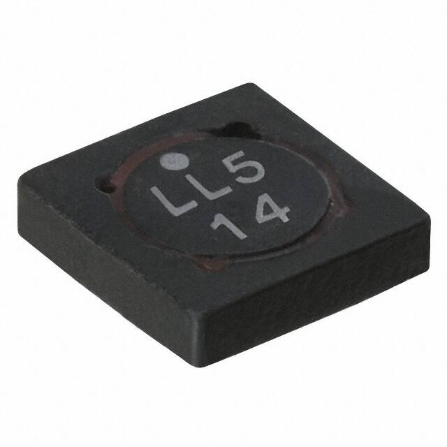
3. 引脚分配:文档提供了电感器的推荐PCB布局,包括顶部视图、底部视图和侧视图,以及标识符和引脚#1的示意图。

4. 参数特性: - 工作温度范围:-40°C至+125°C(环境加自温升) - 电感范围:从0.47微亨利到1000微亨利 - 电流范围:从0.88安培到6.0安培 - 直流电阻(DCR):典型值从0.0177欧姆到2.50欧姆 - 饱和电流(Isat):不同型号的电感器在+20°C时的峰值电流,以30%或20%的下降率

5. 功能详解:文档详细描述了电感器的电气特性,包括额定电感、开路电感(OCL)、工作电流(Irms)、饱和电流(Isat)和直流电阻(DCR)。

6. 应用信息:电感器适用于需要高功率密度和低电磁干扰(EMI)的应用。

7. 封装信息:提供了不同系列电感器的尺寸信息,包括推荐PCB布局和包装信息。

8. 环境数据:存储温度范围为-40°C至+125°C,符合RoHS标准。

9. 温度上升与电流关系:图表显示了不同型号电感器在不同直流电流下的温升情况。

10. 电感特性:图表展示了开路电感(OCL)与饱和电流(Isat)的关系。

11. 核心损耗:文档提供了有关电感器在不同工作条件下的核心损耗数据。

12. 焊接回流曲线:提供了焊接时的最大升温速率、最大降温速率和不同封装厚度的推荐温度。
SD14-221-R 价格&库存

很抱歉,暂时无法提供与“SD14-221-R”相匹配的价格&库存,您可以联系我们找货

免费人工找货