Technical Data 4109
Effective October 2015
Supersedes August 2006
HC2
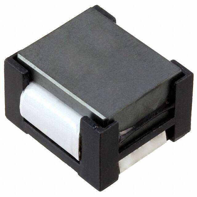
High current power inductors
Applications
•
Distributed power systems DC-DC converters
•
General-purpose low voltage supplies
•
Computer systems
•
Servers
•
Point of Load (POL) converters
•
Industrial Equipment
•
Networking/Telecom power supplies
Environmental data
Product description
•
Storage temperature range (component): 40°C to +125°C
•
Compact footprint
•
•
Designed for high density, high current/low
voltage applications
Operating temperature range: -40°C to +125°C
(ambient + self-temperature rise).
•
•
Foil technology that adds higher reliability factor
over the traditional magnet wire used for higher
frequency circuit designs
Solder reflow temperature: J-STD-020D
compliant
•
Frequency Range up to 1MHz
Pb
�HC2
High current power inductors
Technical Data 4109
Effective October 2015
Product specifications
Part number
Part number
(Tape and reel)
OCL1 (μH) ±20%
lrms2 amps
lsat3 amps
DCR (Ω)4
maximum @ 20°C
Volt-μsec5
(V-μs)
HC2-R47-R
HC2-R47TR-R
.52
52.9
63.75
.0006
6.87
HC2-R68-R
HC2-R68TR-R
.63
52.9
50.00
.0006
6.87
HC2-1R0-R
HC2-1R0TR-R
1.15
33.0
42.50
.0013
10.31
HC2-2R2-R
HC2-2R2TR-R
2.00
24.3
31.90
.0023
13.75
HC2-4R7-R
HC2-4R7TR-R
4.55
17.0
21.25
.0046
20.62
HC2-6R0-R
HC2-6R0TR-R
6.00
17.0
16.50
.0046
20.62
1. Open Circuit Inductance Test Parameters: 300kHz, 0.250 Vrms, 0.0 Adc
2. DC current for an approximate temperature change of 40°C without core loss. Derating is necessary
for AC currents. PCB layout, trace thickness and width, air-flow and proximity of other heat
generating components will affect the temperature rise. It is recommended that the temperature
of the part not exceed 125°C under worst case operating conditions verified in the end application.
3. Peak current for approximately 30% rolloff.
4. Values @ 20°C
5. Applied Volt-Time product (V-μs) across the inductor. This value represents the applied V-μs at
300KHz neccessary to generate a core loss equal to 10% of the total losses for 40°C temperature rise.
Dimensions–mm
RECOMMENDED PCB PAD LAYOUT
TOP VIEW
10.00
1 HC2 - XXX
wwllyy R
2
19.0
max
19.00
9.5
typ
5.50
5.50
19.2
max
FRONT VIEW
SCHEMATIC
1
12.7
max
2
3.5
typ
2.3
typ
Packaging information (mm)
Bulk packaging: 45 parts per tray
Tape and reel packaging: 110 parts per 13” diameter reel
1.5Dia +0.10
-0.00
4.0
2.0Dia
min
2.0
A
1.75
R0.5 ref
20.2
Ao= 19.3mm
Bo= 19.3mm
Ko= 12.9mm
B
Bo
Ko
SECTION A-A
2
www.eaton.com/elx
HC2-xxx
wwllyy R
Ao
40.4
+/-0.1
0
A
32
User direction of feed
44.0
+/-0.3
0
�HC2
High current power inductors
Technical Data 4109
Effective October 2015
Rolloff
INDUCTANCE VERSUS SATURATION CURRENT
100
90
80
% of OCL
70
60
50
40
30
20
10
0
0
20
Core loss
60
80
100
% of ISAT
120
140
160
180
200
IRMS DERATING WITH CORE LOSS
0
20
40
50
60
Hz
0K
10
Hz
Hz
0K
0K
20
0K
50
30
Hz
80
Hz
70
1M
% of Losses from Irms (maximum)
40
90
92
94
95
96
97
98
99
10
20
30
40
50
60
80
100
200
300
% of Applied Volt-μ-Seconds
400 500 600
800 1000
www.eaton.com/elx
3
�HC2
High current power inductors
Technical Data 4109
Effective October 2015
Solder reflow profile
TP
TC -5°C
tP
Max. Ramp Up Rate = 3°C/s
Max. Ramp Down Rate = 6°C/s
Temperature
TL
Preheat
A
T smax
t
Table 1 - Standard SnPb Solder (Tc)
Package
Thickness
Volume
mm3
很抱歉,暂时无法提供与“HC2-1R0-R”相匹配的价格&库存,您可以联系我们找货
免费人工找货