Technical Data DS4308
Effective August 2017
Supersedes March 2007
UP
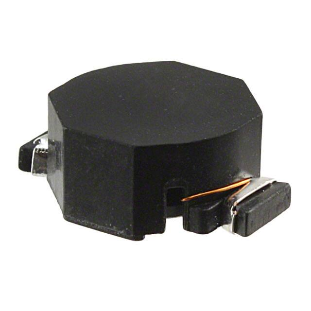
UNI-PAC™ drum core power inductors
Applications
Product features
•
•
•
•
•
•
•
Maximum power density
Ideal for applications requiring low inductance
and high current in a miniature package
Current range from 0.47 A to 19.2 A
Inductance range from 0.470 uH to 1000 uH
Protective case eliminates core breakage
Meets UL 94V-0 flammability standard
Ferrite core material
•
Buck or boost inductor
•
Workstations/servers
•
Desktop computer
•
DVD Players
•
Portable power devices
•
Base stations
•
Industrial power supplies
•
Output filter chokes
•
Test equipment instrumentation
Environmental Data
•
Storage temperature range (Component):
-40 °C to +125 °C
•
Operating temperature range: -40 °C to +125 °C
(ambient plus self-temperature rise)
•
Solder reflow temperature:
J-STD-020 (latest revision) compliant
�UP
UNI-PAC™ drum core power inductors
Technical Data DS4308
Effective August 2017
Product Specifications
Part
Number
UP1B-R47-R
UP1B-1R0-R
UP1B-1R5-R
UP1B-2R2-R
UP1B-3R3-R
UP1B-4R7-R
UP1B-6R8-R
UP1B-100-R
UP1B-150-R
UP1B-220-R
UP1B-330-R
UP1B-470-R
UP1B-680-R
UP1B-101-R
UP1B-151-R
UP1B-221-R
UP1B-331-R
UP2B-R47-R
UP2B-1R0-R
UP2B-1R5-R
UP2B-2R2-R
UP2B-3R3-R
UP2B-4R7-R
UP2B-6R8-R
UP2B-100-R
UP2B-150-R
UP2B-220-R
UP2B-330-R
UP2B-470-R
UP2B-680-R
UP2B-820-R
UP2B-101-R
UP2B-151-R
Inductance
µH (rated)
0.47
1.0
1.5
2.2
3.3
4.7
6.8
10.0
15.0
22.0
33.0
47.0
68.0
100.0
150.0
220.0
330.0
0.47
1.0
1.5
2.2
3.3
4.7
6.8
10.0
15.0
22.0
33.0
47.0
68.0
82.0
100.0
150.0
OCL (1)
µH ±20%
0.569
1.20
1.61
2.62
3.79
5.15
6.87
11.00
16.00
23.50
36.00
48.50
73.52
112.67
152.40
223.10
331.90
0.595
1.00
1.46
2.56
3.23
4.77
6.63
9.73
15.43
22.50
33.13
48.65
68.17
84.1
102.60
150
I R MS (2)
(A)
6.0
4.4
4.2
3.1
2.9
2.2
1.7
1.5
1.2
1.0
0.82
0.72
0.58
0.47
0.40
0.36
0.28
10.6
9.3
8.3
7.2
6.5
5.5
5.0
4.3
3.5
2.8
2.1
1.7
1.5
1.34
1.2
1.0
I S AT (3)
(A)
7.7
5.3
4.5
3.5
3.0
2.6
2.2
1.9
1.5
1.2
0.99
0.87
0.67
0.53
0.46
0.38
0.31
11.4
9.9
7.9
6.1
5.1
4.2
3.6
3.3
2.4
2.0
1.7
1.4
1.2
1.03
0.95
0.77
DCR (4)
Ohms max.
0.0097
0.0177
0.0200
0.0363
0.0428
0.0544
0.0897
0.1107
0.1747
0.2541
0.3670
0.4740
0.7320
1.11
1.61
1.96
3.10
0.0049
0.0065
0.0081
0.0107
0.0128
0.0165
0.0202
0.0267
0.0410
0.0617
0.0917
0.1388
0.1787
0.2235
0.2707
0.4100
UP2B-221-R
UP2B-331-R
UP2B-471-R
UP2B-681-R
UP2B-821-R
UP2B-102-R
UP3B-R47-R
UP3B-1R0-R
UP3B-1R5-R
UP3B-2R2-R
UP3B-3R3-R
UP3B-4R7-R
UP3B-6R8-R
UP3B-100-R
UP3B-150-R
UP3B-220-R
UP3B-330-R
UP3B-470-R
UP3B-680-R
UP3B-101-R
UP3B-151-R
UP3B-331-R
UP4B-R47-R
UP4B-1R0-R
UP4B-1R5-R
UP4B-2R2-R
UP4B-3R3-R
UP4B-4R7-R
UP4B-6R8-R
UP4B-100-R
UP4B-150-R
UP4B-220-R
UP4B-330-R
UP4B-470-R
UP4B-680-R
UP4B-101-R
UP4B-151-R
UP4B-221-R
UP4B-331-R
UP4B-471-R
220.0
330.0
470.0
680.0
820.0
1000.0
0.47
1.0
1.5
2.2
3.3
4.7
6.8
10.0
15.0
22.0
33.0
47.0
68.0
100.0
150.0
330.0
0.47
1.0
1.5
2.2
3.3
4.7
6.8
10.0
15.0
22.0
33.0
47.0
68.0
100.0
150.0
220.0
330.0
470.0
223
338
471
700
823
1005
0.452
1.34
2.08
3.01
3.96
5.00
7.70
11.00
16.38
23.93
33.85
51.00
69.50
101.40
152.9
332.80
0.473
0.916
1.52
2.27
3.14
5.34
6.66
9.77
15.61
22.61
34.30
48.10
69.14
99.42
146.90
221.40
330.00
470.10
0.773
0.676
0.553
0.452
0.423
0.369
16.0
12.5
10.0
9.2
8.0
6.5
5.8
4.3
3.9
3.1
2.4
1.9
1.6
1.4
1.2
0.75
19.2
17.3
13.4
12.0
11.0
8.6
8.3
6.8
5.5
4.5
3.7
3.1
2.4
2.0
1.7
1.4
1.1
0.91
0.637
0.510
0.427
0.355
0.334
0.300
25.1
15.3
12.0
10.2
9.3
7.7
6.2
5.2
4.3
3.7
3.0
2.4
2.0
1.8
1.4
0.98
51.7
37.3
28.9
23.7
20.2
15.6
14.1
11.5
9.1
7.6
6.1
5.2
4.3
3.6
3.0
2.4
2.0
1.7
0.6717
0.8783
1.31
1.97
2.24
2.96
0.0021
0.0034
0.0053
0.0074
0.0083
0.0114
0.0183
0.0260
0.0317
0.0490
0.0688
0.1082
0.1558
0.2053
0.2960
0.7330
0.0019
0.0023
0.0039
0.0048
0.0057
0.0093
0.0100
0.0150
0.0230
0.0340
0.0520
0.0740
0.1200
0.1700
0.2392
0.3571
0.5800
0.8330
Notes: (1) Open Circuit Inductance Test Parameters: 100 kHz, .250 Vrms, 0.0 Adc.
(2) RMS current for an approximate ∆T of 40 °C. at an ambient temperature
of +85 ˚C.
2
www.eaton.com/electronics
(3) Peak current for approximately 30% rolloff UP1B, 3B, 4B. 10% rolloff UP2B @
+20 °C
(4) DCR limits +20 °C.
�UP
UNI-PAC™ drum core power inductors
Technical Data DS4308
Effective August 2017
Dimensions- mm
UP1B
PCB PAD LAYOUT
TOP VIEW
8.89
8.89
Max
5.08
FRONT VIEW
2.42
Ref
UP1B
XXX
wwllyy R
6.10
Max
4.04
Max
SCHEMATIC
1
5.0
Max
4.1
2
0.762
Min
1.9
COMPONENT VIEW
UP2B
PCB PAD LAYOUT
TOP VIEW
14.0
SCHEMATIC
13.97
Max
1
6.73
Max
UP2B
XXX
wwllyy R
10.41
Max
9.4
FRONT VIEW
4.22
Ref
6.0
Max
7.3
2
0.762
Min
2.3
COMPONENT VIEW
UP3B
TOP VIEW
PCB PAD LAYOUT
8.13
max
1
UP3B
XXX
wwllyy R
19.3
SCHEMATIC
SIDE VIEW
1
13.21
max
2
11.7
6.8
max
8.7
2
12.70
3.8
19.30
max
COMPONENT VIEW
UP4B
TOP VIEW
PCB PAD LAYOUT
11.18
max
1
UP4B
XXX
wwllyy R
22.1
SCHEMATIC
SIDE VIEW
2
15.00
max
13.5
1
7 87
max
12.0
2
14.61
4.3
22.10
max
Do not route traces or vias underneath inductor
COMPONENT VIEW
wwllyy = (date code) R = revision level
xxx = Inductance value per family chart
www.eaton.com/electronics
3
�UP
UNI-PAC™ drum core power inductors
Technical Data DS4308
Effective August2017
Packaging information- mm
UP1B
2.0
4.0
1.5 Dia.
A
1.75
1
7.5
16
9.3
ACTUAL SIZE
UNI-PAC 1B
2
4.4
5.6
A
2.3
6.4
12.0
SECTION A-A
Parts packaged on 13" Diameter reel,
900 parts per reel.
Direction of feed
Dimensions in millimeters.
UP2B
2.0
4.0
A
1.5 Dia.
1.75
1
11.5
24
14.3
2
5.4
6.8
ACTUAL SIZE
UNI-PAC 2B
A
5.1
10.7
16.0
SECTION A-A
Direction of feed
Dimensions in millimeters.
UP3B
Parts packaged on 13" Diameter reel,
550 parts per reel.
2.0
4.0
1.5 Dia.
A
1.75
1
14.2
19.6
28.4 32
ACTUAL SIZE
UNI-PAC 3B
2
5.9
7.7
SECTION A-A
A
5.8
13.5
16.0
Direction of feed
Dimensions in millimeters.
Parts packaged on 13" Diameter reel,
450 parts per reel.
UP4B
2.0
4.0
1.5 Dia.
A
1.75
1
14.2
22.3
2
7.2
9.0
SECTION A-A
11.1
15.3
A
www.eaton.com/electronics
ACTUAL SIZE
UNI-PAC 4B
24.0
Direction of feed
Dimensions in millimeters.
4
28.4 32
Parts packaged on 13" Diameter reel,
275 parts per reel.
�UP
UNI-PAC™ drum core power inductors
Technical Data DS4308
Effective August 2017
Inductance characteristics
UP1B-1R0
UP1B-100
Typical Inductance & Energy vs Saturation Current
Typical Inductance & Energy vs Saturation Current
UP1B-470
UP2B-1R0
Typical Inductance & Energy vs Saturation Current
Typical Inductance & Energy vs Saturation Current
UP2B-100
UP2B-470
Typical Inductance & Energy vs Saturation Current
Typical Inductance & Energy vs Saturation Current
www.eaton.com/electronics
5
�UP
UNI-PAC™ drum core power inductors
Technical Data DS4308
Effective August 2017
Inductance characteristics
6
UP3B-1R0
UP3B-100
Typical Inductance & Energy vs Saturation Current
Typical Inductance & Energy vs Saturation Current
UP3B-470
UP4B-1R0
Typical Inductance & Energy vs Saturation Current
Typical Inductance & Energy vs Saturation Current
UP4B-100
UP4B-470
Typical Inductance & Energy vs Saturation Current
Typical Inductance & Energy vs Saturation Current
www.eaton.com/electronics
�UP
UNI-PAC™ drum core power inductors
Technical Data DS4308
Effective August 2017
Solder Reflow Profile
TP
TC -5°C
Temperature
TL
25°C
Preheat
A
T smax
Table 1 - Standard SnPb Solder (T c)
tP
Max. Ramp Up Rate = 3°C/s
Max. Ramp Down Rate = 6°C/s
t
Volume
mm3
220°C
220°C
Table 2 - Lead (Pb) Free Solder (Tc)
Tsmin
Package
Thickness
2.5mm
ts
Time 25°C to Peak
Volume
mm3
2000
260°C
245°C
245°C
Time
Reference JDEC J-STD-020
Profile Feature
Preheat and Soak
• Temperature min. (Tsmin)
• Temperature max. (Tsmax)
• Time (Tsmin to Tsmax) (ts)
Average ramp up rate Tsmax to Tp
Liquidous temperature (TL)
Time at liquidous (tL)
Peak package body temperature (TP)*
Time (tp)** within 5 °C of the specified classification temperature (Tc)
Average ramp-down rate (Tp to Tsmax)
Time 25°C to Peak Temperature
Standard SnPb Solder
100°C
Lead (Pb) Free Solder
150°C
150°C
200°C
60-120 Seconds
60-120 Seconds
3°C/ Second Max.
3°C/ Second Max.
183°C
60-150 Seconds
217°C
60-150 Seconds
Table 1
Table 2
20 Seconds**
30 Seconds**
6°C/ Second Max.
6°C/ Second Max.
6 Minutes Max.
8 Minutes Max.
* Tolerance for peak profile temperature (Tp) is defined as a supplier minimum and a user maximum.
** Tolerance for time at peak profile temperature (tp) is defined as a supplier minimum and a user maximum.
Life Support Policy: Eaton does not authorize the use of any of its products for use in life support devices or systems without the express written
approval of an officer of the Company. Life support systems are devices which support or sustain life, and whose failure to perform, when properly
used in accordance with instructions for use provided in the labeling, can be reasonably expected to result in significant injury to the user.
Eaton reserves the right, without notice, to change design or construction of any products and to discontinue or limit distribution of any products. Eaton also
reserves the right to change or update, without notice, any technical information contained in this bulletin.
Eaton
Electronics Division
1000 Eaton Boulevard
Cleveland, OH 44122
United States
www.eaton.com/electronics
© 2017 Eaton
All Rights Reserved
Printed in USA
Publication No. DS4308
August 2017
Eaton is a registered trademark.
All other trademarks are property
of their respective owners.
�
很抱歉,暂时无法提供与“UP2B-6R8-R”相匹配的价格&库存,您可以联系我们找货
免费人工找货- 国内价格 香港价格
- 1+21.639191+2.60938
- 10+18.4301610+2.22242
- 25+16.9834025+2.04796
- 50+15.1769150+1.83012
- 100+12.64715100+1.52507
- 250+12.28608250+1.48153
- 国内价格 香港价格
- 550+11.56327550+1.39437
- 1100+10.840561100+1.30722
- 2750+10.479192750+1.26364
- 5500+10.117855500+1.22007


 工商网监
湘ICP备2023018690号
工商网监
湘ICP备2023018690号
