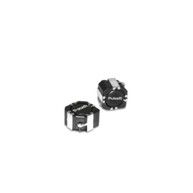
SMT POWER INDUCTORS
Shielded Drum Core - PL93XX Series
Ruggedized
Height: 0.157 inches (4.0mm) Max
Footprint: 0.410 inches x 0.410 inches (10.5mm x 10.5mm) Max
Inductance Range: 0.62µH to 278µH
Current Rating: up to 7.6A
Moisture Sensitivity Level: 1
Part
Numbers
PL9301
PL9302
PL9303
PL9304
PL9305
PL9306
PL9307
PL9308
PL9309
PL9310
PL9311
PL9312
PL9313
PL9314
PL9315
PL9316
PL9317
PL9318
Electrical Specifications @ 25 °C — Operating Temperature - 5 5 °C to +130 °C
Inductance @Irated
DCR (mΩ)
Inductance
Irated 2
Saturation3
(A)
@0ADC (µH) Current (A) @25°C
TYP
MAX
(µH TYP)
0.62
1.2
1.9
2.8
4.0
5.4
6.9
8.0
11
12
19
25
38
55
83
123
178
278
7.60
7.10
5.80
5.20
4.70
3.70
3.50
3.40
3.00
2.80
2.30
2.10
1.65
1.32
1.10
0.88
0.73
0.60
4.2
5.6
8.4
10.2
15.1
20.8
23.7
26.5
36.1
39.5
62
71
113
170
262
400
591
906
5.5
7.3
10.9
13.3
19.6
27.0
30.8
33.2
45.2
49.4
77
89
142
212
328
500
739
1133
*Inductance at 0ADC tolerance on indicated part numbers is ±30%; tolerance is ±20% on all other parts.
Optional Tape & Reel packaging can be ordered by adding a "T" suffix to the part number (i.e. PL9301 becomes PL9301T).
Mechanical
1
www.inrcore.com
0.68±25%
1.3±25%
2.2±25%
3.3±25%
4.7±25%
6.0±25%
7.6±25%
10±20%
12±20%
15±20%
22±20%
27±20%
47±20%
68±20%
100±20%
150±20%
220±20%
330±20%
Heating4
Current (A)
10.00
8.00
6.15
5.80
5.40
4.50
4.00
3.80
3.40
3.10
2.80
2.30
2.10
1.50
1.35
1.15
0.92
0.70
7.60
7.10
5.80
5.20
4.70
3.70
3.50
3.40
3.00
2.80
2.30
2.10
1.65
1.32
1.10
0.88
0.73
0.60
NOTES FROM TABLE: (See back page)
Electrical Schematic
M120.E (07/20)
�SMT POWER INDUCTORS
Shielded Drum Core - PL93XX Series
Ruggedized
Notes from Tables
Percentage of the intitial inductance�
4. The heating current is the DC current, which causes the temperature of
the part to increase
1. Temperature of the component (ambient plus temperature rise) must be
by approximately 40°C. This current is determined by extending the
within specified operating temperature range.
terminals of the component with 30mm length 28 gauge buss wires and
2. The rated current as listed is either the saturation current or the heating
applying the current to the device for 30 minutes. The temperature is
current depending on which value is lower.
measured by placing the thermo-couple between the winding and the
3. The saturation current is the current which causes the inductance to drop
shield.
to 75% of its initial inductance at zero bias. This current is determined
5. In high volt*time applications, additional heating in the component can
by placing the component at room ambient (25°C), and applying a
occur due to core losses in the inductor which may necessitate derating
short duration pulse current (to eliminate self-heating effects) to the
the current in order to limit the temperature rise of the compo-nent. In
component.
order to determine the approximate total loss (or temperature rise) for a
given application, both copper losses and core losses should be taken into
account.
Inductance vs. Current Characteristics
120%
100%
80%
60%
40%
20%
0%
0.0
0.2
0.4
0.6
0.8
1.0
1.2
1.4
1.6
Normalized Isat
2
www.inrcore.com
M120.E (07/20)
�SMT POWER INDUCTORS
Shielded Drum Core - PL93XX Series
Ruggedized
For More Information
Global Sales Representatives and Lo cations:
http://www.inrcore.com
iNRCORE,LLC
311 Sinclair Road Bristol,
PA 19007-6812 U.S.A
Tel: + 1.215.781.6400
Fax: +1.215.7816430
Performance warranty of products offered on this data sheet is limited to the parameters specified. Data is subject to change without notice. Other brand and product names
mentioned herein may be trademarks or registered trademarks of their respective owners. © Copyright, 2020. iNRCORE, LLC. All rights reserved.
3
www.inrcore.com
M120.E (07/20)
�
很抱歉,暂时无法提供与“PL9317”相匹配的价格&库存,您可以联系我们找货
免费人工找货