A-GAGE® High-Resolution MINI-ARRAY®
Instruction Manual
Original Instructions
64118 Rev. D
30 August 2019
© Banner Engineering Corp. All rights reserved
64118
�A-GAGE® High-Resolution MINI-ARRAY®
Contents
1 Product Description
........................................................................................................................................................3
1.1 Emitter and Receiver Models
..........................................................................................................................................................3
1.2 Control Module Models
.................................................................................................................................................................. 4
2 System Overview
............................................................................................................................................................5
2.1 System Features
............................................................................................................................................................................. 5
2.2 Supplied System Software
............................................................................................................................................................. 6
2.3 Typical Applications
........................................................................................................................................................................6
3 Installation Instructions
...................................................................................................................................................8
3.1 Emitter and Receiver Mounting
...................................................................................................................................................... 8
3.2 Control Module Mounting
............................................................................................................................................................... 9
3.3 Wiring
..............................................................................................................................................................................................9
3.3.1 Emitter and Receiver Wiring
..................................................................................................................................................10
3.3.2 Inputs
.....................................................................................................................................................................................10
3.3.3 Outputs
..................................................................................................................................................................................11
3.4 Install the Software
....................................................................................................................................................................... 11
4 Control Module Configuration
...................................................................................................................................... 13
4.1 Communications Setup
................................................................................................................................................................ 13
4.1.1 Ping Routine
.......................................................................................................................................................................... 13
4.1.2 Factory Settings
.................................................................................................................................................................... 14
4.2 System Alignment
.........................................................................................................................................................................14
4.2.1 Push-Button Alignment Routine
............................................................................................................................................14
4.2.2 Software Alignment Routine
..................................................................................................................................................14
4.2.3 Blanking
.................................................................................................................................................................................15
4.3 Programming Control Module Response
..................................................................................................................................... 17
4.3.1 Selected Controller and Serial Communication
.................................................................................................................... 18
4.3.2 Control Mode Selection
.........................................................................................................................................................19
4.3.3 Scanning Method
.................................................................................................................................................................. 19
4.3.4 Scan Analysis Mode Selection
.............................................................................................................................................. 22
.................................................................................................. 22
4.3.5 Analog Output Configuration (Analysis Mode Assignment)
4.3.6 Zero Value
............................................................................................................................................................................. 23
................................................................................................ 23
4.3.7 Discrete Output Configuration (Analysis Mode Assignment)
4.4 Serial Communication with a Host Controller
...............................................................................................................................24
4.4.1 Serial Data Transmission
.......................................................................................................................................................24
4.4.2 Transmission Type
................................................................................................................................................................ 25
4.4.3 Serial Options
........................................................................................................................................................................ 25
4.5 Transfer of PSF to the Control Module
.........................................................................................................................................25
4.5.1 Saving and Recalling PSF Files
.............................................................................................................................................25
4.5.2 PSF Output Analysis
............................................................................................................................................................. 25
4.5.3 Quit and Exit
..........................................................................................................................................................................26
5 System Diagnostics
5.1 Diagnostic Indicators
5.2 Diagnostics Routine
6 Specifications
......................................................................................................................................................27
.................................................................................................................................................................... 27
......................................................................................................................................................................28
............................................................................................................................................................... 29
6.1 Emitter and Receiver Specifications
............................................................................................................................................. 29
6.2 Emitter and Receiver Dimensions
.................................................................................................................................................30
6.3 Emitter/Receiver Mounting Bracket Dimensions
.......................................................................................................................... 31
..................................................................................................................................................... 31
6.4 Control Module Specifications
6.5 Control Module Dimensions
......................................................................................................................................................... 33
7 Accessories
................................................................................................................................................................... 34
7.1 Cordsets
........................................................................................................................................................................................ 34
8 Additional Information
.................................................................................................................................................. 35
8.1 Host Mode Command String
........................................................................................................................................................35
8.2 Serial Data Format and Header String
..........................................................................................................................................35
8.2.1 ASCII Format Data Transmission
.......................................................................................................................................... 35
8.2.2 Binary Format Data Transmission
......................................................................................................................................... 36
8.3 Max Meas Mode Command String
...............................................................................................................................................37
8.4 Glossary
........................................................................................................................................................................................ 38
9 Product Support and Maintenance
.............................................................................................................................. 39
9.1 Contact Us
.....................................................................................................................................................................................39
9.2 Banner Engineering Corp Limited Warranty
................................................................................................................................. 39
�A-GAGE® High-Resolution MINI-ARRAY®
1 Product Description
For Controllers with 2 Analog and 2 Discrete Outputs
•
•
•
•
•
•
•
•
•
•
•
•
Excels at high-speed, precise process monitoring and inspection
applications
A comprehensive combination of scanning modes and outputs:
◦ 10 measurement (Scan Analysis) modes
◦ 3 scanning methods
◦ Beam blanking
◦ Selectable continuous, gated or host-controlled scan initiation
◦ Programmable hysteresis for high and low limits
◦ Serial communication options
Storable scanning programs eliminate reprogramming for repeated
applications
Non-volatile memory stores alignment settings
All models with both Analog and Discrete outputs
Analog output Null setting
Low cost, compared with similar systems
Precision sensors have a 380 mm to 1.8 m (15 in to 6 ft) working range
Wide field of view, easily aligned
Alignment routine equalizes gain of each beam for reliable 2.5 mm (0.10 in)
object detection throughout the array
Host computer or PLC may be used to initiate scans and/or process scan
data
Unique addresses for up to 15 control modules on one EIA-485 Party Line
WARNING:
• Do not use this device for personnel protection
• Using this device for personnel protection could result in serious injury or death.
• This device does not include the self-checking redundant circuitry necessary to allow its use in
personnel safety applications. A device failure or malfunction can cause either an energized (on)
or de-energized (off) output condition.
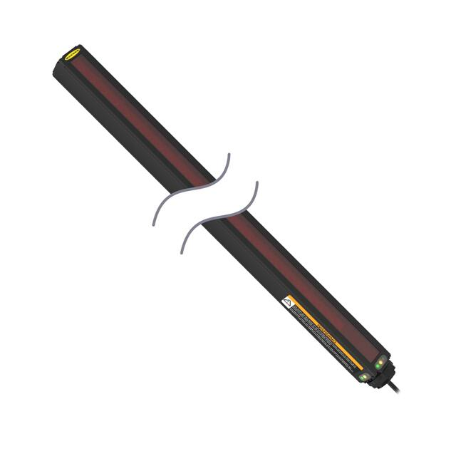
1.1 Emitter and Receiver Models
Emitter Model
Receiver Model
Array Length Y
MAHE6A Emitter
MAHR6A Receiver
163 mm (6.4 in)
64
MAHE13A Emitter
MAHR13A Receiver
325 mm (12.8 in)
128
MAHE19A Emitter
MAHR19A Receiver
488 mm (19.2 in)
192
MAHE26A Emitter
MAHR26A Receiver
650 mm (25.6 in)
256
MAHE32A Emitter
MAHR32A Receiver
813 mm (32.0 in)
320
MAHE38A Emitter
MAHR38A Receiver
975 mm (38.4 in)
384
MAHE45A Emitter
MAHR45A Receiver
1138 mm (44.8 in)
448
MAHE51A Emitter
MAHR51A Receiver
1300 mm (51.2 in)
512
MAHE58A Emitter
MAHR58A Receiver
1463 mm (57.6 in)
576
MAHE64A Emitter
MAHR64A Receiver
1626 mm (64.0 in)
640
MAHE70A Emitter
MAHR70A Receiver
1788 mm (70.4 in)
704
MAHE77A Emitter
MAHR77A Receiver
1951 mm (76.8 in)
768
www.bannerengineering.com - Tel: + 1 888 373 6767
Total Beams
3
�A-GAGE® High-Resolution MINI-ARRAY®
1.2 Control Module Models
Controller Model
Solid-State Discrete Outputs
Analog Outputs
MAHCVP-1
2 PNP
(2) 0 V to 10 V Sourcing
MAHCVN-1
2 NPN
(2) 0 V to 10 V Sourcing
MAHCIP-1
2 PNP
(2) 4 mA to 20 mA Sinking
MAHCIN-1
2 NPN
(2) 4 mA to 20 mA Sinking
4
www.bannerengineering.com - Tel: + 1 888 373 6767
�A-GAGE® High-Resolution MINI-ARRAY®
2 System Overview
The A-GAGE® High-Resolution MINI-ARRAY® measuring light screen is ideal for applications such as on-the-fly product
sizing and profiling, edge-guiding and center-guiding, loop tensioning control, hole detection, parts counting and similar
uses.
A typical A-GAGE High-Resolution MINI-ARRAY system has five components: a high-resolution emitter/receiver pair, each
with quick-disconnect (QD) connectors; one of four compact control modules; and quick-disconnect cables to connect
them. Software is included to interface any PC-compatible computer (running Windows®1 XP, Vista, or 7) with the control
module for system configuration. A host computer or PLC may be used to control and/or receive input from the system.
Sensors are available in twelve array lengths from 163 mm to 1951 mm (6.4 in to 76.8 in), in 163 mm (6.4 in) increments. The
emitter has two columns of infrared LEDs spaced 5 mm (0.2 in) apart. The columns are separated by 7.5 mm (0.3 in) and are
staggered from each other by 2.5 mm (0.1 in). The receiver is configured opposite to the emitter, with the identical length
and beam spacing. This high-resolution sensor pair is capable of detecting a 12.7-mm long by 2.54-mm diameter (0.5 in by
0.1 in diameter) cylindrical rod (held perpendicular to the sensor). The sensors have a wide field of view and are easily
aligned, with a working range of 380 mm to 1.8 m (15 in to 6 ft).
Each of the four versatile microcontroller-based control modules are configured using a PC-compatible computer running
Windows XP, Vista, or 7, and the supplied software, via the built-in RS-232 interface.
2.1 System Features
Built-in features simplify the operation of the A-GAGE High-Resolution MINI-ARRAY system. High-resolution emitters and
receivers, available in twelve lengths, feature two closely spaced columns of beams to provide a precise, high-resolution
light screen for exacting applications. The Alignment routine automatically equalizes the excess gain of each beam for
reliable 2.5-mm (0.10-in) object detection throughout the array and stores this data in non-volatile memory. The Alignment
routine does not need to be performed again unless the sensing application changes, or if the emitter and/or receiver is
moved. Programmable beam blanking accommodates machine components or other fixtures that must remain in or move
through the light screen. Blanking may be set automatically as part of the initial setup, or by using the included
configuration software.
Built-in diagnostic programming and easy-to-see indicators on the sensors and the control module make alignment and
troubleshooting easy. The emitter has a red LED that signals proper operation. The receiver has three bright LEDs: green
signals that the sensors are properly aligned; yellow signals marginal alignment; and red signals misalignment or a blocked
condition. The control module has four status indicators: 3 red LEDs signal discrete output #1 conducting, Alarm output
(discrete output #2) conducting, and gate signal received; a green LED signals that the sensors are properly aligned. A
segmented LED Diagnostics Indicator provides detailed system status using single-digit codes; a period in the indicator
window indicates the presence of blanking. A key to the diagnostics codes is printed on the side of the control module for
simplified troubleshooting.
The A-GAGE High-Resolution MINI-ARRAY system provides a wide selection of sensing and output options, including:
measurement (scan analysis) modes and scanning methods that can determine the target object’s location, overall size,
total height or total width. Scanning may be continuous or controlled by a host process controller or a gate sensor. Up to 15
systems may be networked.
1
Microsoft and Windows are registered trademarks of Microsoft Corporation in the United States and/or other countries.
www.bannerengineering.com - Tel: + 1 888 373 6767
5
�A-GAGE® High-Resolution MINI-ARRAY®
High-Resolution Emitter
7.6 mm (0.30")
High-Resolution Receiver
5.1 mm
(0.20")
2.5 mm
(0.10")
DIN-Rail-Mountable Control Module
MAHCVP-1
HIGH RESOLUTION MINI-ARRAY CONTROLLER
POWER
1
2
3
4
5
F1
BR BU
+
7
8
10
11
12
13
14
15
16
17
18
19
20
TX TX
BK WH
0-10VOLTS
25mA (MAX)
V OUT 1
+V
–
16-30V dc
1A MAX
+ –
+ –
10-30VDC 10-30VDC
GATE
ALIGN
0-10VOLTS
25mA (MAX)
V OUT 2
+V
D OUT 1
150mA MAX
ALARM
150mA MAX
ALIGN
ALIGNMENT
SWITCH
GATE
RCVR
DIAGNOSTICS
INDICATOR
ALARM
EMTR
Alignment Button
9
OUTPUT
Diagnostics Indicator
6
+12V COM DRN T/R T/R
RS-232
2 - TX
3 - RX
5 - COM
POWER
Red
Operational
LED
Green Alignment LED
Red Blocked LED
Yellow Marginal
Alignment LED
Red Discrete Output #1 LED
Red Alarm (Discrete Output #2) LED
Red Gate LED
Green Align LED
RS-232 Port
Figure 1. A-GAGE High-Resolution MINI-ARRAY System Features
2.2 Supplied System Software
The supplied software program, used to configure each system control module, may be run on any PC running Windows®
XP, Vista, or 7. The menu-driven program walks the user through the many scanning and output options. After the desired
options are selected, the user can save the combination of selections in a Parameter Setup File (PSF), and store it in the
control module’s non-volatile memory. Any number of PSFs may be stored in the computer and recalled as needed.
The software also provides alignment and diagnostics routines. An Alignment screen displays the individual status of each
beam in the light screen, as well as the total number of beams in the system, and totals of beams blocked, made, and
blanked. Built-in system diagnostics can be used to assess emitter and receiver hardware errors.
2.3 Typical Applications
Figure 2. Log Profiling for Lumber Optimization
6
www.bannerengineering.com - Tel: + 1 888 373 6767
Figure 3. Box Profiling
�A-GAGE® High-Resolution MINI-ARRAY®
Figure 4. Maintaining Center of Opaque Rolled Goods
Figure 5. Inspection Applications
www.bannerengineering.com - Tel: + 1 888 373 6767
7
�A-GAGE® High-Resolution MINI-ARRAY®
3 Installation Instructions
3.1 Emitter and Receiver Mounting
Banner MINI-ARRAY emitters and receivers are small, lightweight, and easy to handle during mounting. The mounting
brackets (supplied) allow ±30° rotation.
From a common point of reference, make measurements to locate the emitter and receiver in the same plane with their
midpoints directly opposite each other. Mount the emitter and receiver brackets using the vibration isolators and M4 Keps
nuts (all supplied). Standard M4 or #8-32 bolts may be substituted (and the vibration isolators eliminated) in situations
where the emitter and receiver are not subjected to shock or vibration forces. While the internal circuits of the emitter and
receiver are able to withstand heavy impulse forces, the vibration isolators dampen impulse forces and prevent possible
damage due to resonant vibration of the emitter or receiver assembly.
M4 x 10 mm
Slotted Hex Head
with Compression
Washer (2)
Mounting
Surface
Mounting
Bracket
M4 Keps
Nut (8)
Emitter or
receiver
Anti-Vibration
Mount (4)
Studs: M4 x 0.7
9.5 mm (0.38") long
Mounting
Bracket
Washer
Nut
Figure 6. A-GAGE High-Resolution MINI-ARRAY emitter and receiver mounting hardware
1. Mount the emitter and receiver in their mounting brackets; see Figure 6 (p. 8).
2. Position the red lenses of the two units directly facing each other. The connector ends of both sensors must point in
the same direction.
3. Measure from one or more reference planes (for example, the floor) to the same points on the emitter and receiver to
verify their mechanical alignment. If the sensors are positioned exactly vertical or exactly horizontal, a carpenter’s
level may be useful for checking alignment. Extending a straight-edge or a string between the sensors may help with
positioning.
4. Also check by eye for line-of-sight alignment.
8
www.bannerengineering.com - Tel: + 1 888 373 6767
�A-GAGE® High-Resolution MINI-ARRAY®
5. Make any necessary final mechanical adjustments, and hand-tighten the bracket hardware.
6. See System Diagnostics (p. 27) for information on alignment indicators and Control Module Configuration (p. 13)
for information on the use of the alignment software which is supplied with the controller.
3.2 Control Module Mounting
Install the controller inside an enclosure with a NEMA (or IEC) rating suitable for the operating environment. Mounting
dimensions for the controller are shown in Control Module Dimensions (p. 33). The controller is supplied with M3.5
hardware for direct mounting to a surface, or it can be mounted onto standard 35 mm DIN rail.
3.3 Wiring
Refer to the following figures for the appropriate wiring information.
POWER
5
6
–
BLUE
+
BROWN
F1
16-30V dc
1 A max
7
8
9
10
11
12
13
14
15
16
17
18
25 mA
max
+
–
10-30V dc
GATE
SIGNAL
WHITE
4
BLACK
3
DRAIN (BARE)
2
1
EMITTER and
RECEIVER CABLES
0-10V
ANALOG
OUTPUT #1
DISCRETE
OUTPUT#1
150 mA
max
19
TX TX
RS-485
+
–
10-30V dc
ALIGN
DISCRETE
OUTPUT#2 (ALARM)
25 mA
max
0-10V
ANALOG
OUTPUT #2
+30V dc max
20
150 mA
max
+30V dc max
Figure 7. MAHCVN-1 Wiring
5
–
16-30V dc
1 A max
BLUE
+
BROWN
F1
6
7
8
9
10
11
12
13
14
15
16
17
25 mA
max
+
–
10-30V dc
GATE
SIGNAL
WHITE
4
BLACK
3
DRAIN (BARE)
POWER
1
2
0-10V
ANALOG
OUTPUT #1
DISCRETE
OUTPUT#1
EMITTER and
RECEIVER CABLES
18
19
TX TX
RS-485
+
–
10-30V dc
ALIGN
DISCRETE
OUTPUT#2 (ALARM)
25 mA
max
150 mA
max
0-10V
ANALOG
OUTPUT #2
150 mA
max
20
5
6
+
–
16-30V dc
1 A max
BROWN
F1
7
EMITTER and
RECEIVER CABLES
8
9
10
DISCRETE
OUTPUT#1
150 mA
max
+30V dc
11
12
13
+
–
10-30V dc
GATE
SIGNAL
WHITE
4
BLACK
3
DRAIN (BARE)
POWER
1
2
BLUE
Figure 8. MAHCVP-1 Wiring
14
15
16
17
19
20
TX TX
RS-485
+
–
10-30V dc
ALIGN
Load
18
Load
4-20 mA
ANALOG
OUTPUT#1
4-20 mA
ANALOG
OUTPUT#2
+16-30V
+16-30V
DISCRETE
OUTPUT#2 (ALARM)
150 mA
max
+30V dc max
Figure 9. MAHCIN-1 Wiring
www.bannerengineering.com - Tel: + 1 888 373 6767
9
�5
6
+
–
16-30V dc
1 A max
BROWN
F1
7
EMITTER and
RECEIVER CABLES
8
9
10
11
DISCRETE
OUTPUT#1
150 mA
max
12
13
+
–
10-30V dc
GATE
SIGNAL
WHITE
4
BLACK
3
DRAIN (BARE)
POWER
1
2
BLUE
A-GAGE® High-Resolution MINI-ARRAY®
4-20 mA
ANALOG
OUTPUT #1
14
15
+
–
16
17
18
19
20
TX TX
RS-485
10-30V dc
ALIGN
DISCRETE
OUTPUT#2 (ALARM)
4-20 mA
ANALOG
OUTPUT #2
Load
150 mA
max
Load
+16 – 30V dc
+16 – 30V dc
Figure 10. MAHCIP-1 Wiring
3.3.1 Emitter and Receiver Wiring
Connect emitters and receivers together in parallel to terminals #4 through #8 of the control module (identical for all control
module models). See the figures in Wiring (p. 9) for wire color information.
Trim braided shield flush
with cable
Trim foil shield flush
with cable
Uninsulated
drain wire
Note: The “drain wire” is the
uninsulated stranded wire which runs
between the braided shield and the
foil shield. The foil shield and the
braided shield should be removed at
the point where the wires exit the
cable.
Figure 11. Emitter and Receiver Cable Preparation
3.3.2 Inputs
System Power: Connect a source of 16 V dc to 30 V dc, rated at 1 amp or greater, to control module terminals #1 (+) and #2
(-). Connect a good earth ground to terminal #3 to provide electrical and RF noise immunity to the System.
Note: Remove power before making other connections to the controller.
Gate Signal: A source of 10 V dc to 30 V dc switched to terminals #12(+) and #13(-) provides a gating input (if required). The
gating voltage typically is switched by the open-collector output transistor of a dc sensing device. The gate signal controls
scanning when one of four Gate options is selected in the Control Mode Selection menu of the PSF configuration routine
(see Control Mode Selection (p. 19)) .
Align: A source of 10 V dc to 30 V dc switched to terminals #14(+) and #15(-) provides a remote means of running the
automatic alignment and blanking routines. The switch sequence is identical to the procedure described in Push-Button
Alignment Routine (p. 14) for the Alignment switch on the front of the control module.
10
www.bannerengineering.com - Tel: + 1 888 373 6767
�A-GAGE® High-Resolution MINI-ARRAY®
3.3.3 Outputs
Control Module
Analog Outputs (Terminals #10 and 16)
Discrete Outputs2 (Terminals #9 and
20)
0 V to 10 V Sourcing
NPN open-collector
MAHCVN-1
Figure 7 (p. 9)
15 mA maximum
30 V dc maximum
150 mA maximum
MAHCVP-1
0 V to 10 V Sourcing
PNP open-collector
15 mA maximum
30 V dc maximum
4 mA to 20 mA
NPN open-collector
Sinking
30 V dc maximum
16 V dc to 30 V dc
150 mA maximum
4 mA to 20 mA
PNP open-collector
Sinking
30 V dc maximum
16 V dc to 30 V dc
150 mA maximum
Figure 8 (p. 9)
MAHCIN-1
Figure 9 (p. 9)
MAHCIP-1
Figure 10 (p. 10)
Serial Communication
RS-232: All A-GAGE High-Resolution MINI-ARRAY Systems may communicate with a host computer or controller via
RS-232 or RS-485 serial protocol. See Section 5.3.1 for selectable communications parameters. Prepare an RS-232 cable
using a male DB-9 connector with connections as shown.
Note: DO NOT use a “null modem” RS-232 cable
RS-232
5
3 2
2 - TX
3 - RX
5 - COM
DB-9 Pin #
Function
2
Transmit (TX)
3
Receive (RX)
5
Ground (GND)
Figure 12. DB-9 connections between the control module and the PC
RS-485: RS-485 serial port is located at terminals #18 (TX) and #19 (TX).
3.4 Install the Software
The Parameter Setup Software CD includes an installation program that quickly and easily loads the MINI-ARRAY
configuration program into the computer. The MINI-ARRAY configuration program requires approximately 50 MB of hard
disk space. Install as follows:
1. Use the Parameter Setup Software CD included with the controller, or download from www.bannerengineering.com
as required.
2
Discrete Output #2 is labeled Alarm on the control module.
www.bannerengineering.com - Tel: + 1 888 373 6767
11
�A-GAGE® High-Resolution MINI-ARRAY®
2. Insert the Software CD into the CD drive.
•
If the program does not auto-start, browse to your CD drive, click Setup.exe, then select START, then select
RUN. The Welcome dialog box displays. Select Next, and follow the prompts in the dialog boxes as they appear.
• If the program does auto-start, the Welcome dialog box appears. Select Next, and follow the prompts in the
dialog boxes as they appear.
3. The installation program decompresses the files. A status dialog box monitors the progress of the installation.
4. An Installation Completed dialog box appears. Select OK.
5. Reboot your computer for the changes to take effect.
After the software is installed, a MINI-ARRAY shortcut icon is placed on your desktop. Double-click the MINIARRAY icon to launch the program, then follow the configuration instructions.
12
www.bannerengineering.com - Tel: + 1 888 373 6767
�A-GAGE® High-Resolution MINI-ARRAY®
4 Control Module Configuration
Configure the A-GAGE High-Resolution MINI-ARRAY control module using a Windows® menu-style routine; the
configuration routine requires the Banner-supplied HRMA software and a PC-compatible computer (running Windows® XP,
Vista, or 7). Make a serial data connection between the computer and the DB9 connector on the control module.
4.1 Communications Setup
1. After installing the software, attach the serial communication cable between the control module and the PC.
Note: If an RS-232 interface is used, only one control module is allowed on the line at any one
time.
The minimum connections to the control module’s DB-9 connector are shown in Figure 12 (p. 11).
2. Launch the High-Resolution MINI-ARRAY program.
3. Configure the serial communications port of the PC.
a) Select Options > Serial Port from the High-Resolution MINI-ARRAY main menu.
The program supports serial communication via the COM1-COM20.port of the computer.
b) Highlight the desired serial port to select it.
c) Select Save Settings on Exit to store the serial port selection, if it is not already ON.
Parity is selected here also: Even, Odd or None.
4.1.1 Ping Routine
Perform the Ping routine during system configuration, and before any Diagnostic, Alignment, or Edit routine. The routine
polls all control modules on the communications line (one, in the case of the standard RS-232 line, or up to 15 modules, on
an RS-485 circuit). It then is used to select an individual control module for configuration or alignment.
1. If needed, apply power to the system control module and allow the system to complete its power-up routine.
2. Press F5 or access the MINI-ARRAY menu.
3. Select Ping to perform the Ping routine.
All connected control modules identify themselves with an ID value and baud rate; the routine takes approximately
15 to 20 seconds. After the Ping is performed, all valid control module ID values display in a chart on the screen,
under their appropriate baud rates. Control modules are identified in the chart as X.
Figure 13. Screen showing the result of a completed Ping routine
4. Point to a valid ID and click to select a control module.
System Diagnostics, Alignment, or Edit routines may now be performed for the selected control module.
www.bannerengineering.com - Tel: + 1 888 373 6767
13
�A-GAGE® High-Resolution MINI-ARRAY®
4.1.2 Factory Settings
Of the 15 available control module ID values (A through O), the factory software setting is A. Selectable communication
baud rates are 9600, 19200, and 38400; the factory setting is 9600. See Selected Controller and Serial Communication (p.
18) for information on changing these settings.
4.2 System Alignment
The emitter/receiver pairs have a wide field of view and are easy to align. The recommended distance between the emitter
and receiver ranges from 380 mm to 1829 mm (15 in to 72 in). Shorter sensor separation can be achieved; consult Banner
Engineering for details.
Perform the Alignment process at System installation and repeat it every time one or both of the sensors is moved.
Alignment of the System can be specified automatically using either the Alignment routine of the configuration software or
the Alignment switch on the control module’s front panel.
The System also may be aligned remotely, using pins 14 and 15 on the terminal block. Apply 10 V dc to 30 V dc power to
the pins to approximate the push-button procedure. For example, apply input signal for 3 seconds to access Alignment
mode.
1. Make sure the sensors have been wired as shown in Wiring (p. 9).
2. Apply power to the control module via terminals #1 and #2 (16 V dc to 30 V dc).
The Diagnostics Indicator shows the sensors going though a power-up test: first the receiver, then the emitter. After
the sensors have been tested and the System is ready for service, the Diagnostics Indicator shows — or —.; see
figure.
ALIGNMENT
SWITCH
150mA MAX
ALIGN
RCVR
DIAGNOSTICS
INDICATOR
GATE
EMTR
ALARM
ALIGN
GATE
ALIGNMENT
SWITCH
ALARM
RCVR
DIAGNOSTICS
INDICATOR
OUTPUT
EMTR
With Blanking ON
150mA MAX
OUTPUT
With Blanking OFF
R
R
Denotes
Blanking
Figure 14. Diagnostics Indicator Showing a Clear Condition
4.2.1 Push-Button Alignment Routine
Re-align the System at installation or whenever the emitter and/or receiver is moved.
1. Press the Alignment switch on the control module front panel for 3 seconds.
The letter A displays on the Diagnostics Indicator; the System is learning a clear condition.
2. Rotate the sensors as required (but do not change the distance between them).
When the green Alignment LED is displayed on the control module and receiver, the sensors are adequately aligned.
3. To leave Alignment mode, press the Alignment switch for 3 seconds.
During the alignment procedure, the System polls each receiver channel to measure excess gain and performs a coarse
gain adjustment. When the System exits the alignment procedure, each channel’s signal strength is stored in non-volatile
memory. The System is now ready for operation and does not require re-alignment unless the emitter or receiver is moved.
4.2.2 Software Alignment Routine
The green LED indicator on the receiver and also on the control module continuously displays Alignment status. When all
unblanked beams are clear, the green Alignment indicators are ON. To better understand blocked, clear, and blanked
beams, launch the Alignment routine (press F8 or select Alignment under the MINI-ARRAY menu). The screen shows the
state of all of the beam channels, grouped into sets of 16.
Key information provided on the Alignment screen is the sensor size, plus the number of beams blocked, made, and
blanked. The sensor size is given the title of Total; this refers to the total number of beam channels in the array. The number
of beams blocked is a running total of blocked beams, excluding any blanked beams. The Made value is a count of
unblocked beams. The Blanked value is a count of the number of beam channels that are blanked (channels that are
ignored for measurement mode applications).
14
www.bannerengineering.com - Tel: + 1 888 373 6767
�A-GAGE® High-Resolution MINI-ARRAY®
The Alignment screen provides the following functions: Start, Stop, Step, Clear Blanking Fields, Restore Control module
Settings, Auto Blanking, Abort Auto Blanking, Save to File, Read From File, Cancel, OK, and Edit. To access any of these
sub-routines, first click Stop, then the selected option.
Start causes the control module to continuously scan and report All Channel Data. This data is used to update the state of
each beam channel.
Stop causes the control module to stop scanning.
Step produces one scan and then stops until another command is issued.
Clear Blanking Fields is a quick way to remove blanking specifications.
Restore Control Module Settings recalls the blanking specifications in effect prior to Alignment/Blanking being entered.
Auto Blanking is used to scan and determine which beams are blocked; blocked beams automatically become blanked
beams. The Auto Blanking values can then be Accepted or Aborted.
Edit is used to control the blanking specifications of any channel manually. This is useful for adding any number of blanked
beam channels above and/or below a blanked object to allow for vibration or other movement of the object to be ignored.
Blanking specifications can be saved and read from a computer file using Save To File and Read From File commands.
Figure 15. Alignment screen
4.2.3 Blanking
If a machine fixture or other equipment will continuously block one or more beams, the affected beam channels may be
blanked. The Blanking option causes the control module to ignore the status of blanked beams for measurement mode
calculations. For example, if a machine fixture blocks one or more beams during System operation, the output data will be
incorrect; if beams blocked by the fixture are blanked, the output data will be correct. Blanking may be configured using the
push-button Alignment switch on the control module, or by using the System software and a computer.
Push-Button Blanking Setup Routine
To specify blanking using the control module’s Alignment switch, position the object or part to be ignored in the path of the
beams before beginning the Alignment routine.
1. Press the Alignment switch for 3 seconds.
The Diagnostics Indicator shows the letter A.
2. Press the Alignment switch momentarily (about 0.5 seconds maximum).
The Diagnostics Indicator shows the letter b to indicate it is ready to learn the blanking pattern.
3. Press the Alignment switch momentarily (about 0.5 seconds maximum) to set the blanking fields.
Both the control module and the receiver indicate a clear condition (green Align indicator ON) and the Diagnostics
Indicator shows A. (the period following the A indicates that blanking is in use). The beams blocked during the
routine are now blanked.
4. To return to Run mode, again press the Alignment switch for 3 seconds.
When the System is ready for operation and configured for beams to be blanked, the period on the Diagnostics
Indicator remains lit, showing —..
www.bannerengineering.com - Tel: + 1 888 373 6767
15
�A-GAGE® High-Resolution MINI-ARRAY®
System Software Blanking Setup Routine
1. Position the object to be blanked in the path of the beams (this can be done at any time before beginning the
blanking routine).
2. Perform the Ping routine to select the proper control module.
3. Press F8 or select the Alignment option from the MINI-ARRAY menu.
4. From the screen menu, select Stop.
The Diagnostics Indicator on the control module shows the letter A.
5. Select Auto Blanking.
The Diagnostics Indicator shows the letter b.
6. Select Accept Auto Blanking.
Both the control module and the receiver indicate a clear condition (green Align indicator ON) and the Diagnostics
Indicator shows A. (the period following the A indicates that blanking is in use). The beams blocked during the
routine are now blanked and appear as the letter B on the grid instead of 0.
Figure 16. Alignment screen, showing beams #1-11 blocked
Figure 17. Alignment screen, showing beams #1-11 blanked
7. To blank additional beams, use Edit to manually set additional blanking (see Scanning Mode Limitations for Blanking
(p. 16)).
8. To leave Alignment mode, click OK.
When the System is ready for operation and configured for beams to be blanked, the period on the Diagnostics
Indicator will remain lit, showing —..
Scanning Mode Limitations for Blanking
All blanking features are available with Continuous Scan mode. For single-and double-edge scan, blanking is limited to four
blanking fields. Other blanking features are ignored.
To accommodate parts or components that will move through the array, blanking may be manually adjusted for one or more
individual beam channels.
1. After using the system software to specify blanking, select Edit from the Alignment screen.
The Diagnostics Indicator continues to show the letter b and a grid displays on the computer screen. The beams are
numbered from the sensors’ cabled ends, with the beam closest to the cable being beam #1.
16
www.bannerengineering.com - Tel: + 1 888 373 6767
�A-GAGE® High-Resolution MINI-ARRAY®
Figure 18. Edit channel blank state screen, showing beam #22 and beams #35-42 blanked; beams #65-80 are highlighted, ready to be selected
for blanking
2. To set the blanking fields, click each grid box representing a beam you wish to blank.
3. Clicking again on a blanked beam channel removes the blanking specification.
4. To select or clear the blanking specification for several rows of channels, place the cursor directly to the left of the
row to be selected and click the mouse. The rows highlight.
5. Select Blank Selected (to accept the blanking status) or Clear Selected (to reject the blanking status) option.
6. To leave Alignment mode, click OK.
Both the control module and the receiver indicate a clear condition (green Align indicator ON) and the Diagnostics
Indicator shows A.. When the system is ready for operation and configured for beams to be blanked, the period on
the Diagnostics Indicator remains lit, showing —..
4.3 Programming Control Module Response
Use the Parameter Setup File (PSF) Configuration routine to configure the control module for a specific application. After
performing the Ping routine to select a control module, access the PSF Configuration screen by selecting Edit PSF (F4) from
the MINI-ARRAY menu. The Edit PSF process may also be performed with no control module selected, to configure and
save a PSF for multiple control modules. In such a case, some fields on the PSF Configuration screen will not be
accessible.
The process of configuring the control module involves selecting among options for each of the parameters listed in this
section, including serial communication, control mode, scanning method, scan analysis mode, serial transmission, and
analog/discrete outputs. The resulting combination of options causes the control module to react as required for the
application, to changes in the light screen.
The configuration process produces a Parameter Setup File (PSF). PSF files may be saved and retrieved as computer files
via File Save PSF and File Retrieve PSF (see Saving and Recalling PSF Files (p. 25)) . After it is configured, a PSF may be
sent to the control module via the Send PSF command. The PSF currently loaded into the control module may be displayed
by using the Upload PSF command.
www.bannerengineering.com - Tel: + 1 888 373 6767
17
�A-GAGE® High-Resolution MINI-ARRAY®
Selected Controller
Identifies the specific
control module being
configured.
Control Mode Selection
Analysis (Measurement)
Mode Selection
Choose the measurement
option that best tells you
the size and/or position
of objects as they
relate to the array.
Serial Communication
Changes the
identification
and baud rate of the
controller being configured.
Continuous Mode: The control
module constantly polls
the array for status.
Host Mode: The control module
polls the array for status when
prompted by a host controller.
Gate Mode: The control module
polls the array for status when
prompted by an input from a
Gate sensor.
Serial Transmission
Specifies the type of data transmitted
from the control module to its host
after each scan.
Measurement Mode Result: Data
transmitted will reflect the Analysis
Mode selections.
All Mode: Transmits all data.
Max. Meas. Mode: Sends only the largest
measurement in each measuring event,
to decrease transmission size and speed
response. Choose to send when the
array is clear or send at the host’s
request.
Transmission Type: ASCII or Binary,
defines the format in which the data
will be sent.
Serial Options: Suppress Clear Data
or Suppress Header to decrease
transmission size and speed response.
Scanning Method
Straight scan polls each beam
sequentially to determine the
target object’s overall size. This is
the most accurate and precise
measurement, but also the most
time-consuming.
Single Edge scan requires the
target object to block beam 1
(closest to the sensors’ cabled
ends), then conducts a time-saving
binary search to “hunt” for the
target’s overall height (one
variable edge).
Double Edge scan conducts a
time-saving search of the entire
array to “hunt” for the target’s
overall width (two variable edges)
Zero Value
Zero Value is used to specify the
analog output when the
measurement mode value is
zero. The user can specify a
value of LAST, NULL, or SPAN.
LAST: Output holds the last non-zero value before the
light screen became clear.
Scan #: (1-9) Analog outputs are
updated with an average value of the
data received during the selected
number of scans; discrete outputs
respond only if the received data is
identical for all of the selected number
of consecutive scans.
NULL: Provides the minimum value.
SPAN: Provides the maximum value.
Trigger/Trigger Channel Number
Analog and Discrete
Output Assignment
Assigns an analysis
(measurement) mode
to each output.
May be used to trigger (or gate) the scan sequence of another
A-GAGE High-Resolution MINI-ARRAY controller; in straight
scanning mode, it defines when during each scan discrete Output
#2 will change state.
Set Point and
Hysteresis Selection
Assigns the set point to
determine where within
the array the output(s)
will respond and
hysteresis values to
smooth output response.
Alarm: Causes the control module to
turn on discrete Output #2 whenever
the System detects a sensing error or
if the optical signal becomes marginal.
Figure 19. Use the PSF Configuration Screen to Program Each Control Module Individually
4.3.1 Selected Controller and Serial Communication
The Selected Controller box displays information about the control module being configured. Two of these settings may be
changed in the Serial Communication box. The settings selected and displayed in these boxes are those used to identify
the control module during the Ping routine.
Controller ID (assigned a letter, A through O) is used to identify each individual control module when multiple discreteoutput control modules (up to 15) are connected on one EIA-485 party line.
Note: Analog output control modules do not offer RS-485 communication; choose any ID letter (A
through O) when programming an analog-output control module.
18
www.bannerengineering.com - Tel: + 1 888 373 6767
�A-GAGE® High-Resolution MINI-ARRAY®
Baud Rate is the data communication rate between the control module and the computer used for configuration and also
the process controller. Choose from three values: 9600, 19200, and 38400.
Parity: Select Odd, Even, or None. All controllers on one EIA-485 party line should have the same parity settings.
4.3.2 Control Mode Selection
The control mode determines the method used to control scanning of the light screen array. Choose from three main
control modes:
• Continuous Scan Mode
• Serial Host Command Mode
• Gate Mode, which has four options
In Continuous Scan mode, the control module begins a new scan as soon as it updates the outputs from the previous scan.
This is the fastest scan control method; it is used in most analog output applications and whenever continuous updating of
the outputs is acceptable.
Host mode allows the control module to communicate with a host computer or control module via RS-232 (all models) or
RS-485 (discrete-output models only) serial protocol. The host directs the control module to scan on demand and receives
the output data from the control module in binary or ASCII form. Baud rates of 9600, 19200, and 38400 are selectable in the
Serial communications menu. See Additional Information (p. 35) for more information on Host mode data format.
Gate mode activates an optically isolated external Gate input between terminals 12 (+) and 13 (-) of the control module. The
Gate input has impedance of 7.5 kΩ and accepts a 10 V dc to 30 V dc signal. A dc device such as a photoelectric sensor or
optical encoder typically supplies the Gate input. Gate input signals must be greater than 150 microseconds in duration; the
time between successive Gate inputs must be greater than the minimum scan time for the light screen array (see Scanning
Method (p. 19) for scan time information).
Gate mode has four options:
• Gate ON: the control module will scan as long as the gate is active.
• Gate OFF: the control module will scan whenever the gate is not active.
• Gate ON/OFF: the control module will scan once for each gate transition from ON to OFF.
• Gate OFF/ON: the control module will scan once for each gate transition from OFF to ON.
4.3.3 Scanning Method
The control module may be configured for one of three scanning methods:
• Straight Scan
• Single-Edge Scan
• Double-Edge Scan
Straight scan is the default mode in which all beams are scanned in sequence from the bottom end (cable end) to the top
end of the array. This scanning method requires the longest scan times and provides the smallest object detection size (2.5
mm, 0.1 in diameter).
Single-Edge scan is used to measure the height of a single object. A good application for this scanning method is box
height measurement. For Single-Edge scan, the system always activates the first beam channel (nearest the cable end, or
bottom). If the first beam is blocked, the sensor performs a binary search to hunt for the last beam blocked. Single-Edge
scan works as follows:
1. The receiver scans only the bottom beam until that beam is blocked.
2. When the bottom beam is blocked, the sensor looks to see whether the middle beam is blocked or made
(unblocked).
3. If the middle beam is made (unblocked), the sensor checks the bottom quarter beam; if the middle beam is blocked,
the sensor checks the top quarter beam. This is called a binary search.
4. This routine continues to narrow the field until the edge is found.
www.bannerengineering.com - Tel: + 1 888 373 6767
19
�A-GAGE® High-Resolution MINI-ARRAY®
Step #1
High-Resolution
Emitter
Step #2
Beam #1 of 64
Blocked
MAHCN-1
Control Module
Step #3
Beam #32
Blocked
Beam #48
Clear
High-Resolution
Receiver
N-1
MAHC
R
ROLLE
CONT
RRAY
No.
—
1
2
3
4
N MINI-A
LUTIO 8 9
DIAG
Error
Type
System
OK
Align
/ blank
Output
Short
E/
R Mismatc
Receive
h
r Error
NOS
TICS
Error
4
5
6
7
8
RESO
HIGH
No.
POWER 2
1
Error
Type
Emitter
Error
Serial
Comm
EEPROM
CPU
Null
3
+
10
11
12
+
14
15
+
16
–
17
18
20
19
NC
TX
TX
RS-485
ALARM
10-30Vdc
ALIGN
–
MAX
30V(MAX)
150mA
STICS
OR
DIAGNO
INDICAT
EMTR
ENT
ALIGNM
SWITCH
3
4
5
6
7
8
9
TX
2RX
3COM
5-
2
RS-23
RCVR
–
dc
16-30V
MAX
1A
Error
/ Span
POWER 2
1
13
10-30Vdc
GATE
NC
7
6
T/R
5
T/R
WH
4
DRN
OUTPUT#1
BK
COM
NC +12V BU
5 Wires
BR
30V
MAX
150mA
F1
OUTPUT
ALARM
GATE
ALIGN
Error
10
11
12
13
14
15
16
17
18
19
20
Step #4
Step #5
Beam #40
Blocked
Step #6
Beam #44
Clear
Step #7
Beam #42
Blocked
Beam #43
Blocked
Figure 20. Finding an Edge Using a Binary Search
Note that the receiver always checks the bottom beam first, and only if that beam is blocked does the binary search
continue. Therefore, Single-Edge scan will not work in instances where an item that does not block the first beam is to be
measured. Single-Edge scan is also ineffective if the object does not present a continuous blocked pattern. In other words,
Single-Edge scan is used for single, solid objects that block the first beam.
Double-Edge scan is used to detect two edges of a single object, for example, box width measurements. Double-Edge
Scan requires the selection of a step size: 2, 4, 8, 16 or 32 beams. The sensor uses the steps to skip over beams. DoubleEdge scan works as follows:
1. The sensor activates beam #1 (the beam closest to the sensor cable end).
2. The sensor activates the next beam, determined by the step size. For example, if the step size is 2, beam #3 is next;
if the step size is 8, beam #9 is next.
3. As long as the activated beam is unblocked (or made), the sensor continues the stepping routine until a blocked
beam is found.
4. When a blocked beam is found, a binary search is conducted to find the object’s bottom edge.
5. When the bottom edge is found, the sensor begins stepping again through the array until the sensor finds the next
unblocked beam.
6. A binary search is again performed to find the second edge.
Note that this scanning method sacrifices object detection size for speed. Similar to Single-Edge scan, Double-Edge scan
has some restrictions: the object should provide a solid obstruction; the size of the object will determine the maximum step
size.
Table 1: The Effect of Step Size on Minimum Object Detection Size
Number of Beams
Step Size
Minimum Object
Detection Size
2
4
8
16
32
5 mm (0.2 in)
10 mm (0.4 in)
20 mm (0.8 in)
40 mm (1.6 in)
80 mm (3.2 in)
Sensor response time is a function of sensor length and scanning method. Typical scan times are shown in the following
table.
Table 2: The Effect of Sensor Length and Scanning Method on Scan Time (Typical)
Maximum Scan Time (in milliseconds)
Array Length
163 mm (6.4 in)
20
Double-Edge Scan
Straight Scan
Single-Edge
Scan
Step 2 Beams
Step 4 Beams
Step 8 Beams
Step 16 Beams
Step 32 Beams
5.8
1.8
4.8
3.4
2.7
2.5
2.6
www.bannerengineering.com - Tel: + 1 888 373 6767
�A-GAGE® High-Resolution MINI-ARRAY®
Maximum Scan Time (in milliseconds)
Double-Edge Scan
Straight Scan
Single-Edge
Scan
Step 2 Beams
Step 4 Beams
Step 8 Beams
Step 16 Beams
Step 32 Beams
325 mm (12.8 in)
10.6
1.9
8.1
5.1
3.6
3.0
2.7
488 mm (19.2 in)
15.0
2.1
11.5
6.8
4.5
3.4
3.0
650 mm (25.6 in)
20.1
2.1
14.9
8.5
5.3
3.9
3.2
812 mm (32.0 in)
24.9
2.1
18.3
10.1
6.1
4.2
3.5
975 mm (38.4 in)
30.0
2.1
21.7
11.8
7.0
4.7
3.6
1138 mm (44.8 in)
34.5
2.1
25.0
13.5
7.9
5.1
3.8
1300 mm (51.2 in)
39.3
2.1
28.4
15.2
8.7
5.5
4.1
1463 mm (57.6 in)
44.0
2.2
31.8
16.9
9.5
5.9
4.3
1626 mm (64.0 in)
48.0
2.3
35.1
18.6
10.4
6.4
4.5
1788 mm (70.4 in)
53.6
2.3
38.5
20.3
11.2
6.8
4.7
1951 mm (76.8 in)
58.4
2.3
41.9
21.9
12.1
7.2
4.9
Array Length
Note: Scan times are exclusive of serial communication transmission times.
www.bannerengineering.com - Tel: + 1 888 373 6767
21
�A-GAGE® High-Resolution MINI-ARRAY®
4.3.4 Scan Analysis Mode Selection
The control module may be programmed, if desired, for any
one or two of seven Scan Analysis (measurement) Modes.
Each selected mode may be assigned individually to an
output (see section Analog Output Configuration (Analysis
Mode Assignment) (p. 22) or Zero Value (p. 23)). The
beams in the array are numbered in sequence, with beam
#1 located at the cabled end of the emitter and the receiver.
Beam Location Modes
• First Beam Blocked (FBB): The control module
identifies the location of the First Beam Blocked.
• First Beam Made (FBM): The control module
identifies the location of the First Beam Made
(unblocked).
• Last Beam Blocked (LBB): The control module
identifies the location of the Last Beam Blocked.
• Last Beam Made (LBM): The control module
identifies the location of the Last Beam Made
(unblocked).
• Middle Beam Blocked (MBB): The control module
identifies the location of the Middle Beam Blocked,
midway between the first and last beams blocked.
Beam Total Modes
• Total Beams Blocked (TBB): The control module
totals the number of blocked beams.
• Total Beams Made (TBM): The control module totals
the number of made (unblocked) beams.
• Contiguous Beams Blocked (CBB): The control
module identifies the largest number of
consecutively blocked beams.
• Contiguous Beams Made (CBM): The control
module identifies the largest number of
consecutively made beams.
• Transitions (TRN): The control module counts
changes from blocked to clear and clear to blocked.
For instance, if beams 6-34 are blocked, then there
is a clear-to-blocked transition from beam 5 to beam
6, and a blocked-to-clear transition from beam 34 to
beam 35. Transition mode can be used to count
objects within the array.
Receiver
Last Beam Made (LBM)
First Beam Made (FBM)
Emitter
48
40
32
24
16
In Last Beam Made mode,
last beam is #37 of 48
In First Beam Made mode,
first beam is #26 of 48
8
Receiver
Last Beam Blocked (LBB)
First Beam Blocked (FBB)
Emitter
48
40
In Last Beam Blocked mode,
last beam is #43 of 48
32
24
16
In First Beam Blocked mode,
first beam is #15 of 48
8
Receiver
Total Beams Made (TBM)
Total Beams Blocked (TBB)
Emitter
48
40
In Total Beams Made mode,
34 of 48 possible beams are
made
32
24
16
8
In Total Beams Blocked mode,
14 of 48 possible beams are
blocked
Figure 21. Examples of MINI-ARRAY Scan Analysis Modes
The Analysis Mode(s) programmed may be assigned to any
one of the available outputs. Each output can be set for
MEAS1, MEAS2, MEAS1 Inverted, or MEAS2 Inverted.
4.3.5 Analog Output Configuration (Analysis Mode Assignment)
Analog outputs #1 and #2 may each be assigned to one of the analysis modes. When the selected Scan Analysis Mode
involves first or last beam blocked or made (unblocked), the assigned output will vary in proportion to the beam number
identified during a scan. When the Scan Analysis Mode involves total beams blocked or made, that assigned output will
vary in proportion to the total beams counted during a scan.
Note that the menus used for assignment of the Scan Analysis Modes to the analog outputs include two Inverted
selections. When either MEAS1 Inverted or MEAS2 Inverted is selected, that analog output will decrease as the
measurement mode value increases. An inverted output is at full scale (Span value) when the scan analysis value is zero;
and at maximum scan analysis value, the output is at the Null value.
The Null/Span Configuration screen , may be used to adjust the zero and full scale reading for either analog output. To
display the Null/Span Configuration screen, click on the Null/Span button at the bottom of the PSF Configuration screen.
Each output is independent and must be adjusted separately. Adjust the Null and Span values either by moving the slide
bars, or by entering a new value on the keyboard.
Note: When in the Null/Span screen, the controller has a diagnostic code of 8.
22
www.bannerengineering.com - Tel: + 1 888 373 6767
�A-GAGE® High-Resolution MINI-ARRAY®
Figure 22. Null/Span Configuration screen
To Measure:
Analog Voltage Output: Connect the voltmeter between terminals 10 or 16 (+) and 17 (–).
Analog Current Output: Connect the ammeter between terminals 10 or 16 (–) and 1 (+).
Analog Output Type
Null
Span
Minimum
Maximum
Minimum
Maximum
Voltage
10 mV
2.3 V
4.8 V
10.1 V
Current
3.9 mA
7.8 mA
11.9 mA
20.2 mA
Adjust the Null and Span ranges as follows:
1. To read the new values on the meter, click Null or Span Update.
2. Click OK to save the new settings and return the program to the PSF Configuration screen. Clicking Cancel returns
the program to the previously saved null and span settings.
Note: Null and Span are factory set to specified values and usually require no changes.
Scan # provides a way to smooth output response and avoid unstable analog output conditions. The menu allows selection
of 1 to 9 scans. For analog outputs, if scan # is set at more than 1, the scan analysis value is averaged for all of the selected
number of consecutive scans, preventing dips and spikes in the outputs.
For total beam values (TBB and TBM analysis modes), programming of blanked beams will affect the proportional analog
outputs. Blanked beams are ignored both in the number of blocked or made beams and the total number of beams. For
example, if a 64-beam array has 20 blanked beams and 22 of the remaining 44 beams are blocked, the output values will be
at mid-range.
4.3.6 Zero Value
Zero value is used to specify the analog output when the measurement mode value is zero. Select an analog output of Last,
Null, or Span.
Last: Output holds the last non-zero value before the light screen became clear.
Null: Provides the minimum value.
Span: Provides the maximum value.
4.3.7 Discrete Output Configuration (Analysis Mode Assignment)
Discrete outputs #1 and #2 (Alarm) may each be individually assigned to one of the Scan Analysis Modes programmed in
Scan Analysis Mode Selection (p. 22).
www.bannerengineering.com - Tel: + 1 888 373 6767
23
�A-GAGE® High-Resolution MINI-ARRAY®
Figure 23. Assigning an Analysis Mode to each Discrete output (PSF Configuration screen); Alarm and Trigger output options are available only for Discrete
Output #2
Next to each discrete output assignment menu are Low Set Point and High Set Point boxes. The number in each box
identifies a beam in the array (beam #1 being closest to the cabled end of the emitter and the receiver). Change the Low
and High Set Points by clicking on a box and entering a new number.
When the selected Scan Analysis Mode involves first or last beam blocked or made (unblocked), the assigned output will
energize when the beam identified during a scan falls within the range of the set points. When the Scan Analysis Mode
involves total beams blocked or made, that assigned output will energize when the value of total beams counted during a
scan falls within the range of the set points.
Note that the menus used for assignment of the Scan Analysis Modes to the discrete outputs include two Inverted
selections. When either MEAS1 Inverted or MEAS2 Inverted is selected, that discrete output will de-energize (turn OFF)
whenever a scan analysis value falls within the range of the set points.
Hysteresis values for each end of the set point range may also be set. Hysteresis determines the amount of change that
must occur at each set point (High and Low) to cause the associated output to change state. Hysteresis prevents unstable
output conditions when the scan analysis value exactly matches one of the set points. The default hysteresis setting is one
beam less than the Low Set Point and one beam more than the High Set Point.
Scan # provides another way, in addition to hysteresis settings, to smooth output response. Outputs are updated only after
the selected number of identical (within the hysteresis limits) scans. The menu allows selection of 1 to 9 scans. For discrete
outputs, the scan analysis value must stay either inside or outside the hysteresis limits for all of the selected number of
consecutive scans, in order for the output to respond.
Alarm and Trigger
Discrete output #2 (only) has two additional options: Alarm and Trigger.
Alarm: Output #2 energizes whenever the System detects a sensor error (such as a disconnected cable) or whenever the
excess gain of one or more beams becomes marginal.
Trigger: can be used to gate a second control module when Continuous Scan Method is also used. When the control
module is in straight scanning mode, Trigger Channel Number defines the beam number during a scan at which the trigger
output will occur. The Trigger output is a 100 microsecond (0.0001 second) pulse. If the control module is set for single or
double edge scan, the Trigger pulse comes at the end of the scan (Trigger Channel Number is ignored).
4.4 Serial Communication with a Host Controller
The control module communicates with a host process controller via RS-232 or RS-485 protocol and at the baud rate
specified in the Serial Communications box. The System provides a number of data transmission options.
4.4.1 Serial Data Transmission
The serial transmission portion of the PSF Configuration screen activates the serial port(s), specifies the data format, and
provides data suppression options. These settings are required to allow a control module to communicate with a host
computer or process controller. If No Serial Communication is selected (the default setting), the serial port(s) will not
transmit sensing data.
Measurement Mode Result: Data transmitted are the values output for the Scan Analysis Mode selections. Up to two Scan
Analysis Mode selections can be active.
24
www.bannerengineering.com - Tel: + 1 888 373 6767
�A-GAGE® High-Resolution MINI-ARRAY®
ALL Mode: The status of each beam in the light screen array is transmitted for each scan. In ALL mode, blanked channels
are transmitted as unblocked (or clear) beams.
Max Meas Mode: The control module records the maximum measurement value registered while the light screen is blocked.
That data may be transmitted to the host either when the array is clear at the end of the sensing event (select Send On
Clear), or when prompted by the host (select Send On Request). This mode reduces the amount of serial data sent.
4.4.2 Transmission Type
Transmission type defines the format in which data is sent. The ASCII option causes the control module to send data in
three ASCII-coded bytes. The Binary option causes data to be sent in binary format, reducing the amount of data per
measurement mode from three bytes to two. For more information on the data formats, refer to Additional Information (p.
35).
4.4.3 Serial Options
The Serial Options box provides two options: Suppress Clear Data and Suppress Header.
Suppress Clear Data provides one method to reduce the amount of data being transmitted by the control module,
accomplished by not sending data when no object is detected. The control module transmits serial data only when one or
more unblanked beams of the light screen array are blocked. When the array goes from blocked to clear, data is sent one
additional time, indicating the clear condition.
Suppress Header is used to prevent transmission of the three-byte identification string (“header string”) associated with
either ASCII or Binary data formats. The header string consists of two bytes at the start of the data, and a termination byte
to mark the end of the serial transmission. See Additional Information (p. 35) for more information on serial data formats.
4.5 Transfer of PSF to the Control Module
After making all of the selections in the PSF Configuration screen, send the PSF to the control module by clicking Send
PSF. This command loads the PSF into the non-volatile memory of the control module, and automatically overwrites the
current PSF. The program confirms that the PSF was accepted, or notifies the user of changes required to the PSF.
To check the values of the PSF currently loaded into the control module, select Upload PSF. The current PSF displays on
the PSF Configuration screen.
4.5.1 Saving and Recalling PSF Files
To place the displayed PSF into a file that can be retrieved at any time:
1. Click File Save PSF.
2. When asked if you want to save the PSF to a file, select Yes. A subscreen titled FileSave displays.
3. Overtype *.psf in the File Name entry box with the name of the file to be stored (up to 8 characters), plus the .psf
extension.
4. Click OK (or press Enter).
The PSF is stored on the selected drive (default is c:) and the program automatically returns to the PSF Configuration
screen.
To retrieve a filed PSF:
1. Click File Retrieve PSF. The FileBox subscreen displays.
2. Select the desired PSF from the File Name list.
3. Click OK (or press Enter).
The selected PSF loads to the PSF Configuration screen, and it can then be loaded into the controller using the Send PSF
command.
4.5.2 PSF Output Analysis
To view activity in the array in response to the currently loaded PSF:
1. Select Execute. The Measurement Output screen displays.
www.bannerengineering.com - Tel: + 1 888 373 6767
25
�A-GAGE® High-Resolution MINI-ARRAY®
Figure 24. Measurement Output Screen
2. Select Run. The table displays the status for the selected measurement mode(s), including the Present value and the
High and Low values for the Run period.
3. Select Stop to freeze the data.
4. Select Step to initiate a single scan of the array to simulate a snapshot of what is viewed by the array at the instant
that Step is selected.
Use of the Execute command is beneficial for testing the response of a gated system. Run simulates the Continuous
Scanning mode, and Step simulates a gate input command.
4.5.3 Quit and Exit
To close the PSF Configuration screen, select either Quit or Exit. Selecting Quit erases the Edit PSF Screen and sends the
user back to the Main Window; the present PSF Screen values are not retained. The Exit command is similar to the Quit
command, except the user is prompted to save the configuration values to a parameter setup file (PSF).
26
www.bannerengineering.com - Tel: + 1 888 373 6767
�A-GAGE® High-Resolution MINI-ARRAY®
5 System Diagnostics
Perform System diagnostics by using the status and diagnostics indicators on the control module and sensors, or by using
the diagnostics software routine, or by a combination of the two.
5.1 Diagnostic Indicators
Bright, easy-to-see LED indicators on both sensors and on the front panel of the control module provide an ongoing display
of the system’s operating status.
High-Resolution Emitter
7.6 mm (0.30")
High-Resolution Receiver
5.1 mm
(0.20")
2.5 mm
(0.10")
DIN-Rail-Mountable Control Module
MAHCVP-1
HIGH RESOLUTION MINI-ARRAY CONTROLLER
POWER
1
2
3
4
5
6
F1
BR BU
+
8
10
11
12
13
14
15
16
17
18
19
20
TX TX
BK WH
0-10VOLTS
25mA (MAX)
V OUT 1
+V
–
16-30V dc
1A MAX
+ –
+ –
10-30VDC 10-30VDC
GATE
ALIGN
0-10VOLTS
25mA (MAX)
V OUT 2
D OUT 1
150mA MAX
+V
ALARM
150mA MAX
ALIGN
ALIGNMENT
SWITCH
GATE
RCVR
DIAGNOSTICS
INDICATOR
ALARM
EMTR
Alignment Button
9
OUTPUT
Diagnostics Indicator
7
+12V COM DRN T/R T/R
Red
Operational
LED
RS-232
2 - TX
3 - RX
5 - COM
POWER
Green Alignment LED
Red Blocked LED
Yellow Marginal
Alignment LED
Red Discrete Output #1 LED
Red Alarm (Discrete Output #2) LED
Red Gate LED
Green Align LED
RS-232 Port
Figure 25. A-GAGE High-Resolution MINI-ARRAY System Diagnostics and Status Indicators
Note: Status indicators appear to freeze if the controller has been configured for Gate or Host mode, and
no signal is present to cause a scan update.
Control Module
OUTPUT (red): Displays the status of Discrete Output #1.
ALARM (red): Displays the status of Discrete Output #2. This output may be assigned to an analysis mode, or it may be
used as a system diagnostics alarm or as a trigger alarm to gate another A-GAGE High-Resolution MINI-ARRAY System.
GATE (red): Displays the status of the gate input.
ALIGN (green): Indicates proper emitter/receiver alignment and a clear, unblocked light screen. This indicator is ON when
either the green or both the green and yellow LEDs of the receiver are ON.
Diagnostics Indicator: This bright, segmented LED display on the control module front panel indicates one of ten system
status conditions, plus the presence or absence of blanking. Blanking ON causes a period to appear in the Diagnostics
Indicator window, in addition to the System’s other status condition. See the table for the key to these error types and
status conditions; this chart is also located on the side of the control module.
Table 3: Key to System Diagnostics Indicator codes
Error Number
Error Type
Action
–
System is OK
None
A/b
Align / blank
Status
www.bannerengineering.com - Tel: + 1 888 373 6767
27
�A-GAGE® High-Resolution MINI-ARRAY®
Error Number
Error Type
Action
1
Output Short
Check output load & wiring
2
E / R Mismatch
System must use same length emitter and receiver
3
Receiver Error
•
•
Check receiver cable
Replace receiver
4
Emitter Error
•
•
Check emitter cable
Replace emitter
5
Serial Comm
6
EEPROM
7
CPU Error
Replace control module
8
Null / Span
Status
Check serial cable
•
•
•
Reconfigure PSF
Replace control module
Reconfigure blanking
Emitter
OPERATIONAL (red): LED indicates power to the emitter is ON, and unit is operational.
Receiver
BLOCKED (red): LED indicates some of the array beams are blocked.
MARGINAL (yellow): LED indicates that array alignment is marginal.
ALIGNMENT (green): LED indicates that array alignment is satisfactory.
To improve alignment, adjust the position of the emitter and receiver until the green LED lights, making sure that no
unblanked beams are interrupted. Then use one of the methods in System Alignment (p. 14) to realign the system.
5.2 Diagnostics Routine
Emitter or receiver problems may be further diagnosed using the Diagnostics routine included with the MINI-ARRAY
software. Launch the program by selecting Diagnostics under the MINI-ARRAY menu or by pressing F2.
The Diagnostics screen displays the size of each emitter and receiver (expressed in the number of 64-element boards it
contains) and its functional status (or state). If an error has occurred, the specific problem beam channel is identified.
Additionally, if there is a problem with an emitter or receiver cable connection, a “No Response” message displays.
Figure 26. Diagnostics screen, accessible from the MINI-ARRAY menu
The Diagnostics routine also displays the part number and date code of the controller, information that may be useful if
Banner-assisted troubleshooting is required.
28
www.bannerengineering.com - Tel: + 1 888 373 6767
�A-GAGE® High-Resolution MINI-ARRAY®
6 Specifications
6.1 Emitter and Receiver Specifications
Emitter/Receiver Range
380 mm to 1.8 m (15 in to 6 ft)
Sensor Scan Time
1.8 milliseconds to 58.4 milliseconds, depending on scanning method
and sensor length
See Scanning Method (p. 19) for detailed information
Minimum Object Sensitivity
2.5 mm (0.1 in)
Construction
Aluminum, with black anodized finish; acrylic lens cover
Status Indicators
Emitter: Red LED lights to indicate proper emitter operation
Receiver:
Power Requirements
12 V dc ± 2%, supplied by controller
Required Overcurrent Protection
WARNING: Electrical connections must be
made by qualified personnel in accordance
with local and national electrical codes and
regulations.
Green indicates sensors aligned
Yellow indicates marginal alignment of one or more beams
Red indicates sensors misaligned or one or more beam(s) blocked
Connections
Sensors connect to controller using two 5-conductor quick-disconnect
cables (one each for emitter and receiver), ordered separately
Use only Banner cables, which incorporate a “twisted pair” for noise
immunity
Cables measure 8.1 mm (0.32 in) in diameter and are shielded and PVCjacketed
Conductors are 20 gauge (0.9 mm)
Emitter and receiver cables may not exceed 75 m (250 ft) long, each
Overcurrent protection is required to be provided by end product
application per the supplied table.
Overcurrent protection may be provided with external fusing or via
Current Limiting, Class 2 Power Supply.
Supply wiring leads < 24 AWG shall not be spliced.
For additional product support, go to www.bannerengineering.com.
Supply Wiring (AWG)
Required Overcurrent Protection (Amps)
20
5.0
22
3.0
Operating Conditions
0 °C to +50 °C (+32 °F to +122 °F)
95% at +50 °C maximum relative humidity (non-condensing)
24
2.0
26
1.0
Certifications
28
0.8
30
0.5
Environmental Rating
NEMA 4, 13 (IEC IP65)
www.bannerengineering.com - Tel: + 1 888 373 6767
29
�A-GAGE® High-Resolution MINI-ARRAY®
6.2 Emitter and Receiver Dimensions
All measurements are listed in millimeters [inches], unless noted otherwise.
53.8 mm
(2.12")
L1
38.1 mm
Square
(1.50")
L3
L2
2.5 mm
(0.10")
47.2 mm
(1.86")
18.3 mm
(0.72")
10.2 mm
(0.40")
71 mm
(2.8")
R13 mm (0.5")
Minimum Bend
Figure 27. Emitter and Receiver Dimensions
Housing Length
Model
Distance Between Bracket Holes
Emitter
Receiver
L1
L2
L3
MAHE6A Emitter
MAHR6A Receiver
236 mm (9.3 in)
268 mm (10.5 in)
211 mm (8.3 in)
MAHE13A Emitter
MAHR13A Receiver
399 mm (15.7 in)
430 mm (16.9 in)
373 mm (14.7 in)
MAHE19A Emitter
MAHR19A Receiver
561 mm (22.1 in)
593 mm (23.3 in)
536 mm (21.1 in)
MAHE26A Emitter
MAHR26A Receiver
724 mm (28.5 in)
756 mm (29.7 in)
699 mm (27.5 in)
MAHE32A Emitter
MAHR32A Receiver
887 mm (34.9 in)
918 mm (36.2 in)
861 mm (33.9 in)
MAHE38A Emitter
MAHR38A Receiver
1049 mm (41.3 in)
1081 mm (42.6 in)
1024 mm (40.3 in)
MAHE45A Emitter
MAHR45A Receiver
1215 mm (47.8 in)
1246 mm (49.1 in)
1189 mm (46.8 in)
MAHE51A Emitter
MAHR51A Receiver
1377 mm (54.2 in)
1409 mm (55.5 in)
1352 mm (53.2 in)
MAHE58A Emitter
MAHR58A Receiver
1540 mm (60.6 in)
1572 mm (61.9 in)
1515 mm (59.6 in)
MAHE64A Emitter
MAHR64A Receiver
1703 mm (67.0 in)
1734 mm (68.3 in)
1677 mm (66.0 in)
MAHE70A Emitter
MAHR70A Receiver
1865 mm (73.4 in)
1897 mm (74.7 in)
1840 mm (72.4 in)
MAHE77A Emitter
MAHR77A Receiver
2028 mm (79.8 in)
2060 mm (81.1 in)
2003 mm (78.8 in)
30
www.bannerengineering.com - Tel: + 1 888 373 6767
�A-GAGE® High-Resolution MINI-ARRAY®
6.3 Emitter/Receiver Mounting Bracket Dimensions
QD End
ø30.5 mm
(1.20")
NON-QD End
6.4 mm
(0.25")
ø6.8 mm (2)
(0.27")
ø13.2 mm
(0.52")
3.8 mm
(0.15")
57.2 mm
(2.25")
38.1 mm
(1.50")
44.5 mm
(1.75")
Slots have clearance
for M4 bolts (supplied)
and allow 30 rotation
3.0 mm
(0.12")
34.8 mm
(1.37")
11.9 mm
(0.47")
4.8 mm (2)
(0.19")
6.4 mm R
(0.25")
Full R (4)
10.2 mm (2)
(0.40")
Min. R.
24.6 mm
(0.97")
53.8 mm
(2.12")
Material: Cold Rolled Steel
Finish: Black, Zinc Plated
Chromate Dip
Figure 28. Emitter/Receiver Mounting Bracket Dimensions
6.4 Control Module Specifications
Power Requirements
16 V dc to 30 V dc at 1.0 A (typical: 0.5 A at 16 V dc)
Output Configuration
MAHCVP-1: Two PNP discrete (switched), two 0 V to 10 V voltage
sourcing
MAHCVN-1: Two NPN discrete (switched), two 0 V to 10 V voltage
sourcing
MAHCIP-1: Two PNP discrete (switched), two 4 mA to 20 mA current
sinking
MAHCIN-1: Two NPN discrete (switched), two 4 mA to 20 mA current
sinking
Construction
Polycarbonate housing; mounts to flat surface or directly onto 35 mm
DIN rail
Environmental Rating
Control Module: NEMA 1, IEC IP20
Emitter/Receiver: NEMA 4, 13; IEC IP65
Operating Conditions
0 °C to +50 °C (+32 °F to +122 °F)
95% at +50 °C maximum relative humidity (non-condensing)
www.bannerengineering.com - Tel: + 1 888 373 6767
31
�A-GAGE® High-Resolution MINI-ARRAY®
Inputs
Sensor input: Emitter and receiver wire in parallel to five terminals.
Gate input: Optically isolated, requires 10 V dc to 30 V dc (7.5 kΩ
impedance) for gate signal
Remote alignment input: Optically isolated, requires 10 V dc to 30 V dc
(7.5 kΩ impedance) for alignment sequence signal
Discrete (Switched) Outputs
NPN outputs: Open collector NPN transistor rated at 30 V dc maximum,
150 mA maximum
PNP outputs: Open collector PNP transistor rated at 30 V dc maximum,
150 mA maximum
All discrete outputs:
OFF-state leakage current: < 10 μA at 30 V dc
ON-state saturation voltage: < 1 V at 10 mA and < 1.5 V at 150 mA
Required Overcurrent Protection
WARNING: Electrical connections must be
made by qualified personnel in accordance
with local and national electrical codes and
regulations.
Overcurrent protection is required to be provided by end product
application per the supplied table.
Overcurrent protection may be provided with external fusing or via
Current Limiting, Class 2 Power Supply.
Supply wiring leads < 24 AWG shall not be spliced.
For additional product support, go to www.bannerengineering.com.
Supply Wiring (AWG)
Required Overcurrent Protection (Amps)
20
5.0
22
3.0
24
2.0
26
1.0
28
0.8
30
0.5
Analog Outputs
Voltage-sourcing outputs: 0 V dc to 10 V dc (25 mA current limit)
Current-sinking outputs: 4 mA to 20 mA (16 V dc to 30V dc input)
Resolution: Span / Number of sensing channels
Linearity: 0.1% of full scale
Temperature variation: 0.01% of full scale per °C
Serial Data Outputs
RS-232 or RS-485 interface. (Up to 15 control modules may be given
unique addresses on one RS-485 party line.)
ASCII or binary data format
9600, 19.2 K, or 38.4 K baud rate
8 data bits, 1 stop bit, and even, odd, or no parity
System Programming
Via RS-232 interface to PC-compatible computer running Windows®
XP, Vista, or 73 and using software supplied with each control module.
Certifications
Status Indicators
Output 1 (red): Lights to indicate Discrete Output #1 is active
Alarm (red): Lights to indicate Discrete Output #2 is active
Gate (red): Lights to indicate GATE input is active
Align (green): Lights to indicate emitter and receiver are aligned
Diagnostics indicator: (Key on controller side label) Identifies system
errors and status
3 Microsoft and Windows are registered trademarks of Microsoft Corporation in the United States and/or other countries.
32
www.bannerengineering.com - Tel: + 1 888 373 6767
�A-GAGE® High-Resolution MINI-ARRAY®
6.5 Control Module Dimensions
All measurements are listed in millimeters [inches], unless noted otherwise.
115.0 mm
(4.53")
106.0 mm
(4.17")
5.0 mm
(0.20")
69.0 mm
(2.72 ")
5.5 mm
(0.22")
81.0 mm
(3.19")
96.0 mm
(3.78")
35.0 mm
(1.38")
DIN mounting slot
Slot for M3.5 screws (2)
Figure 29. Control Module Dimensions
www.bannerengineering.com - Tel: + 1 888 373 6767
33
�A-GAGE® High-Resolution MINI-ARRAY®
7 Accessories
7.1 Cordsets
5-Pin Mini-Style Cordsets with Shield—Single Ended
Model
Length
QDC-515C
4.57 m (15 ft)
QDC-525C
7.62 m (25 ft)
Style
Dimensions
Pinout (Female)
58
7/8-16UNF
2
4
3
Straight
QDC-550C
1
5
1 = Black
2 = Blue
3 = Drain
4 = Brown
5 = White
ø 26
15.2 m (50 ft)
Communication Cable
Model
Length
Style
Dimensions
Pinout (Female)
55.5 mm
MASC
2 m (6.5 ft)
5
DB9, straight
RS-232 cable
16.2 mm
31.5 mm
34
www.bannerengineering.com - Tel: + 1 888 373 6767
4
9
3
8
2
7
1
6
�A-GAGE® High-Resolution MINI-ARRAY®
8 Additional Information
8.1 Host Mode Command String
As discussed in this manual, the control module has three control mode options: continuous, gate, and host. Host mode
requires a serial transmission string from a separate device, typically a PC or process controller. The serial transmission
medium can be either RS-485 or RS-232.
When Host control mode is selected, the host process controller initiates scans using a command string. The command
string is a three-byte message, consisting of:
• Control byte with decimal value 248
• Controller ID (the identification of a specific control module on the string, indicated by one of 15 ASCII letters A
through O, and specified in the PSF)
• Scan initiation byte (ASCII letter S)
The command string is further defined as follows:
/*the below C code will define an array called msg that will contain the Host Scan Command */
unsigned char msg[3]; /*declare three byte unsigned character array using C language */
msg[0]=248; /*control byte */
msg[1]=65; /*assume the controller ID is the letter A */
msg[2]=83; /*assume initiation byte which is the ASCII letter S */
The host transmits this three-byte message at the defined baud rate. The format is one start bit, one stop bit, even parity,
and eight data bits. When the control module receives this message, it initiates a scan (assuming Host mode is selected)
and then updates its outputs as required. The control module then waits for the next Host Command message before
initiating another scan.
8.2 Serial Data Format and Header String
The programmed measurement mode or modes determine the type of information that is serially transmitted. For example if
Meas1 is set for FBB and Meas2 is set for LBB, then the data transmitted to the host contains the values of the first and last
beam blocked. The All measurement mode provides the status of all beams to the host.
In addition to measurement mode information, the data transmission also contains a two-byte start string and a termination
byte. The start string consists of a first byte that does not change, followed by the controller ID. The first byte value is a hex
1C or 28 decimal. At the end of the string, the control module will place a termination byte. The termination bye is the ASCII
character for a linefeed (hex value 0A). These three bytes collectively are called the Serial Header string.
8.2.1 ASCII Format Data Transmission
There are two ways to use ASCII format to represent data. The one used depends upon which measurement modes are
selected.
www.bannerengineering.com - Tel: + 1 888 373 6767
35
�A-GAGE® High-Resolution MINI-ARRAY®
For ALL measurement mode, each data byte is presented in an
eight-bit ASCII format that conveys the status of four consecutive
channels (four consecutive beams). Each subsequent byte
conveys the status of the next four channels, until the status of
every channel is reported. The allowable data values for All
measurement mode are ASCII numbers 0 to 9 and ASCII letters A
to F. In the table, a 0 represents an unblocked beam channel, and
1 represents a blocked channel.
Table 4: Definitions for ASCII Data Values For the ALL Measurement Mode
Character
Ch 4
Ch 3
Ch 2
Ch 1
F
1
1
1
1
E
1
1
1
0
D
1
1
0
1
C
1
1
0
0
B
1
0
1
1
A
1
0
1
0
9
1
0
0
1
8
1
0
0
0
7
0
1
1
1
6
0
1
1
0
5
0
1
0
1
4
0
1
0
0
3
0
0
1
1
2
0
0
1
0
1
0
0
0
1
0
0
0
0
0
For example, assume that a 64-channel system has been configured for the All measurement Serial transmission option.
Channels 1 through 4 are blocked, as is channel 63. The serial string starts with 0x1c, and the ID (assume an ‘A’) followed
by 16 ASCII values and terminated with 0x0A. The string would appear:
0x1c, ‘A’, ‘F’, ‘0’,’0’, ‘0’,’0’, ‘0’,’0’, ‘0’,’0’, ‘0’,’0’, ‘0’,’0’, ‘0’,’0’, ‘0’,’4’, 0x0a
The string shows that beams 1 through 4 are blocked, as is beam 63. All other beams are unblocked. If the user had
requested suppression of the header, then 0x1c, ‘A’, and the 0x0a would have been deleted.
For transmitting Measurement mode data, use three ASCII bytes to represent each measurement mode. For example, if
Meas1 is FBB, Meas2 is LBB, the measured values are 6 and 120, and the controller ID is B, the data string is as follows:
0x1c ‘B’, ‘0’, ‘0’, ‘6’, ‘1’, ‘2’, ‘0’, 0x0a
As with ALL mode, the header and clear data could be suppressed. For clear data suppression, the control module sends
the status of a clear condition only on the first clear scan. After that, the control module will continue to scan but will not
transmit data until the sensor is again blocked.
8.2.2 Binary Format Data Transmission
Similar to ASCII format, binary format may be used to represent data in two ways. One method involves the All Data
transmission mode; the other, Measurement mode.
For All Data transmission mode, the control module represents the status of eight consecutive data channels for each byte.
Each bit of each byte is directly related to the status of an individual channel. The first data byte represents channels 1
through 8; the second data byte represents channels 9 through 16. The bit pattern for the first and second data bytes is as
shown in the table.
Second Data Byte
First Data Byte
36
Channel
Bit Position
Channel
Bit Position
1
7
9
7
2
6
10
6
www.bannerengineering.com - Tel: + 1 888 373 6767
�A-GAGE® High-Resolution MINI-ARRAY®
First Data Byte
Second Data Byte
Channel
Bit Position
Channel
Bit Position
3
5
11
5
4
4
12
4
5
3
13
3
6
2
14
2
7
1
15
1
8
0
16
0
For each bit position, 1 represents a blocked beam and 0 represents an unblocked beam.
For example, for a 64-channel system with beams 1-6 blocked, beam 43 blocked and beams 62-64 blocked, the data
transmitted from control module ‘A’ is as follows:
0x1c, ‘A’, 0xFC, 0x00, 0x00, 0x00, 0x00, 0x20, 0x00, 0x07, 0x0A
This string would have the start byte, controller ID, followed by the eight data bytes and terminated with the 0x0A. The
header bytes may be suppressed if necessary.
For Measurement mode analysis, the binary format uses two data bytes for each measurement mode. (If we have one
measurement mode, then there are two data bytes. For two measurement modes, there are four data bytes.)
For example, assume that control module B is configured for one measurement mode (FBB), and the value is 78. The string
from the control module is as follows:
0x1c, ‘B’, 0x00, 0x4E, 0x0A.
(a total of five bytes)
or
0x00, 0x4E
(a total of two bytes with Suppress Header option)
Now assume that control module B is configured for FBB and LBB with values of 74 and 303, respectively. The string from
the control module is as follows:
0x1c,’B’, 0x00, 0x4A, 0x01, 0x2F, 0x0A
(a total of seven bytes)
or
0x00, 0x4A, 0x01, 0x2F
(a total of four bytes with Suppress Header option)
8.3 Max Meas Mode Command String
Max Meas Mode causes the control module to retain the maximum measurement values for a given object. These values
are transmitted either immediately after the control module is cleared or when prompted by the Host. The Max Meas Mode
Command String is a four-byte string that appears as follows:
• Control byte with decimal value 248
• Controller ID (one of 15 ASCII letters A through O, as specified in the PSF)
• Max Meas Command Transmit (ASCII letter T)
• Termination byte with decimal value 13
www.bannerengineering.com - Tel: + 1 888 373 6767
37
�A-GAGE® High-Resolution MINI-ARRAY®
The command string is further defined:
/*the below C code will define an array called msg which will contain the Max Meas Mode Command String*/
unsigned char msg[4]; /*declare four byte unsigned character array using C language */
msg[0]=248; /*control byte */
msg[1]=65; /*assume the controller ID is the letter A */
msg[2]=84; /*assume initiation byte which is the ASCII letter T */
msg[3]=13; /*termination byte */
When the host sends this string, the control module sends the maximum values stored from the previous scanned object. If
the sensor is presently scanning an object when the message is sent, the control module gives the maximum values for the
present object.
8.4 Glossary
Blanked Beam
A beam that is ignored by the receiver, as a result of a blanking program being applied to it. Beams (or
groups of beams) are blanked when a component or fixture will remain in or move through the light
screen array; blanking the affected beams prevents the component or fixture from causing false
outputs.
Blocked Beam
A beam that is obstructed between the emitter and the receiver, and is not blanked.
Clear Beam
A beam that runs unobstructed from the emitter to the receiver (same as a made or unblocked beam).
Excess Gain
A measurement of the amount of light falling on the receiver from the emitter over and above the
minimum amount required for operation. A-GAGE High-Resolution MINI-ARRAY emitters and receivers
automatically perform an Alignment procedure to equalize the amount of excess gain at each element
along the array.
Host
A computer or process controller that controls and receives input from the High-Resolution MINIARRAY System, and/or other equipment and systems within a factory.
Made Beam
A beam that runs unobstructed from the emitter to the receiver (same as an unblocked or clear beam).
Unblocked Beam A beam that runs unobstructed from the emitter to the receiver (same as a made or clear beam).
38
www.bannerengineering.com - Tel: + 1 888 373 6767
�A-GAGE® High-Resolution MINI-ARRAY®
9 Product Support and Maintenance
9.1 Contact Us
Banner Engineering Corp. headquarters is located at:
9714 Tenth Avenue North
Minneapolis, MN 55441, USA
Phone: + 1 888 373 6767
For worldwide locations and local representatives, visit www.bannerengineering.com.
9.2 Banner Engineering Corp Limited Warranty
Banner Engineering Corp. warrants its products to be free from defects in material and workmanship for one year following
the date of shipment. Banner Engineering Corp. will repair or replace, free of charge, any product of its manufacture which,
at the time it is returned to the factory, is found to have been defective during the warranty period. This warranty does not
cover damage or liability for misuse, abuse, or the improper application or installation of the Banner product.
THIS LIMITED WARRANTY IS EXCLUSIVE AND IN LIEU OF ALL OTHER WARRANTIES WHETHER EXPRESS OR IMPLIED
(INCLUDING, WITHOUT LIMITATION, ANY WARRANTY OF MERCHANTABILITY OR FITNESS FOR A PARTICULAR
PURPOSE), AND WHETHER ARISING UNDER COURSE OF PERFORMANCE, COURSE OF DEALING OR TRADE USAGE.
This Warranty is exclusive and limited to repair or, at the discretion of Banner Engineering Corp., replacement. IN NO
EVENT SHALL BANNER ENGINEERING CORP. BE LIABLE TO BUYER OR ANY OTHER PERSON OR ENTITY FOR ANY
EXTRA COSTS, EXPENSES, LOSSES, LOSS OF PROFITS, OR ANY INCIDENTAL, CONSEQUENTIAL OR SPECIAL
DAMAGES RESULTING FROM ANY PRODUCT DEFECT OR FROM THE USE OR INABILITY TO USE THE PRODUCT,
WHETHER ARISING IN CONTRACT OR WARRANTY, STATUTE, TORT, STRICT LIABILITY, NEGLIGENCE, OR
OTHERWISE.
Banner Engineering Corp. reserves the right to change, modify or improve the design of the product without assuming any
obligations or liabilities relating to any product previously manufactured by Banner Engineering Corp. Any misuse, abuse, or
improper application or installation of this product or use of the product for personal protection applications when the
product is identified as not intended for such purposes will void the product warranty. Any modifications to this product
without prior express approval by Banner Engineering Corp will void the product warranties. All specifications published in
this document are subject to change; Banner reserves the right to modify product specifications or update documentation
at any time. Specifications and product information in English supersede that which is provided in any other language. For
the most recent version of any documentation, refer to: www.bannerengineering.com.
For patent information, see www.bannerengineering.com/patents.
www.bannerengineering.com - Tel: + 1 888 373 6767
39
�