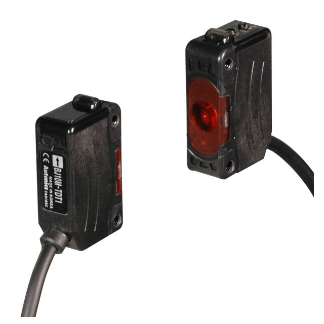
BJ Series
Compact and Long Sensing Distance Type
Features
Long distance sensing type
● �High performance lens with long sensing distance
- Through-beam type: 15m
- Diffuse reflective type: 1m
- Polarized retroreflective type: 3m (MS-2A)
● �M.S.R. (Mirror Surface Rejection) function
(polarized retroreflective type) for detecting mirrors
or highly reflective targets
● Compact size: W10.6 × H32 × L20mm
● Light ON/Dark ON operation mode switch
● Sensitivity adjuster
● �Built-in reverse polarity protection circuit and
output short overcurrent protection circuit
● �Mutual interference prevention function
(except through-beam type)
● �Excellent noise immunity and minimal influence from ambient light
● �IP65 protection structure (IEC standard) /
IP67 for BJ-C connector types
Please read “Safety Considerations”
in the instruction manual before using.
(MS-2A)
(MST- )
Connector type
※�The model name with ‘-C’
is connector type.
※MST- is sold separately.
Specifications
Type
NPN open
collector output
PNP open
collector output
Long distance sensing type
BJ15M-TDT
BJ10M-TDT
BJ7M-TDT
BJ15M-TDT-C BJ10M-TDT-C
BJ15M-TDT-P BJ10M-TDT-P
BJ7M-TDT-P
BJ15M-TDT-C-P BJ10M-TDT-C-P
Environment
Model
BJ3M-PDT
BJ1M-DDT
BJ300-DDT
BJ100-DDT
BJ3M-PDT-C
BJ1M-DDT-C BJ300-DDT-C
BJ100-DDT-C
BJ3M-PDT-P
BJ1M-DDT-P
BJ300-DDT-P
BJ100-DDT-P
BJ3M-PDT-C-P BJ1M-DDT-C-P BJ300-DDT-C-P BJ100-DDT-C-P
Polarized
Sensing type
Through-beam
Diffuse reflective
retroreflective type
※1
※2
※3
※3
Sensing distance
15m
10m
7m
3m
1m
300mm
100mm
Opaque material Opaque material
Sensing target
Opaque material of min. Ø12mm
Translucent, opaque materials
of min. Ø8mm of min. Ø75mm
Hysteresis
Max. 20% at sensing distance
Response time
Max. 1ms
Power supply
12-24VDCᜡ±10% (ripple P-P: max.10%)
Current consumption
Emitter/Receiver: Max. 20mA
Max. 30mA
Infrared LED
Red LED
Red LED
Red LED
Infrared LED Red LED
Infrared LED
Light source
(850nm)
(660nm)
(650nm)
(660nm)
(850nm)
(660nm)
(850nm)
Sensitivity adjustment
Sensitivity adjuster
Operation mode
Light ON/Dark ON operation mode switch
NPN or PNP open collector output
Control output
●Load voltage: max. 26.4VDCᜡ ●Load current: max. 100mA ●Residual voltage - NPN: max. 1VDCᜡ, PNP: max. 2.5VDC
Reverse polarity protection circuit, output short overcurrent protection circuit,
Protection circuit
mutual interference prevention function (except through-beam type)
Indicator
Operation indicator: red LED, stable indicator: green LED (emitter’s power indicator: green)
Insulation resistance
Over 20MΩ (at 500VDC megger)
Noise immunity
±240V the square wave noise (pulse width:1㎲) by the noise simulator
Dielectric strength
1000VAC 50/60Hz for 1minute
Vibration
1.5mm amplitude at frequency of 10 to 55Hz (for 1 min) in each X, Y, Z direction for 2 hours
Shock
500m/s2 (approx. 50G) in each X, Y, Z direction for 3 times
Ambient illumination Sunlight: max. 11,000lx, incandescent lamp: max. 3,000lx (receiver illumination)
Ambient temperature -25 to 55℃, storage: -40 to 70℃
Ambient humidity
35 to 85%RH, storage: 35 to 85%RH
Protection structure
BJ: IP65 (IEC standard), BJ-C: IP67 (IEC standard)
Case: polycarbonate+acrylonitrile butadiene styrene, LED cap: polycarbonate, sensing part: polymethyl methacrylate,
Material
bracket: SUS304 (steel use stainless 304), bolt, nut: steel chromium molybdenum, sleeve: brass, ni-plate
※4
BJ: �Ø3.5mm, 3-wire, 2m (emitter of through-beam type: Ø3.5mm, 2-wire, 2m)
Cable
(AWG24, core diameter: 0.08mm, number of cores: 40, insulator out diameter: Ø1mm)
Fixing bracket※5, M3 bolt: 4, M3 nut: 4,
Common
Fixing bracket※5, M3 bolt: 2, M3 nut: 2, adjustment screwdriver
adjustment
screwdriver
Accessory
Individual
Reflector (MS-2A) Approval
BJ: �approx. 85g
※6
BJ: approx. 115g (approx. 90g)
(approx. 60g) BJ: approx. 70g (approx. 45g)
Weight
BJ-C: approx. 45g (approx. 20g)
BJ-C: �approx. 55g BJ-C: approx. 35g (approx. 10g)
(approx. 30g)
※1: �The sensing distance is specified with the MS-2A reflector. The distance between the sensor and the reflector should be set over 0.1m.
The sensing distance is extended from 0.1 to 4m or 0.1 to 5m when using optional reflector MS-2S or MS-3S.
When using reflective tapes, the reflectivity will vary by the size of the tape. Please refer to the “ Reflectivity By Reflective Tape Model” table before using the tapes.
※2: Non-glossy white paper 300×300mm.
※3: Non-glossy white paper 100×100mm.
※4: M8 connector cable is sold separately. (cable - AWG22, Core diameter: 0.08mm, Number of cores: 60, Insulator out diameter: Ø1.25mm)
※6: The weight includes packaging. The weight in parenthesis is for unit only.
※5: Cable type includes bracket A and connector type includes bracket B.
※The temperature or humidity mentioned in Environment indicates a non freezing or condensation environment.
A-26
�Long Sensing Distance/BGS Reflective/Micro Spot Type
Transparent Glass Sensing/BGS Reflective/Micro Spot Type
Features
SENSORS
BGS reflective type
● �BGS (background suppression) minimizes detection errors from
background objects and the color or material of target objects.
Also the detecting distance can be configured with the sensitivity adjuster.
● �Visible light source allows users to identify the sensing area, and the tiny
spot size minimizes influence from surrounding objects
Transparent glass
Transparent glass sensing type / Micro spot type
BGS reflective
type
Commonness
● Compact size: W10.6 × H32 × L20mm
● Light ON/Dark ON operation mode switch (except BJG30-DDT)
● Sensitivity adjuster (except BJG3-DDT)
● �Built-in reverse polarity protection circuit and
output short overcurrent protection circuit
● Mutual interference prevention function (except BGS reflective type)
● Excellent noise immunity and minimal influence from ambient light
● IP65 protection structure (IEC standard)
Model
Sensing target
Min. diameter of
transmitting spot
Min. sensing target
Hysteresis
※1
※Spot is visible with bare eyes
while beam (line) is not.
Transparent glass sensing type
BJG30-DDT
Diffuse reflective
※2
※3
30mm
15mm
Transparent glass,
opaque materials, translucent
BGS reflective type
BJ30-BDT
BJ50-BDT
BJ30-BDT-P
BJ50-BDT-P
BGS reflective
※4
※4
10 to 30mm
10 to 50mm
Micro spot type
BJN50-NDT
BJN100-NDT
BJN50-NDT-P
BJN100-NDT-P
Narrow beam reflective
30 to 70mm
70 to 130mm
Translucent, opaque materials
Translucent, opaque materials
-
Approx. Ø5.0mm
Approx. Ø2.0mm
Approx. Ø4.5mm
Max. 20% at sensing distance
Max. 10% at sensing distance
(A)
Photoelectric
Sensors
(B)
Fiber Optic
Sensors
(C)
LiDAR
(D)
Door/Area
Sensors
(E)
Vision
Sensors
Approx. Ø2.5mm
Approx. min. Ø0.2mm (copper wire)
Max. 25% at
Max. 20% at
sensing distance
sensing distance
Max. 1ms
Max. 1ms
Max. 1.5ms
12-24VDCᜡ ±10% (ripple P-P: max.10%)
Max. 30mA
Infrared LED (850nm)
Red LED (660nm)
Red LED (650nm)
Sensitivity adjuster
Light ON fixed
Light ON/Dark ON operation mode switch
NPN open collector output
or PNP open collector output
●Load voltage: max. 26.4VDCᜡ NPN
Control output
●Load voltage: max. 26.4VDCᜡ ●Load current: max. 100mA
●Load current: max. 100mA
●Residual
voltage - NPN: max. 1VDCᜡ, PNP: min. 2.5VDC
●Residual voltage: max. 1V
Reverse
polarity
protection
circuit,
output
short
overcurrent protection circuit,
Protection circuit
mutual interference prevention function (except BGS reflective type)
Indicator
Operation indicator: red LED, stability indicator: green LED
Insulation resistance
Over 20MΩ (at 500VDC megger)
Noise immunity
±240V the square wave noise (pulse width:1㎲) by the noise simulator
Dielectric strength
1,000VAC 50/60Hz for 1 min
Vibration
1.5mm amplitude at frequency of 10 to 55Hz (for 1 min) in each X, Y, Z direction for 2 hours
Shock
500m/s2 (approx. 50G) in each X, Y, Z direction for 3 times
Ambient illumination Sunlight: max. 11,000lx, incandescent lamp: max. 3,000lx (receiver illumination)
Ambient temperature -25 to 55℃, storage: -40 to 70℃
Ambient humidity
35 to 85%RH, storage: 35 to 85%RH
Protection structure
IP65 (IEC standard)
Case: polycarbonate+acrylonitrile butadiene styrene, LED cap: polycarbonate, sensing part: polymethyl methacrylate,
Material
bracket: SUS304 (steel use stainless 304), bolt, nut: steel chromium molybdenum, sleeve: brass, ni-plate
Cable
Ø3.5mm, 3-wire, 2m (AWG24, core diameter: 0.08mm, number of cores: 40, insulator out diameter: Ø1mm)
Fixing bracket, M3 bolt: 2,
Accessory
Fixing bracket, M3 bolt: 2, M3 nut: 2, adjustment screwdriver
M3 nut: 2
Approval
Unit weight
Approx. 45g
Approx. 50g
Approx. 45g
※1: In case of BGS sensing type, black/white difference is max. 10% of sensing distance and sensitivity adjustment range is -10% of max.
sensing distance (based on non-glossy white paper).
※2: Non-glossy white paper 100×100mm.
※3: Transparent glass 50×50mm, t=3.0mm.
※4: Non-glossy white paper 50×50mm.
※The temperature or humidity mentioned in Environment indicates a non freezing or condensation environment.
Environment
Response time
Power supply
Current consumption
Light source
Sensitivity adjustment
Operation mode
Micro spot type
(spot size)
Ø2.0/2.5mm
-
SOFTWARE
(spot size)
Ø5.0/4.5/6.5mm
Please read “Safety Considerations”
in the instruction manual before using.
Specifications
MOTION DEVICES
sensing type
● �Stable detection of transparent targets (LCD, PDP, glass etc.)
(transparent glass sensing types)
● Check sensing area with visible micro spot (micro spot types)
● Detect tiny objects (minimum target size: Ø0.2mm copper wire)
Type
NPN open collector output
PNP open collector output
Sensing type
Sensing distance
CONTROLLERS
A-27
(F)
Proximity
Sensors
(G)
Pressure
Sensors
(H)
Rotary
Encoders
(I)
Connectors/
Connector Cables/
Sensor Distribution
Boxes/ Sockets
�BJ Series
Feature Data
Through-beam type
● BJ15M-TDT- (C)- (P) / BJ10M-TDT- (C)- (P) / BJ7M-TDT- (P)
Parallel shifting characterisitic
Measuring method Data
Angle characteristic
Measuring method Data
24
L
ℓ1
Receiver
16
Emitter
12
L
θ
8
Receiver
4
0
40
ℓ1
0
40
ℓ1
BJ10M-TDT-(C)-(P)
12
BJ7M-TDT(P)
8
4
0
80
BJ15M-TDT-(C)-(P)
16
Sensing distance L (m)
Sensing distance L (m)
Emitter
20
BJ15M-TDT-(C)-(P)
BJ10M-TDT-(C)-(P)
BJ7M-TDT(-P)
20
80
30°
Left
20°
10°
0° 10° 20° 30°
Right
Center
Operation angle (θ)
Sensing area ℓ1 (cm)
Retroreflective type
● BJ3M-PDT- (C)- (P)
Parallel shifting characterisitic
Measuring method Data
Sensor angle characteristic
Measuring method Data
Reflector angle characteristic
Measuring method Data
MS-2A
3.0
θ
L
2.0
1.0
0
160 80
ℓ1
0
ℓ1
Reflector (MS-2)
4.0
3.0
θ
2.0
Sensing area ℓ1 (mm)
0°
5° 10°
Center
Right
Operation angle (θ)
●�BJ300-DDT- (C)- (P)
Sensing area characteristic
Measuring method Data
ℓ1
1200
Standard
sensing
target
800
L
400
200
0
40 20
ℓ1
0
ℓ1
20
600
400
200
A-28
Standard
sensing
target
15
L
Sensing distance L (mm)
Sensing distance L (mm)
ℓ1
0
20 15 10 5 0 5 10 15 20
ℓ1 ℓ1
20
120
80
40
20
0
ℓ1
40 20
ℓ1
20
40
●�BJN100-NDT- (P)
Sensing area characteristic
Measuring method Data
180
160
ℓ1
80
Standard
sensing
target
60
L
40
20
0
0
ℓ1
Sensing area ℓ1 (mm)
Sensing area characteristic
Measuring method Data
100
5
10
● �BJN50-NDT- (P)
25
10
0
160
Sensing area ℓ1 (mm)
120
Sensing area ℓ1 (mm)
10
ℓ1
30
20
Standard
sensing
target
L
40
●B
� JG30-DDT
L
200
ℓ1
0
20
Sensing area characteristic
Measuring method Data
Standard
sensing
target
0.5
Sensing area characteristic
Measuring method Data
800
Sensing area ℓ1 (mm)
ℓ1
1.5
Sensing distance L (mm)
L
2.5
1000
1600
Sensing distance L (mm)
Standard
sensing
target
Sensing distance L (mm)
ℓ1
3.5
●B
� J100-DDT- (C)- (P)
Sensing area characteristic
Measuring method Data
2000
4.5
0.0
40° 20° 0° 20° 40°
Center
Left
Right
Operation angle (θ)
5°
Diffuse/Narrow beam reflective type
● �BJ1M-DDT- (C)- (P)
L
1.0
0.0
10°
Left
80 160
Sensing distance L (m)
Reflector (MS-2)
4.0
5.0
2
1
0
ℓ1 ℓ1
1
Sensing area ℓ1 (mm)
2
Sensing distance L (mm)
ℓ1
5.0
Sensing distance L (m)
Reflector (MS-2)
Sensing distance L (m)
6.0
140
120
100
80
60
40
20
0
2
1
ℓ1
0
ℓ1
1
Sensing area ℓ1 (mm)
2
�Long Sensing Distance/BGS Reflective/Micro Spot Type
Feature Data
BGS reflective type
SENSORS
● �BJ30-BDT / BJ30-BDT-P
Sensing area characteristic
Measuring method Data
Sensing distance by material
Sensing distance by color
CONTROLLERS
ℓ1
L
25
20
15
10
5
0
40
Sensing distance L (mm)
Standard
sensing
target
40
30
Sensing distance L (mm)
Sensing distance L (mm)
35
30
20
10
0
2.0 1.0 0 -1.0 -2.0
1.5 0.5 -0.5 -1.5
White Corrugated Black Rubber SUS PCB
Acryl
paper cardboard paper (black)
(green) (transparent)
MOTION DEVICES
30
20
SOFTWARE
10
0
White Red OrangeYellowGreen Blue Navy Violet Black
Sensing target (colored paper)
Sensing target (material)
ℓ1
ℓ1
Sensing area ℓ1 (mm)
(A)
Photoelectric
Sensors
● BJ50-BDT / BJ50-BDT-P
Sensing area characteristic
Measuring method Data
3
2
1
50
40
30
20
10
0
0 -1 -2 -3
ℓ1
(B)
Fiber Optic
Sensors
60
Sensing distance L (mm)
L
Sensing distance by color
60
Sensing distance L (mm)
Sensing distance L (mm)
ℓ1
Standard
sensing
target
60
55
50
45
40
35
30
25
20
15
10
5
0
Sensing distance by material
(C)
LiDAR
50
40
(D)
Door/Area
Sensors
30
20
(E)
Vision
Sensors
10
0
White Corrugated Black Rubber SUS PCB
Acryl
paper cardboard paper (black)
(green) (transparent)
White Red OrangeYellowGreen Blue Navy Violet Black
(F)
Proximity
Sensors
Sensing target (colored paper)
Sensing target (material)
ℓ1
Sensing area ℓ1 (mm)
(G)
Pressure
Sensors
(H)
Rotary
Encoders
Connections
● Through-beam type
Brown
Brown
+
- Blue
Black
Sensing
target
Blue
※1
※2
● �Diffuse/Narrow beam/
BGS reflective type
●�Retroreflective type
Brown
Brown
Load
Load
+
-
Reflector (MS-2)
Reflective tape
(MST Series)
Sensing
target
※1: Load connection for NPN output
※2: Load connection for PNP output
Black
Blue
※1
※2
(I)
Connectors/
Connector Cables/
Sensor Distribution
Boxes/ Sockets
Load
Load
+
-
Sensing
target
Black
Blue
※1
Load
※2
Load
+
-
Connections for Connector Part
① ②
③ ④
M8 Connector pin
Connector pin No. Cable colors
Function
①
Brown
Power Source (+V)
②
White
-
③
Blue
Power Source (0V)
● Connector cable (sold separately)
※Connector cable model
: CID408- , CLD408※�Please refer to the connector cable section.
④
Black
Output
※Connector pin ② is N.C (not connected) terminal.
A-29
�BJ Series
Control Output Diagram
● NPN open collector output
Photoelectric sensor circuit
Connection
● PNP open collector output
Photoelectric sensor circuit
Output short
over current
protection
circuit
Load
Max.100mA
+
-
12-24VDC
(blue)0V
Main circuit
Main circuit
(black)output
Connection
(brown)+V
(brown)+V
Output short
over current
protection
circuit
Max.100mA
+
-
(black)output
(blue)0V
12-24VDC
Load
※�If short-circuit the control output terminal or supply current over the rated specification,
normal control signal is not output due to the output short over current protection circuit.
Operation Mode
Operation mode
Receiver operation
Operation indicator
(red LED)
Transistor output
Light ON
Received light
Interrupted light
ON
OFF
ON
OFF
Dark ON
Received light
Interrupted light
ON
OFF
ON
OFF
Dimensions
(unit: mm)
●Through-beam type
●Through-beam type (connector type)
Power indicator
(green)
Stability indicator
(green)
Operation indicator
(red)
2-Ø3.2
3
32
2.7
3
15
15
25
15
32
4
Power indicator
(green)
20
2.7
Operation 10.6 Stability
indicator
indicator
(green)
(red)
10.6
20
Ø3.5, 2m
● Retroreflective type
● Retroreflective type (connector type)
Operation 10.6 Stability
indicator
indicator
(green)
(red)
Stability indicator
(green)
Operation indicator
(red)
2-Ø3.2
32
44
2.7
3
15
15
25
15
8
32
4
20
2.7
Stability indicator
(green)
Operation indicator
(red)
10.6
20
Ø3.5, 2m
A-30
3
�Long Sensing Distance/BGS Reflective/Micro Spot Type
● Bracket B
42.5
25
3
2-6
18
35
R2
5
Ø3.4
MOTION DEVICES
R1.7
SOFTWARE
R1.7
20°
12.5
1.2
CONTROLLERS
14
8
Ø3.4
22
15
2.5
8.5
3.25
SENSORS
Ø3.4
36
26.5
R25
34
40.5
3.4
14
8
3.4
4.2
17
5 3
52
60.5
2-Ø3.8
● Bracket A
1.2
● Reflector(MS-2A)
10°
※Cable type provides the bracket A and connector type provides the bracket B.
The other bracket is also avilable as sold separately.
(A)
Photoelectric
Sensors
Reflective tape (sold separately)
A
0.38
(B)
Fiber Optic
Sensors
(unit: mm)
Model
A
MST-50-10
50
MST-100-5
100
MST-200-2
200
(C)
LiDAR
(D)
Door/Area
Sensors
(E)
Vision
Sensors
Operation Timing Diagram
● Through-beam type
Stable
light ON area
Unstable
operation area
Stable
light OFF area
● Retroreflective/Diffuse/Narrow beam/
BGS reflective type
High
Incident
light
level
Stable
light ON area
Operation
level
Unstable
light ON area
Unstable
light OFF area
(G)
Pressure
Sensors
High
(H)
Rotary
Encoders
Incident
light
level
Operation
level
Stable
light OFF area
Low
Stability
ON
indicator
(green LED) OFF
Low
Stability
ON
indicator
(green LED) OFF
Light ON
operation
(F)
Proximity
Sensors
Operation
indicator
(red LED)
ON
OFF
Transistor
output
ON
OFF
Light ON
operation
Operation
indicator
(red LED)
ON
OFF
Transistor
output
ON
OFF
※The waveforms of “Operation indicator” and “Transistor output” are for Light ON operation.
They are opposite operation for Dark ON operation.
Mounting and Adjustment
For mounting
When using the reflective type photoelectric sensors closely over three units, it may result in
malfunction due to mutual interference.
When using the through-beam type photoelectric sensors closely over two units, it may result in
malfunction due to mutual interference.
When installing the product, tighten the screw with a tightening torque of 0.5N.m.
M3×18mm
A-31
(I)
Connectors/
Connector Cables/
Sensor Distribution
Boxes/ Sockets
�BJ Series
Switching of operation mode
Light ON
operation
Dark ON
operation
D
Turn the operation mode switch to the
end of right (L direction), it is set as
Light ON.
L
D
Sensitivity adjustment
L
Order Position
1
Turn the operation mode switch to the
end of left (D direction), it is set as Dark
ON.
※�For through-beam type, the operation mode switch is builtin the receiver.
2
Optical axis adjustment
●Through-beam type
1. Place the emitter and the
Receiver
Adjust
receiver facing each other and
Right/Left
supply the power.
Emitter
s
2. After adjusting the position of
axi
tic
Op
the emitter and the receiver
and checking their stable
Adjust Up/Down
indicating range, mount them
in the middle of the range.
3. After mounting this unit, check the operation of the sensor
and lighting of the stability indicator in both status. (none
or sensing target status)
※When the sensing target is translucent or small (under
sensing target of ‘ Specifications’), it may not be
detected by the sensor because the light can penetrate it.
● Retroreflective type
1.Place the sensor and the reflector
Adjust
(or reflective tape) facing each
Right/Left
other and supply the power.
2.After adjusting the position of the
sensor and reflector (or reflective
Reflector (MS-2A)
tape) and checking their stable
Reflective tape
indicating range, mount them in
(MST Series)
the middle of the range. (none or
Adjust Up/Down
sensing target status)
3.After mounting this unit, check the operation of the
sensor and in both status. (none or sensing target status)
※Please use reflective tape (MST Series) for where a
reflector is not installed.
● Diffuse/Narrow beam/BGS reflective type
After placing a sensing target,
adjust the sensor to up or down,
right or left.
Then, fix the sensor in the center
of position where the stability is
operating.
Sensing
target
● Object (copper wire) detection
[Figure 1]
When copper
wire is moved.
Copper
wire
[Figure 2]
Approx. 0 to 15°
Copper
wire
※Mount the sensor slanted at an angle ranged 0 to 15˚ shown
above as [Figure 2] for stable detection to detect as shown
in [Figure 1].
A-32
Description
Turn the sensitivity adjuster to the right
of min. and check position (A) where the
operation indicator is turned ON in “Light
MIN. MAX. ON status”.
Turn the sensitivity adjuster more to the
right of position (A), check position (B)
where the operation indicator is turned ON.
(A)
(C)
And turn the sensitivity adjuster to the
left, check position (C) where the operation
indicator is turned OFF in “Light OFF
(B) status”.
※If the operation indicator is not turned
MIN. MAX.
ON although the sensitivity adjuster
is turned to the max. position, the max.
position is (C).
Set the sensitivity adjuster at the center
Optimal
of (A) and (C). To set the optimum
sensitivity
sensitivity, check the operation and
(C) lighting of stability indicator with sensing
(A)
target or without it. If the stability
indicator is not turned ON, please check
the sensing method again because
MIN. MAX.
sensitivity is unstable.
(A)
3
※No sensitivity adjustment function available for BJG30DDT models.
Light ON status
Throughbeam
type
Retroreflective
type
Emitter
Receiver
Sensor
Reflector
Diffuse/
Narrow
beam/
Sensor
BGS
reflective
Sensing
target
Background
object
Light OFF status
Emitter
Sensor
Sensor
Sensing
target
Receiver
Sensing
target Background
object
Background
object
※Set the sensitivity to operate in stable light ON area and
the reliability for the environment (temperature, voltage,
dust etc) is increased. In unstable light ON area, be sure
to check the variation of environment.
※Do not apply excessive force on the sensitivity adjuster
or operation mode switch, they may be broken.
※Please use reflective tape (MST Series) for where a
reflector is not installed.
Reflectivity by Reflective Tape
Model
MST-50-10(50×50mm)
40%
MST-100-5(100×100mm)
60%
MST-200-2(200×200mm)
100%
※This reflectivity is based on the reflector (MS-2A).
※Reflectivity may vary depending on usage environment
and installation conditions.
The sensing distance and minimum sensing target size
increase as the size of the tape increases.
Please check the reflectivity before using reflective
tapes.
※For using reflective tape, installation distance should be
min. 20mm.
�