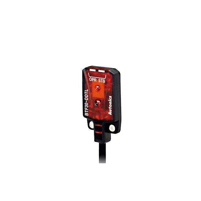
BTF Series
Ultra-slim and Amplifier Built-in Type
Features
SENSORS
●U
� ltra-thin size of only 3.7mm
- W13 × H19 × L3.7mm (through-beam type)
- W13 × H24 × L3.7mm (diffuse reflective type, BGS reflective type)
●D
� etection methods and minimum target size
- Through-beam type (BTF1M): Ø2mm
- Diffuse reflective type (BTF30): Ø0.2mm (at distance 10mm)
- BGS reflective type (BTF15): Ø0.2mm (at distance 10mm)
● Detecting distance may vary by environmental factors
● Maximum detection distance: 1m (through-beam type)
● Stability indicator (green LED) and operation indicator (red LED)
● Stainless steel 304 mounting brackets
● IP67 protection structure (IEC standard)
Please read “Safety Considerations”
in the instruction manual before using.
CONTROLLERS
MOTION DEVICES
Through-beam
SOFTWARE
Diffuse reflective /
BGS reflective
(A)
Photoelectric
Sensors
(B)
Fiber Optic
Sensors
Model
Specifications
NPN open collector output BTF1M-TDTL
BTF1M-TDTD
PNP open collector output BTF1M-TDTL-P
BTF1M-TDTD-P BTF30-DDTL-P
BTF30-DDTL
BTF30-DDTD
BTF15-BDTL
BTF15-BDTD
BTF30-DDTD-P
BTF15-BDTL-P
BTF15-BDTD-P
Sensing type
Sensing distance
Sensing target
Through-beam
1m
Opaque material over Ø2mm
Min. sensing target
Opaque material of Ø2mm
Hysteresis
Reflectivity characteristics
(black/white error)
Response time
Power supply
Current consumption
Light source
Operation mode
-
Diffuse reflective
5 to 30mm※1
Translucent, opaque materials
Ø0.2mm
(sensing distance 10mm)
Max. 20% at sensing distance
-
-
BGS reflective
1 to 15mm※1
(C)
LiDAR
(D)
Door/Area
Sensors
Ø0.2mm non-illuminated objects
(sensing distance 10mm)
Max. 5% at sensing distance
Max. 15% of maximum
sensing distance
(E)
Vision
Sensors
(F)
Proximity
Sensors
Max. 1ms
12-24VDCᜡ ±10% (ripple P-P: max. 10%)
Max. 20mA (this is for each emitter and receiver of throught-beam type.)
Red LED (650nm)
Light ON
Dark ON
Light ON
Dark ON
Light ON
Dark ON
NPN or PNP open collector output
Control output
• Load voltage: max. 26.4VDCᜡ
• Load current: max. 50mA
• Residual voltage - NPN: max. 1VDCᜡ, PNP: max. 2VDC
Protection circuit
Power reverse polarity protection circuit, output short over current protection circuit
Indicator
Operation indicator: red LED, stability indicator: green LED
Connection
Cable type
Insulation resistance
Over 20MΩ (at 500VDC megger)
Noise immunity
±240V the square wave noise (pulse width:1㎲) by the noise simulator
Dielectric strength
1,000VAC 50/60Hz for 1 minute
Vibration
1.5mm amplitude at frequency of 10 to 55Hz in each X, Y, Z direction for 2 hours
Shock
500m/s² (approx. 50G) in each X, Y, Z direction for 3 times
Ambient illumination Sunlight: max. 10,000lx, incandescent lamp: max. 3,000lx (receiver illumination)
EnvironAmbient temperature -25 to 55℃, storage: -40 to 70℃
ment
Ambient humidity 35 to 85%RH, storage: 35 to 85%RH
Protection
IP67 (IEC standards)
Case: polybutylene terephthalate, sensing part: polymethyl methacrylate,
Material
bracket: SUS304 (steel use stainless 304), bolt: carbon steel, sleeve: SUS304 (steel use stainless 304)
Ø2.5mm, 3P, 2m (emitter of through-beam type: Ø2.5mm, 2P, 2m)
Cable
(AWG 28, core diameter: 0.08mm, number of core: 19, insulator out diameter: Ø0.9mm)
Accessory
Fixing bracket, M2 bolt: 4
Fixing bracket, M2 bolt: 2
Approval
Weight※2
Approx. 70g (approx. 40g)
Approx. 40g (approx. 25g)
(G)
Pressure
Sensors
(H)
Rotary
Encoders
(I)
Connectors/
Connector Cables/
Sensor Distribution
Boxes/ Sockets
※1: Non-glossy white paper 50×50mm.
※2: The weight includes packaging. The weight in parenthesis is for unit only.
※The temperature or humidity mentioned in Environment indicates a non freezing or condensation.
A-15
�BTF Series
Feature Data
Diffuse reflective type
Through-beam type
● BTF1M-TDTL / BTF1M-TDTL-P
● BTF30-DDTL / BTF30-DDTL-P
Sensing area characteristic
Measuring method
Data
Sensing area characteristic
Measuring method
Data
1.6
Emitter
ℓ1
L
Receiver
Sensing distance L (mm)
Sensing distance L (m)
1.4
1.2
1.0
Standard
ℓ1 sensing
target
0.8
0.6
0.4
L
0.2
0
60 40 20 0 20 40 60
ℓ1
ℓ1
50
45
40
35
30
25
20
15
10
0
3 2 1 0 1 2 3
ℓ1
ℓ1
Sensing area (mm)
Sensing area (mm)
BGS reflective type
● BTF15-BDTL / BTF15-BDTL-P
Sensing area characteristic
Measuring method
Data
Standard
sensing
target
L
Sensing distance L (mm)
Sensing distance L (mm)
ℓ1
Sensing distance by material
18
16
14
12
10
9
6
4
2
0
3 2 1 0 1 2 3
ℓ1
ℓ1
20
15
10
5
0
White
paper
Black
paper
PCB
(green)
SUS304
Acrylic
(transparent)
Sensing target (material)
Sensing area (mm)
Connections
Control Output Circuit Diagram
● Through-beam type
● NPN open collector output
Photoelectric sensor circuit Connection
Main circuit
(brown) +V
Sensing target
(brown) +V
12-24VDC
(blue) 0V
(brown) +V
+
-
1 Load
(black) Output
2 Load
(blue) 0V
Load
(black) Output
Output short
over current
protection
circuit
Max. 50mA
+
-
12-24VDC
+
-
12-24VDC
(blue) 0V
● PNP open collector output
● Diffuse reflective/BGS reflective type
Photoelectric sensor circuit Connection
Main circuit
(brown) +V
Sensing target
(brown) +V
(black) Output
(blue) 0V
1: Load connection for NPN output
2: Load connection for PNP output
A-16
Load 1
12-24VDC
Load
2
+
-
Output short
over current
protection
circuit
Max. 50mA
(black) Output
(blue) 0V
Load
※�If short-circuit the control output terminal or supply
current over the rated specification, normal control
signal is not output due to the output short over current
protection circuit.
�Ultra-slim and Amplifier Built-in Type
Operation Mode
Operation mode
Receiver operation
Light ON
SENSORS
Dark ON
Received light
Received light
Interrupted light
Interrupted light
ON
ON
OFF
OFF
Operation indicator
(red LED)
Transistor output
ON
ON
OFF
OFF
CONTROLLERS
MOTION DEVICES
SOFTWARE
Dimensions
(unit: mm)
● Through-beam type
1.2
(A)
Photoelectric
Sensors
9
(B)
Fiber Optic
Sensors
15.5
Operation indicator (red)
Optical axis
of emitter
Stability indicator (green)
3.7 6.8
(C)
LiDAR
2-M3
8
(E)
Vision
Sensors
4
4
4
Optical axis
of receiver
16
2.4
8.6
18
8.6
19
(D)
Door/Area
Sensors
(F)
Proximity
Sensors
2-2M
13
(G)
Pressure
Sensors
3.2
8
Ø2.5, 2m
4.6
10.3
(H)
Rotary
Encoders
● Diffuse reflective/BGS reflective type
1.2
(I)
Connectors/
Connector Cables/
Sensor Distribution
Boxes/ Sockets
9
15.5
Operation indicator (red)
Stability indicator (green)
3.7
6.8
8
2.4
4
4
Optical axis of emitter
16
4.8
Optical axis of receiver
7.9
23
24
2-M3
2-2M
Ø2.5, 2m
3.2
8
13
4.6
10.3
A-17
�BTF Series
Operation Timing Diagram
High
Stable light ON area
Unstable light ON area
Unstable light OFF area
Incident
light
level
Operation
level
Stable light OFF area
Low
Stability indicator ON
(green LED) OFF
Light ON
operation
Operation indicator ON
(red LED) OFF
Transistor output
ON
OFF
※�The waveform of ‘Operation indicator’ and ‘Transistor output’ are for Light ON operation.
The waveform are reversed for Dark ON operation.
Installation and Adjustment
For mounting
Notice for BGS reflective type
When using photoelectric sensors closely over two units,
it may result in malfunction due to mutual interference.
When installing the product, tighten the screw with a
tightening torque of 0.3N.m.
※�Do not impact on the unit with hard objects and do not
bend the cable part too much. It may cause damage to
waterproof function.
● Through-beam type
4-M2 Tap×0.4mm
M2×4mm
● Diffuse reflective/BGS reflective type
1) Make sure that the sensing side
of this sensor is parallel with the
surface of each sensing object.
2) If the sensing object has glossary
surface or high reflection, the
sensor tilts from 5 to 10˚as
shown in the figure.
Make sure whether the sensor is
influenced by any background
objects.
Sensing
target
5 to 10°
Glossy materials
3) Make sure to install the sensor in the proper direction with
considering moving direction of sensing objects.
Sensing
Refer to the following.
4-M2 Tap×0.4mm
Sensing
target
M2×4mm
Sensing
target
target
Moves
vertically
Moves
horizontally
Optical axis adjustment
● Through-beam type
Set the emitter and the receiver facing each other and adjust
these up·down, right·left after checking the point of operating
the stability indicator. Fix the emitter and the receiver at the
center of the point.
Adjust
Right/Left
A-18
● Diffuse reflective/BGS reflective type
After placing a sensing target, fix it in the middle of position
where the stability indicator operates when adjusting the
sensor to up·down, right·left. Make sure that the sensing
side of the sensor is parallel with the surface of each sensing
target.
Adjust
Right/Left
Adjust
Up/Down
Moves
back and forth
Sensing target
Adjust
Up/Down
�
很抱歉,暂时无法提供与“BTF15-BDTD-P”相匹配的价格&库存,您可以联系我们找货
免费人工找货