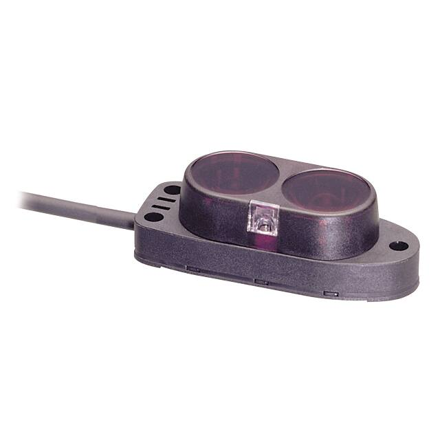
BA Series
Small, Diffuse Reflective Type with Long Sensing Distance
SENSORS
Features
● Realization of long sensing distance (2m) by special optical design
● Protection structure IP64 (IEC standard)
● Built-in stability indicator
● Includes sensitivity adjustment function
● 2 color LED display
CONTROLLERS
MOTION DEVICES
SOFTWARE
Please read “Safety Considerations”
in the instruction manual before using.
Specifications
Model
(A)
Photoelectric
Sensors
NPN open collector BA2M-DDT
BA2M-DDTD
PNP open collector BA2M-DDT-P
BA2M-DDTD-P
Sensing type
Diffuse reflective
Sensing distance
2m (non-glossy white paper 200×200mm)
Sensing target
Translucent, opaque materials
Hysteresis
Max. 20% at sensing distance
Response time
Approx. 1ms
Power supply
12-24VDC
Current consumption
Max. 15mA (max. 30mA when the output is ON)
Light source
Infrared LED (850nm)
Sensitivity adjustment
Sensitivity adjuster
Operation mode
Light ON
Control output
NPN or PNP open collector output
●Load voltage: max. 26.4VDC
●Load current: max. 100mA
●Residual voltage - NPN: max. 1VDCᜡ, PNP: min. 2.5VDC
Protection circuit
Reverse polarity protection circuit, output short overcurrent protection circuit
Indicator
●Operation indicator: red LED
Insulation resistance
Over 20MΩ (at 500VDC megger)
Noise immunity
±240V the square wave noise (pulse width: 1㎲) by the noise simulator
Dielectric strength
1000VAC 50/60Hz for 1 minute
Vibration
1.5mm amplitude at frequency of 10 to 55Hz (for 1 min) in each X, Y, Z direction for 2 hours
Shock
100m/s² (approx. 10G) in each X, Y, Z direction for 3 times
(B)
Fiber Optic
Sensors
(C)
LiDAR
(D)
Door/Area
Sensors
±10% (ripple P-P: max. 10%)
(E)
Vision
Sensors
(F)
Proximity
Sensors
Dark ON
(G)
Pressure
Sensors
(H)
Rotary
Encoders
●Stability indicator: orange LED (light on), green LED (dark on)
(I)
Connectors/
Connector Cables/
Sensor Distribution
Boxes/ Sockets
Ambient illumination Sunlight: max. 11,000㏓, incandescent lamp: max. 3,000㏓ (receiving illumination)
EnvironAmbient temperature -25 to 55℃, storage: -25 to 70℃
ment
Ambient humidity
35 to 85%RH, storage: 35 to 85%RH
Protection structure
IP64 (IEC standard)
Material
Case: acrylonitrile butadiene styrene, sensing part: polycarbonate, indicator: polycarbonate, adjuster: IXEF
Cable
Ø3mm, 3-wire, 2m
(AWG24, core diameter: 0.08mm, number of cores: 40, insulator out diameter: Ø1mm)
Accessory
Adjuster driver
Approval
Unit weight
Approx. 50g
※The temperature or humidity mentioned in Environment indicates a non freezing or condensation environment.
A-55
�BA Series
Feature Data
Sensing distance
against the target size
ℓ1
2.2
2.0
1.8
1.6
1.4
1.2
1.0
0.8
0.6
0.4
0.2
0
Sensing distance L (m)
Sensing
target
Sensing distance L (m)
Sensing area characteristic
60 40 20 0 20 40 60
ℓ1
ℓ1
Center
Left
2.2
2.0
1.8
1.6
1.4
1.2
1.0
0.8
0.6
0.4
0.2
0
Sensing distance
against the target color
(%)
75
60
45
Black
30
15
0
50
80
100
150
200
In case non-glossy white paper is 100%
(standard targets: 200×200mm)
Sensing area (mm)
Control Output Diagram
● NPN open collector output
● PNP open collector output
Photoelectric sensor circuit Connection
Photoelectric sensor circuit Connection
Output short
over current
protection
circuit
(brown) +V
Load
Max. 100mA
+
-
Main circuit
Main circuit
(brown) +V
(black) Output
Blue
90
Sensing target size (mm)
Right
White Yellow Red
100
12-24VDC
(blue) 0V
Output short
over current
protection
circuit
Max. 100mA
+
-
(black) Output
12-24VDC
Load
(blue) 0V
※�If short-circuit the control output terminal or supply current over the rated specification, normal control signal is not output
due to the output short over current protection circuit.
Connections
(brown)
(blue)
Sensing
target
+
12-24VDC
-
(black)Output
Dimensions
(unit: mm)
4.7
18.5
3.5
16
M3 Bolt
Ø3, 2m
A-56
10
8
7.5
2color LED
(operation/stability
indicator)
15.5
41.5
16
48.5
34.5
Sensitivity adjuster
19
�Diffuse Reflective Type with Long Sensing Distance
Operation Mode
If the control output terminal is short-circuit or over current than the rated current flows the unit, the sensor does not
operate normally by protection circuit.
SENSORS
● Light ON
Stable light ON area
Unstable light ON area
Unstable light OFF area
Stable light OFF area
Stability indicator
(orange LED)
Light ON
operation
CONTROLLERS
High
MOTION DEVICES
Incident
light
level
SOFTWARE
Low
ON
OFF
Operation indicator ON
(red LED)
OFF
Transistor output
(A)
Photoelectric
Sensors
ON
OFF
(B)
Fiber Optic
Sensors
(control output according to amount of receiving light)
● Dark ON
Stable light ON area
Unstable light ON area
Unstable light OFF area
Stable light OFF area
Stability indicator
(green LED)
Light ON
operation
Operation
level
High
(C)
LiDAR
Incident
light
level
(D)
Door/Area
Sensors
Operation
level
(E)
Vision
Sensors
Low
(F)
Proximity
Sensors
ON
OFF
Operation indicator ON
(red LED)
OFF
(G)
Pressure
Sensors
ON
OFF
(H)
Rotary
Encoders
Transistor output
(control output according to amount of receiving light)
Mounting and Sensitivity Adjustment
Install the sensor to the desired place and check the connections.
Supply the power to the sensor and adjust the optical axis and the sensitivity as follow ;
When using photoelectric sensors closely over two units,
● Adjustment
it may result in malfunction due to mutual interference.
1. When sensing the object, set the sensitivity adjuster in
When installing the product, tighten the screw with a
stable Light ON area (orange: Light ON, green: Dark
tightening torque of 0.5N.m.
ON) as shown ‘ Operation mode’.
● Optical axis adjustment
2. The sensitivity should be adjusted depending on a
sensing target or mounting place.
ⓐ
3. Set the target at a position to be detected by the beam,
Optimal
then turn the sensitivity adjuster until position ⓐ where
position
Sensing
the operation indicator turns ON from min. position of the
target
sensitivity adjuster
ⓑ
4.
Take the target out of the sensing area, then turn the
MIN.
MAX.
sensitivity adjuster until position ⓑ where the operation
indicator turns ON. If the indicator dose not turn ON,
max. position is ⓑ.
Mount this unit at the center where the stability indicator
5. Set the sensitivity adjuster at the center of two switching
turns ON with moving the unit toward right or left, up or
position ⓐ, ⓑ.
down.
※The sensing distance indicated on specification chart is
for 200×200mm of non-glossy white paper. Be sure that
it can be different by size, surface and gloss of target.
A-57
(I)
Connectors/
Connector Cables/
Sensor Distribution
Boxes/ Sockets
�
很抱歉,暂时无法提供与“BA2M-DDT”相匹配的价格&库存,您可以联系我们找货
免费人工找货