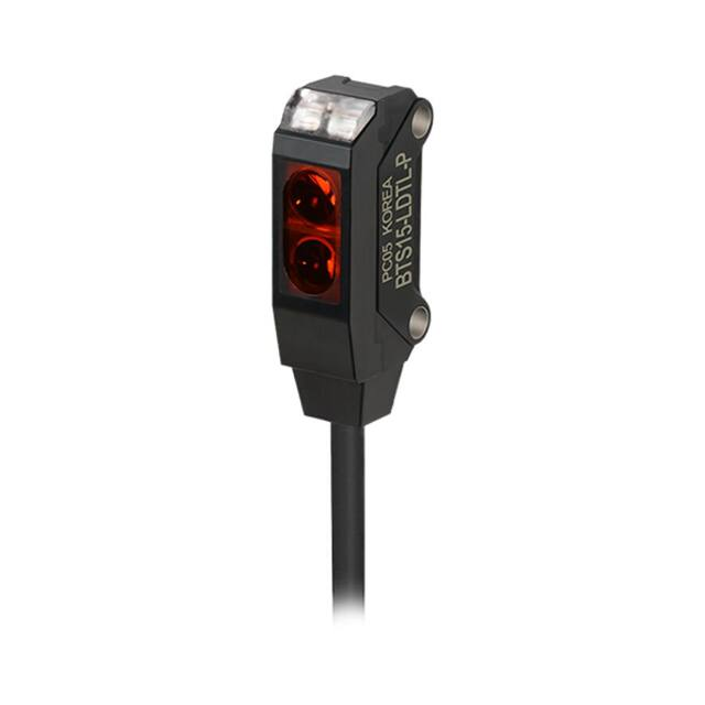
BTS Series
Ultra-compact and Amplifier Built-in Type
Features
SENSORS
� ltra-slim width of only 7.2mm
U
- W7.2×H18.6×L9.5mm (through-beam type)
- �W7.2×H24.6×L10.8mm
(retroreflective type, convergent reflective type)
�Detection methods and minimum target size
- Through-beam type (BTS1M): Ø2mm
- Retroreflective type (BTS200): Ø2mm (at distance 100mm)
- Convergent reflective type (BTS15/BTS30):
Ø0.15mm (at distance 10mm)
※Detecting distance may vary by environmental factors
Maximum detection distance: 1m (through-beam type)
Stability indicator (red LED) and operation indicator (green LED)
Stainless steel 304 mounting brackets
IP67 protection structure (IEC standard)
Please read “Safety Considerations”
in the instruction manual before using.
Specifications
Model
NPN open
collector output
PNP open
collector output
Sensing type
Sensing distance
Sensing target
Min. sensing
target
Hysteresis
distance
Response time
Power supply
Current
consumption
Light source
Operation mode
BTS1M-TDTL BTS1MTDTD
BTS1MBTS1MTDTL-P
TDTD-P
Through-beam type
1m
Opaque material of max.
Ø2mm
CONTROLLERS
MOTION DEVICES
Through-beam type
SOFTWARE
Retroreflective type/
Convergent reflective type
BTS30-LDTL BTS30-LDTD BTS15-LDTL BTS15-LDTD
Opaque material of Ø2mm
BTS200BTS200MDTL
MDTD
BTS200BTS200MDTL-P
MDTD-P
Retroreflective type
※1
10 to 200mm
Opaque material of max.
Ø27mm
※3
Opaque material of Ø2mm
(sensing distance 100mm)
-
-
Max. 15% of maximum sensing distance
BTS30BTS30LDTL-P
LDTD-P
Convergent reflective type
※2
5 to 30mm
BTS15LDTL-P
5 to 15mm
BTS15LDTD-P
(A)
Photoelectric
Sensors
(B)
Fiber Optic
Sensors
※2
Opaque material, Translucent materials
(C)
LiDAR
Ø0.15mm
(sensing distance 10mm)
(D)
Door/Area
Sensors
Max. 1ms
12-24VDCᜡ±10% (ripple P-P: max. 10%)
(E)
Vision
Sensors
Max. 20mA (in case of through-beam type, this value is for each emitter and receiver)
Environment
Red LED (650nm)
Light ON
Dark ON
Light ON
Dark ON
Light ON
Dark ON
Light ON
Dark ON
NPN or PNP open collector output
Control output
·Load voltage: max. 26.4VDCᜡ ·Load current: max. 50mA ·Residual voltage - NPN: max. 1VDCᜡ, PNP: max. 2VDC
Protection circuit Power reverse polarity protection circuit, output short over current protection circuit
Indicator
Operation indicator: red LED, stability indicator: green LED
Connection
Cable type
Insulation
Over 20MΩ (at 500VDC megger)
resistance
Noise immunity ±240V the square wave noise (pulse width: 1㎲) by the noise simulator
Dielectric
1,000VAC 50/60Hz for 1 min
strength
Vibration
1.5mm amplitude at frequency of 10 to 55Hz (for 1 min) in each X, Y, Z direction for 2 hours
Shock
500m/s² (approx. 50G) in each X, Y, Z direction for 3 times
Ambient
Sunlight: max. 10,000lx, incandescent lamp: max. 3,000lx (receiver illumination)
illumination
Ambient
temperature -20 to 55℃, storage: -30 to 70℃
Ambient
35 to 85%RH, storage: 35 to 85%RH
humidity
Protection structure IP67 (IEC standard)
Case: polybutylene terephthalate, sensing part: polymethyl methacrylate, bracket: stainless steel 304,
Material
Bolt: carbon steel wire for cold heading (SWCH10A)
Ø2.5mm, 3-wire, 2m (emitter of through-beam type: Ø2.5mm, 2-wire, 2m)
Cable
(AWG 28, core wire diameter: 0.08mm, number of cores: 19, insulator out diameter: Ø0.9mm)
Bracket A: 2, sub-bracket for Reflector (MS-6),bracket A,
Accessory
through-beam type: 2,
Sub-bracket for reflective
Bracket A, sub-bracket for reflective type, M2 bolt: 2
M2 bolt: 4
type, M2 bolt: 2
Approval
※4
Weight
Approx. 65g (approx. 40g)
Approx. 45g (approx. 25g)
※1: �The sensing distance is specified with using the MS-6 reflector.
When using reflective tapes, the Reflectivity vary by the size of the tape.
Please refer to the ‘ Reflectivity by Reflective Tape Model’ table before using the tape.
※2: Non-glossy white paper 50×50mm.
※3: It will vary by the installation environment and sensing conditions.
Please refer to the ‘ Conditions of min. sensing target and installations (retroreflective type)’.
※4: The weight includes packaging. The weight in parenthesis is for unit only.
※The temperature or humidity mentioned in Environment indicates a non freezing or condensation.
A-19
(F)
Proximity
Sensors
(G)
Pressure
Sensors
(H)
Rotary
Encoders
(I)
Connectors/
Connector Cables/
Sensor Distribution
Boxes/ Sockets
�BTS Series
Feature Data
Retroreflective type
Through-beam type
BTS200-MDTD / BTS200-MDTD-P
● BTS1M-TDTL / BTS1M-TDTL-P
Parallel shifting characteristic
Measuring method
Parallel shifting characteristic
Data
Measuring method
Data
1.8
70
Emitter
L
ℓ1
Receiver
1.4
Sensing distance L (cm)
Sensing distance L (m)
1.6
Reflector (MS-6)
1.2
1.0
ℓ1
0.8
L
0.6
0.4
0.2
60 40 20
ℓ1
0
20 40
ℓ1
60
50
40
30
20
10
0
1.5
60
Retroreflective type
Sensing area ℓ1 (mm)
1 0.5
ℓ1
0
0.5 1 1.5
ℓ1
Center
Left
Right
Sensing area ℓ1 (mm)
Retroreflective type
BTS200-MDTD / BTS200-MDTD-P
Sensor angle characteristic
Measuring method
Reflector angle characteristic
Data
Measuring method
Data
70
L
70
60
Reflector (MS-6)
50
40
30
θ
20
L
10
0
8° 6° 4° 2° 0 2° 4° 6° 8°
Retroreflective type
Sensing distance L (cm)
θ
Sensing distance L (cm)
Reflector (MS-6)
Center
Left
Right
60
50
40
30
20
10
0
15° 10° 5° 0
Retroreflective type
Operation angle (θ)
Convergent reflective type
BTS15-LDTL / BTS15-LDTL-P
Sensing area characteristic
Sensing area characteristic
Data
Measuring method
Data
L
18
30
25
ℓ1
20
15
L
10
5
1.5
1 0.5
ℓ1
0 0.5 1
ℓ1
Sensing area ℓ1 (mm)
A-20
Standard
sensing
target
1.5
Sensing distance L (mm)
Standard
sensing
target
Sensing distance L (mm)
33
ℓ1
Right
Operation angle (θ)
BTS30-LDTL / BTS30-LDTL-P
Measuring method
5° 10° 15°
Center
Left
15
10
5
2
1.5 1.0 0.5
ℓ1
0
0.5 1.0 1.5
ℓ1
Sensing area ℓ1 (mm)
�Ultra-compact and Amplifier Built-in Type
Connections
● Through-beam type
SENSORS
CONTROLLERS
(brown) +V
(blue) 0V
MOTION DEVICES
12-24VDC
(brown) +V
※1
Load (black) Output
※2
Load
SOFTWARE
(blue) 0V
※1: Load connection for NPN output
※2: Load connection for PNP output
● Convergent reflective type
● Retroreflective type
(A)
Photoelectric
Sensors
(B)
Fiber Optic
Sensors
(brown) +V
(black) Load ※1
Output
(blue) 0V Load
12-24VDC
※2
Control Output Circuit Diagram
NPN open collector output
Photoelectric sensor circuit
(brown) +V
(black) Load ※1
Output
Connection
※
(blue) 0V Load 2
-
12-24VDC
Main circuit
Main circuit
(G)
Pressure
Sensors
Connection
(brown) +V
+
Output short
over current
protection
circuit
(H)
Rotary
Encoders
Max. 50mA
(black) Output
(blue) 0V
(blue) 0V
+
-
12-24VDC
Load
※�If short-circuit the control output terminal or supply current over the rated specification, normal control signal is not output due to the output
short over current protection circuit.
Operation Mode
Operation mode
Receiver operation
Operation indicator
(red LED)
Transistor output
Light ON
(D)
Door/Area
Sensors
(E)
Vision
Sensors
PNP open collector output
Photoelectric sensor circuit
Load
(black) Output
Max. 50mA
12-24VDC
(F)
Proximity
Sensors
(brown) +V
Output short
over current
protection
circuit
(C)
LiDAR
Dark ON
Received light
Received light
Interrupted light
Interrupted light
ON
ON
OFF
OFF
ON
ON
OFF
OFF
A-21
(I)
Connectors/
Connector Cables/
Sensor Distribution
Boxes/ Sockets
�BTS Series
Operating Timing Diagram
High
Stable light ON area
Unstable light ON area
Incident
light
level
Unstable light OFF area
Operation level
Stable light OFF area
Low
Light ON
operation
Stability indicator
(green LED)
ON
OFF
Operation indicator
(red LED)
ON
OFF
Transistor output
ON
OFF
※T
� he waveforms of “Operation indicator” and “Transistor output” are for Light ON operation.
They are reversed for for Dark ON operation.
Dimensions
(unit: mm)
● Through-beam type
9.5
12.5
Optical axis
of receiver
18.6
12.5
Optical axis
of emitter
7.2
7.7
2-Ø2.2
6.9 8.9
7.2
Stability
indicator (green)
18.6
Operation
indicator (red)
Ø2.5, 2m
● Retroreflective/Convergent reflective type
A-22
10.8
9
2-Ø2.2
15
6.8
24.6
Optical axis
of emitter
7.2
Stability
indicator (green)
4.8
Operation
indicator (red)
Optical axis
of receiver
15.1
24.6
Optical axis
of emitter
7.2
14.9
Optical axis
of receiver
Stability
indicator (green)
4
Operation
indicator (red)
Ø2.5, 2m
�Ultra-compact and Amplifier Built-in Type
● Bracket A
● Bracket B (sold separately)
10
1.2
6.2
SENSORS
18
3.2
11 5.5
6.4
6.4
5.5
30
1
9
6.7
6.2
2.2
7
(C)
LiDAR
1.2
2.7
2-M2 Tap
15
20.4
(D)
Door/Area
Sensors
14.3
9
2-M2 Tap
(B)
Fiber Optic
Sensors
● �Sub-bracket for reflective type
1.2
2.65
7
(A)
Photoelectric
Sensors
11.2
11.2
● �Sub-bracket for through-beam type
(E)
Vision
Sensors
(F)
Proximity
Sensors
※The sub-bracket for each sensing type is included bracket A (B).
● Reflector (MS-6)
(G)
Pressure
Sensors
● Slit (BTS1M-ST, sold separately)
4
2
6
(H)
Rotary
Encoders
0.2
Ø1
(I)
Connectors/
Connector Cables/
Sensor Distribution
Boxes/ Sockets
● Slit (BTS1M-ST-T, sold separately)
1.4
4.8
2-Ø2.2
7.2
● Reflective tape (sold separately)
A
8
Model
Ø1
Ø0.5
MST-50-10
50
MST-100-5
100
MST-200-2
200
0.2
12.6
(unit: mm)
1.1
0.38
1.1
A
6.8
9
9.7
13.7
8.2
19
23
1.5
4
2
SOFTWARE
2.2
10.1
27.2
9.7
5.5
2.2
1.2
3.2
15.2
22
10
2.2
MOTION DEVICES
5.2
2.2
2-3.2
6.2 7.5
CONTROLLERS
7.9
A-23
�BTS Series
Mounting and Sensitivity Adjustment
Installation
When installing the product, tighten the screw with a
tightening torque of 0.3N.m.
When using photoelectric sensors closely over two units, it
may result in malfunction due to mutual interference.
※�Exercise caution. Do not apply excessive impact to the
unit or bend the cable section. The inside unit may be wet.
Optical axis adjustment
● Through-beam type
Set the emitter and the receiver facing each other. Adjust
the emitter or the receiver up, down, left, right and fix the
unit at the center point of where the stability indicator is
operating.
Adjust
Right/Left
M2 Tap
M2×12mm
Optical axis
Adjust
Up/Down
※�Cautions during installation of convergent reflective type
1)�Make sure that the sensing side of this sensor is
parallel to the surface of each object.
Sensing
target
● Retroreflective type
Place the sensor and the reflector (MS-6) or reflective
tape facing each other. Adjust the reflector up, down, left,
right and fix the reflector at the center position where the
stability indicator is operating.
Make sure that the sensing side of the sensor is parallel to
the surface of the reflector.
Adjust
Right/Left
2)�Make sure to install the sensor after carefully
considering the moving direction of the sensing objects.
Refer to the illustration below:
Moves
horizontally
Moves back
and forth
Sensing
target
Sensing
target
Moves
vertically
Sensing
target
Adjust
Up/Down
Reflector (MS-6)
Reflective tape
(MST Series)
※Please use reflective tape (MST Series) for where a
reflector is not installed.
● Convergent reflective type
Place the sensing target, then adjust the sensor up, down,
left, right and fix the sensor at the center position where the
stability indicator is operating.
Make sure that the sensing side of the sensor is parallel to
the surface of each object.
Adjust
Right/Left
Sensing
target
Adjust
Up/Down
A-24
�Ultra-compact and Amplifier Built-in Type
Conditions of min. sensing target and
installations (retroreflective type)
When installing the retroreflective photoelectric sensor,
be sure to check the moving direction of sensing targets.
Please refer to the [Figure 1, 2].
As the [Figure 3], please consist the center between the
sensor and the reflector (MS-6) or reflective tape, and
check the stable Light ON operations (operation (red) /
stability (green) indicators turn ON). Min. sensing target is
detected 100mm away from the sensor (example).
Mov
dire ing
ctio
n
g
Reflector (MS-6)
Reflective tape
(MST Series)
Reflector (MS-6)
Reflective tape
(MST Series)
s
en
d s nce
e
t
a
Ra dist
※This slit is for BTS1M-TDT - only.
※�This slit can be used in Ø1 or Ø0.5 by
its installation direction.
※�2 pieces are packed and sold
Ø1
separately.
Ø0.5
※�This slit is made of SUS. After covering
the product with the slit, fix them with
the bolts and sub-bracket.
※�Min. sensing target and max. sensing distance by Ø of the slit
Applied condition
Emitter Receiver
Applied Applied
Ø1
Applied Applied
Ø0.5
Applied Applied
Applied Applied
Max.
Feature
Min. sensing target sensing data
distance number
Opaque materials
500mm ①
of min. Ø1.6
Opaque materials
300mm ②
of min. Ø1.2
Opaque materials
300mm ③
of min. Ø1.2
Opaque materials
100mm ④
of min. Ø0.8
Reflectivity by
Reflective Tape Model
95%
100%
100%
※This reflectivity is based on the reflector (MS-6).
※Reflectivity may vary depending on usage environment
and installation conditions.
The sensing distance and minimum sensing target size
increase as the size of the tape increases.
Please check the reflectivity before using reflective
tapes.
※For using reflective tape, installation distance should be
min. 20mm.
1.2
1.0
1.0
Sensing distance (m)
※The size of minimum sensing target will vary by the
installation environment of the reflector (MS-6) and the
sensing position and material of the sensing target.
Feature data ②
1.2
0.8
0.6
0.4
0.2
0
30
Left
MOTION DEVICES
SOFTWARE
10 0 -10 -20 -30
Center
Right
Sensing area (mm)
Feature data ③
0.6
0.4
0.2
30
Left
0.14
1.0
0.12
0.8
0.6
0.4
0.2
0
30
Left
20
10 0 -10 -20 -30
Center
Right
Sensing area (mm)
20
10 0 -10 -20 -30
Center
Right
Sensing area (mm)
Feature data ④
1.2
0.10
0.08
0.06
0.04
0.02
0
10
Left
(A)
Photoelectric
Sensors
(B)
Fiber Optic
Sensors
(C)
LiDAR
(D)
Door/Area
Sensors
(E)
Vision
Sensors
(F)
Proximity
Sensors
(G)
Pressure
Sensors
(H)
Rotary
Encoders
(I)
Connectors/
Connector Cables/
Sensor Distribution
Boxes/ Sockets
0.8
0
20
Sensing distance (m)
Rated sensing distance: 200mm
Sensing distance (m)
Feature data ①
Spec.
Ø2.0mm
MST-50-10 (50×50mm)
MST-100-5 (100×100mm)
MST-200-2 (200×200mm)
CONTROLLERS
● BTS1M-ST-T
Slit Ø
Reflector (MS-6)
Reflective tape
(MST Series)
100mm
Consist
the center
between the
sensor and
the reflector
Retroreflective
type sensor
※�Min. sensing target and max. sensing distance by Ø of
the slit when attach the slit at an emitter.
Moving
direction
ing
[Figure 3]
Ø1
SENSORS
※�This slit is for BTS1M-TDT - only.
Attach only to the emitter to use.
※�4 pieces are packed and sold separately.
※�This slit is sticker for attachment, please
remove the dirt on lens of photoelectric
sensor before using it. After attaching the
slit, remove the front protection film.
Slit Ø Min. sensing target
Max. sensing distance
Ø1 Opaque materials of min. Ø1.6 500mm
sin
en
d s nce
e
t
a
Ra dist
[Figure 2]
● BTS1M-ST
Sensing distance (m)
[Figure 1]
Accessory (sold separately)
5
0
-5
-10
Center
Right
Sensing area (mm)
A-25
�