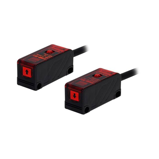
BY Series
Small Emitter/Receiver Synchronizing Type
Features
● Small size: W12×H30×L16mm
● Minimize malfunction by extraneous light
by synchronizing emitter and receiver
● Built-in reverse polarity protection circuit,
output short overcurrent protection circuit
● Fast response speed: Max. 1ms
Please read “Safety Considerations”
in the instruction manual before using.
Specifications
Model
Standard type
Side sensing type
BY500-TDT
BYS500-TDT
Sensing type
Through-beam
Sensing distance
500mm
Sensing target
Opaque materials of min. Ø5mm
Response time
Max. 1ms
Power supply
12-24VDC
Current consumption
Max. 30mA
Light source
Infrared LED (940nm)
Operation mode
Dark ON
Control output
NPN open collector output
● Load voltage: 30VDC ● Load current: max. 100mA ● Residual voltage: max. 1VDC
Protection circuit
Reverse polarity protection circuit, output short overcurrent protection circuit
Indicator
Operation indicator: red LED
Insulation resistance
Over 20MΩ (at 500VDC megger)
Noise immunity
±240V the square wave noise (pulse width: 1㎲) by the noise simulator
Dielectric strength
1,000VAC 50/60Hz for 1 minute
Vibration
1.5mm amplitude at frequency of 10 to 55Hz (for 1 min) in each X, Y, Z direction for 2 hours
Shock
500m/s² (approx. 50G) in each X, Y, Z direction for 3 times
±10% (ripple P-P: max. 10%)
Ambient illumination Sunlight: max. 11,000lx, incandescent lamp: max. 3,000lx (receiving illumination)
EnvironAmbient temperature -10 to 60℃, storage: -25 to 70℃
ment
Ambient humidity
35 to 85%RH, storage: 35 to 85%RH
Protection structure
Material
Cable
IP50 (IEC standard)
Case: acrylonitrile butadiene styrene, sensing part: acrylic, bracket: steel plate cold commercial,
bolt: steel chromium molybdenum, nut: steel chromium molybdenum
Ø4mm, 4-wire, 2m (emitter of through-beam type: Ø4mm, 3-wire, 2m)
(AWG22, core diameter: 0.08mm, number of cores: 60, insulator out diameter: Ø1.25mm)
Accessories
Fixing bracket, M3 bolt: 4, M3 nut: 4
Unit weight
Approx. 150g
※The temperature or humidity mentioned in Environment indicates a non freezing or condensation environment.
A-58
�Small and Amplifier Built-in Type
Feature Data
Parallel shifting characteristic
Angle characteristic
Measuring method
Measuring method
Data
SENSORS
Data
Receiver
ℓ1
L
50
Receiver
40
30
θ
20
0
Emitter
Sensing distance L (cm)
Sensing distance L (cm)
CONTROLLERS
80
40
ℓ1
Left
0
40
ℓ1
Center
L
50
MOTION DEVICES
40
30
20
0
80
Emitter
Right
SOFTWARE
40˚
Control Output Diagram
Main circuit
2.2Ω
Receiver
operation
Load
Max. 100mA
33V
Right
40˚
(A)
Photoelectric
Sensors
(B)
Fiber Optic
Sensors
Operation
Dark ON
mode
(brown) +V
Output short
overcurrent
protection
citcuit
20˚
Center
Operation Mode
Connection
(black) Output
0
Left
Operation angle (θ)
Sensing area (mm)
Photoelectric sensor circuit
20˚
+
-
12-24VDC
(blue) 0V
(white) Synchronous wire:
It is connected with
synchronous wire of the emitter
Received light
(C)
LiDAR
Interrupted light
Operation
indicator
(red LED)
OFF
Transistor
output
OFF
ON
(D)
Door/Area
Sensors
ON
(E)
Vision
Sensors
(F)
Proximity
Sensors
※Applicable models: BY500-TDT2, BYS500-TDT2 (receiver)
※If short-circuit the control output terminal or supply current over the rated specification, normal control signal is not output
due to the output short over current protection circuit.
※Please supply the power to the brown and the blue wires of the emitter and Synchronous wire (white) of the receiver must
be connected with that of the emitter.
Connections
Standard type (dark on)
● BYS500-TDT1
Emitter
(white)
● BY500-TDT2
Sensing
target
+
-
12-24VDC
Emitter
Sensing
target
Receiver
(white)
Synchronous wire (SYNC.)
(brown)
Load
(blue) 0V
● BYS500-TDT2
Receiver
(brown) +V
(white)
(black)
(blue)
Synchronous wire (SYNC.)
Load
(blue) 0V
(white)
(brown)
(brown) +V
+
12-24VDC -
(H)
Rotary
Encoders
(I)
Connectors/
Connector Cables/
Sensor Distribution
Boxes/ Sockets
Side Sensing type (dark on)
● BY500-TDT1
(G)
Pressure
Sensors
(black)
(blue)
※The power of the emitter and the receiver must be supplied from the same power line.
※Synchronous wire (white) of the receiver must be connected with that of the emitter, or it may cause malfunction.
A-59
�BY Series
Dimensions
(unit: mm)
Operation indicator
(red)
4
12
Ø3.6
8
10.5
2.5
15
16
1.2
.
R1
Ø3.2
32
24
10
Optical
axis
30
1
Ø3.6
.8
R1
.6
R1
2.5
10
Operation indicator
(red)
Ø4, 2m
32
24
8 6
4
8 6
19.8
● BY500-TDT
2.5
● BYS500-TDT
5
43
12
12
17
3 10
12
Ø3.2
2.5
R1.
6
1.2
R1.6
24
37.5
Operation indicator
(red)
24
30
2.5
Optical
axis
1
Ø3.2
17
6
16
15
2.5
4.3
.6
R1
Ø3.2
Ø4, 2m
Mounting and Sensitivity Adjustment
1. Supply the power to the sensor, after installing the
Standard type (BY500-TDT)
Side sensing type (BYS500-TDT)
emitter and the receiver facing each other.
2. Set the receiver in the middle of position where the
Adjust Right/Left
Adjust Right/Left
Receiver
operation indicator turns ON adjusting the receiver
Optical
Receiver
Emitter
to the right and the left or up and down.
Optical
axis
axis
3. Fix both units tightly after checking that the unit
Emitter
detects the target.
※If a sensing target is translucent body or smaller
Adjust Up/Down
Adjust Up/Down
than Ø5mm, it might not be detected because the
because light penetrate it.
※ When using photoelectric sensors closely over two units, it may result in malfunction due to mutual interference.
※ When installing the product, tighten the screw with a tightening torque of 0.3N.m.
A-60
�
很抱歉,暂时无法提供与“BYS500-TDT1,2”相匹配的价格&库存,您可以联系我们找货
免费人工找货