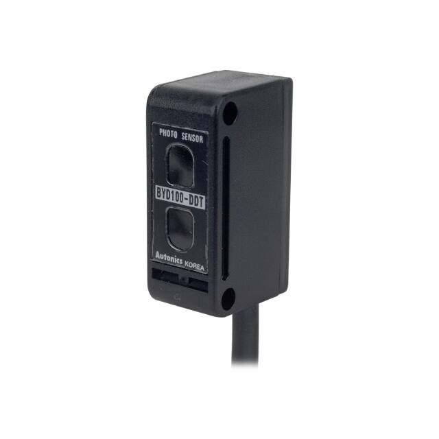
BYD Series
Small Diffuse Reflective and Convergent Reflective Type
SENSORS
Features
● Easy installation by compact size
● Superior detection not affected by color of target
(convergent reflective type)
● Operation indicator is located on the top
(BYD30-DDT-U, BYD50-DDT-U)
● Easy to adjust the response time via Timer function
(off delay time: 0.1 to 2 sec variable)
● �Built-in reverse polarity protection circuit and
output short overcurrent protection circuit
Operation
indicator
CONTROLLERS
MOTION DEVICES
BYD30 (50)-DDT-U
SOFTWARE
Please read “Safety Considerations”
in the instruction manual before using.
Specifications
Model
Sensing type
Sensing distance
Sensing target
BYD30-DDT
BYD50-DDT
BYD30-DDT-U※1
BYD50-DDT-U※1
BYD30-DDT-T※2
BYD50-DDT-T※2
Convergent reflective
10 to 30mm※3
10 to 50mm※3
Translucent, opaque materials
BYD100-DDT
BYD3M-TDT
Diffuse reflective
100mm※3
Through-beam
3m
Opaque materials of Min. Ø6mm
(A)
Photoelectric
Sensors
BYD3M-TDT-P
(B)
Fiber Optic
Sensors
Max. 25% at
sensing distance
Operation: max. 3ms, return: max. 100ms Operation: max. 3ms
Response time
Max. 1ms
(when the timer adjuster is minimum)
Return: max. 100ms
Power supply
12-24VDCᜡ±10% (ripple P-P: max. 10%)
Current consumption
Max. 35mA
Max. 30mA
Light source
Infrared LED
Sensitivity adjustment
Fixed
Sensitivity adjuster Fixed
Operation mode
Light ON fixed
Dark ON (Light ON: option)
NPN or PNP open collector output
NPN open collector output
●Load voltage: max. 30VDCᜡ
●Load voltage: Max. 30VDCᜡ
Control output
●Load current: max. 100mA
●Load current: Max. 50mA
●Residual voltage - NPN: Max.1VDCᜡ,
●Residual voltage: Max. 1V
PNP: Max. 2.5VDC
Protection circuit
Reverse polarity protection circuit, output short overcurrent protection circuit
Built-in timer (off delay)
Timer function
Delay Time: max. 0.1 to 2 sec
(timer adjuster)
Indication
Operation indicator: red LED
Insulation resistance
Over 20MΩ (at 500VDC megger)
Noise immunity
±240V the square wave noise (pulse width: 1㎲) by the noise simulator
Dielectric strength
1,000VAC 50/60Hz for 1minute
Vibration
1.5mm amplitude at frequency of 10 to 55Hz (for 1 min) in each X, Y, Z direction for 2 hours
Shock
500m/s² (approx. 50G) in each X, Y, Z direction for 3 times
Ambient illumination Sunlight: max. 11,000lx, incandescent lamp: max. 3,000lx (receiver illumination)
EnvironAmbient temperature -20 to 65℃, storage: -25 to 70℃
ment
Ambient humidity
35 to 85%RH, storage: 35 to 85%RH
Standard type: IP64 (IEC standards)/
Protection structure
IP50 (IEC standard) IP64 (IEC standard)
※1,※2: IP50 (IEC standards)
Case: acrylonitrile butadiene styrene, sensing part: acrylic, bracket: steel plate cold commercial,
Material
bolt: steel chromium molybdenum, nut: steel chromium molybdenum, sleeve: brass, Ni-plate
Ø3.5mm, 3-wire, 2m (emitter of through-beam type: Ø3.5mm, 2-wire, 2m)
Cable
(AWG24, core diameter: 0.08mm, number of cores: 40, insulator out diameter: Ø1mm)
Accessory
Adjustment screwdriver, fixing bracket A, M3 bolt: 2, M3 nut: 2 Fixing bracket A, M3 bolt: 2, M3 nut: 2
Approval
Weight※4
Approx. 75g (approx. 38g)
Approx. 105g (approx. 80g)
Hysteresis
Max. 10% at sensing distance
※1: Operation indicator is on the top.
※2: OFF delay timer is built-in. (delay time: max. 0.1 to 2sec)
※3: Non-glossy white paper 50×50mm.
※4: The weight includes packaging. The weight in parenthesis is for unit only.
※The temperature or humidity mentioned in Environment indicates a non freezing or condensation environment.
A-61
(C)
LiDAR
(D)
Door/Area
Sensors
(E)
Vision
Sensors
(F)
Proximity
Sensors
(G)
Pressure
Sensors
(H)
Rotary
Encoders
(I)
Connectors/
Connector Cables/
Sensor Distribution
Boxes/ Sockets
�BYD Series
Feature Data
Sensing distance (convergent/diffuse reflective type)
Measuring method BYD30-DDT(-U) / BYD30-DDT-T BYD50-DDT(-U) / BYD50-DDT-T BYD100-DDT
60
50
40
30
20
10
0
Non-glossy white paper
10
5
Left
ℓ1
0
ℓ1
Center
5
10
Sensing distance L (mm)
L
Non-glossy white paper
60
Sensing distance L (mm)
ℓ1
Sensing distance L (mm)
Non-glossy white paper
Standard sensing
target:
Non-glossy white
paper 50×50mm
50
40
30
20
10
0
10
5
Left
Right
Sensing area ℓ1 (mm)
ℓ1
0
ℓ1
Center
5
10
120
100
80
60
40
20
0
4
Right
2
Sensing area ℓ1 (mm)
0
ℓ1
Left
Center
2
4
ℓ1
Right
Sensing area ℓ1 (mm)
Parallel shifting (through-beam type)
Measuring method
BYD3M-TDT
BYD3M-TDT (SLIT)
ℓ1
L
3000
3000
2500
Sensing distance L (mm)
Receiver
Sensing distance L (mm)
Non-glossy white paper
3500
2500
2000
1500
1000
500
0
Emitter
150 100 50 0
Left
2000
SlitØ2.0
1000
SlitØ1.5
500
SlitØ1.0
80 60 40 20 0
ℓ1
ℓ1
Center
SlitØ2.5
1500
0
50 100150
ℓ1
Non-glossy white paper
Left
Right
Sensing area ℓ1 (mm)
20 40 60 80
Center
ℓ1
Right
Sensing area ℓ1 (mm)
※Above characteristic is from 400mm sensing distance to
install transmitted beam type slit (Ø1, Ø1.5, Ø2, Ø2.5).
Sensor angle (through-beam type)
Measuring method BYD3M-TDT
BYD3M-TDT (SLIT)
θ
Emitter
L
Non-glossy white paper
3000
2500
2000
1500
1000
500
0
3500
Sensing distance L (mm)
Receiver
Sensing distance L (mm)
3500
60° 40° 20° 0° 20° 40° 60°
Left
Center
Right
Operation angle (θ)
Non-glossy white paper
2500
2000
SlitØ2.5
1500
SlitØ2.0
1000
SlitØ1.5
500
SlitØ1.0
0
8° 6° 4° 2° 0° 2° 4° 6° 8°
Left
Center
Right
Operation angle (θ)
※Above characteristic is from 400mm sensing distance to
install transmitted beam type slit (Ø1, Ø1.5, Ø2, Ø2.5).
A-62
�Small and Amplifier Built-in Type
Sensing Distance by Color (Convergent Reflective Type)
BYD30-DDT (-U), BYD30-DDT-T
SENSORS
BYD50-DDT (-U), BYD50-DDT-T
CONTROLLERS
33mm
27mm
30mm
20mm
10mm
※Size of sensing target:
Non-glossy paper 50×50mm
Sensing distance
Sensing distance
55mm
50mm
40mm
MOTION DEVICES
45mm
40mm
SOFTWARE
30mm
20mm
10mm
※Size of sensing target:
Non-glossy paper 50×50mm
(A)
Photoelectric
Sensors
1)This model is photoelectric sensor with stable convergent detection type, therefore it is not affected by color or material
within the range of sensing distance as specified in chart.
2)It is able to detect target stably because of small effect from background.
(C)
LiDAR
Operation Mode
● BYD30-DDT (-U), BYD50-DDT (-U), BYD100-DDT
Operation mode
Light ON
(D)
Door/Area
Sensors
● BYD30-DDT-T, BYD50-DDT-T
(E)
Vision
Sensors
Light ON
Receiver operation
Received light
Interrupted light
Received light
Interrupted light
Operation indicator
(red LED)
ON
OFF
ON
OFF
Transistor output
ON
OFF
ON
OFF
Ta
(F)
Proximity
Sensors
t
T
t
T
(G)
Pressure
Sensors
(H)
Rotary
Encoders
(I)
Connectors/
Connector Cables/
Sensor Distribution
Boxes/ Sockets
※T: Setting time by the timer adjuster (0.1 to 2 sec)
※t: Max. 3ms (When the timer adjuster is minimum)
※If Ta is shorter than T, transistor output will be ON.
● BYD3M-TDT, BYD3M-TDT-P
Operation mode
(B)
Fiber Optic
Sensors
Light ON
Dark ON
Receiver operation
Received light
Interrupted light
Received light
Interrupted light
Operation indicator
(red LED)
ON
OFF
ON
OFF
Transistor output
ON
OFF
ON
OFF
※To prevent malfunction, output of units keeps the state of OFF for 0.5sec after power ON.
※Light ON mode is customizable.
A-63
�BYD Series
Control Output Diagram
● BYD3M-TDT2
● BYD3M-TDT2-P
Photoelectric sensor circuit
Connection
Photoelectric sensor circuit
(brown) +V
(brown) +V
+
-
Max. 100mA
3.4Ω
12-24VDC
3.3Ω
Output short
over current
protectio
Main circuit
Main circuit
Load
(black) Output
Output short
over current
protectio
Connection
+
(black) Output
Max. 100mA
12-24VDC
-
Load
(blue) 0V
(blue) 0V
● BYD30-DDT (-U), BYD50-DDT (-U)
● BYD30-DDT-T, BYD50-DDT-Tb
● BYD100-DDT
Photoelectric sensor circuit
Connection
Main circuit
(brown) +V
Load
(black) Output
Max. 50mA
Output short
over current
protectio
+
-
12-24VDC
4.7Ω
(blue) 0V
※�If short-circuit the control output terminal or supply current over the
rated specification, normal control signal is not output due to the
output short over current protection circuit.
Connections
BYD3M-TDT
Emitter
Sensing
target
(brown) +V
12-24VDC
(blue) 0V
A-64
BYD30-DDT (-U), BYD50-DDT (-U),
BYD30-DDT-T, BYD50-DDT-T,
BYD100-DDT
BYD3M-TDT-P
Receiver
(brown) +V
+
-
Load
(black) Output
(blue) 0V
Emitter
Receiver
Sensing
target
(brown) +V
12-24VDC
(blue) 0V
Sensing
target
(brown) +V
+
-
(black) Output
Load
(blue) 0V
(brown) +V
(black) Output
(blue) 0V
Load
+
12-24VDC
-
�Small and Amplifier Built-in Type
Dimensions
(unit: mm)
● Through-beam type
SENSORS
CONTROLLERS
12.4
12.4
3
18
MOTION DEVICES
Optical
axis
Optical
axis
4
32
26
Power indicator (green)
17
17
4
32
SOFTWARE
Ø3.5, 2m
Ø3.5, 2m
4
3.
Ø
2(A)
Photoelectric
Sensors
(B)
Fiber Optic
Sensors
● Convergent/Diffuse reflective type
(C)
LiDAR
Operation indicator (red)
(BYD30(50)-DDT-U Type)
(D)
Door/Area
Sensors
12.4
3
18
(E)
Vision
Sensors
32
26
Built-in timer type:
timer adjuster
Diffuse reflective type:
sensitivity adjuster
Front operation
indicator (red)
4
3.
Ø
2-
(F)
Proximity
Sensors
(G)
Pressure
Sensors
(H)
Rotary
Encoders
(I)
Connectors/
Connector Cables/
Sensor Distribution
Boxes/ Sockets
Ø3.5, 2m
● Bracket A
● Bracket B (sold separately)
25
21.5
12
2-R1.6
10°
8
4-R0.5
9.5
19
4.2
21.5 8.8
45
25
C4
2-R2.2
20
C4
1.5
10°
1.2
10
20
35
13.5
R26
35
6
2-R1.6
6
20
6
4-R2.2
6
R2
4
14
8
A-65
�BYD Series
Mounting and Sensitivity Adjustment
※�When using photoelectric sensors closely over two units,
it may result in malfunction due to mutual interference.
※�When installing the product, tighten the screw with a
tightening torque of 0.5N.m.
Convergent reflective type
1. Supply the power to the sensor after installing the sensor.
Min. 100mm
Sensing
target
Diffuse reflective type
1. �The sensitivity should be adjusted depending on a sensing
target or mounting place.
2. �Set the target at a position to be detected by the beam, then
turn the sensitivity adjuster until position ⓐ where the operation
indicator turns ON from min. position of the sensitivity adjuster.
3. �Take the target out of the sensing area, then turn the sensitivity
adjuster until position ⓑ where the operation indicator turns
ON. If the indicator dose not turn ON, max. position is ⓑ.
4. �Set the sensitivity adjuster at the center of two switching
position ⓐ, ⓑ.
※�The sensing distance indicated on specification chart is for
50×50mm of non-glossy white paper. Be sure that it can be
different by size, surface and gloss of target.
Sensing
target
10 tp 30mm
BYD30-DDT(-U)
BYD30-DDT-T
ⓐ
Adjacent object
(Non-reflective
material must
be applied.)
10 tp 50mm
BYD30-DDT(-U)
BYD30-DDT-T
2. �Install a target at sensing position and adjust the sensor
to right and left or up and down to be at the right angle
against the optical axis and fix it at stable operating
position.
Keep the distance BYD30-DDT, (-T), (-U): 10 to 30mm
BYD50-DDT, (-T), (-U): 10 to 50mm between the
photo-electric sensor and the target.
3. �Adjust the response time up to the optimum status
in case of timer built-in type. Keep the distance min.
100mm between the photoelectric sensor and the
background of the target. It may cause malfunction by
reflection light of the background.
※�The sensing distance indicated in the specification
chart is that of non-glossy white paper in the target size
50×50mm. The sensing distance may be changed by the
size of the target, reflectance of the target.
ⓑ
Min.
Through-beam type
Receiver
Adjust
Right/Left
al
tic
Op
is
ax
Adjust Up/Down
Emitter
Malfunction area
Max.
1. �Supply the power to the photoelectric sensor, after setting the
emitter and the receiver facing each other.
2. �Set the receiver in the middle of the operation range of the
operation indicator by adjusting the receiver and the emitter
right and left, up and down.
3. �After the adjustment, check the stability of operation by putting
the object at the optical axis.
※�If the sensing target is translucent body or smaller than Ø6mm,
it can be missed by sensor because light penetrate it.
Surrounding object
(Mirror)
Stable sensing area
Optimal
position
Accessory (sold separately)
● Slit (Model name: BYD3M-ST)
9.8
※�It may cause malfunction, when surrounding object is
mirror and emitter axis and mirror surface meet at right
angles.
(unit: mm)
19.8
A
Reflective object
Surrounding
object
● �Min. sensing target and Max. sensing distance
by slit Ø
- Attach the slit on receiver and emitter together.
A
Stable sensing area
Malfunction area
※�It may cause malfunction due to reflected light when
reflective material is placed near the optical axis.
A-66
Min. sensing target
Min. sensing distance
Ø1.0
Opaque materials of Min. Ø0.8
500mm
Ø1.5
Opaque materials of Min. Ø1.5
700mm
Ø2.0
Opaque materials of Min. Ø2.0
1200mm
Ø2.5
Opaque materials of Min. Ø2.5
2300mm
※This slit is for BYD3M-TDT (-P) only.
※Total 8 pieces, 2 pieces of each Ø, are packed.
※�This slit is sticker for attachment, please remove the dirt
on lens of the photoelectric sensor before using it.
�