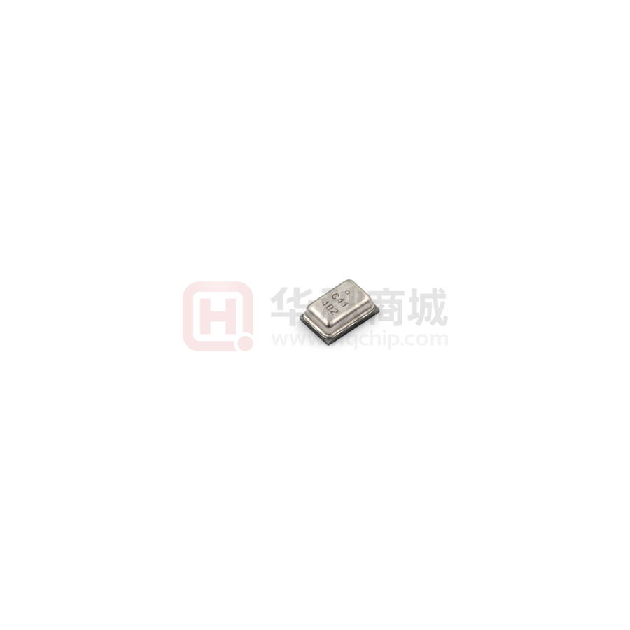
AP2718AB
Analog MEMS Microphone
AP2718AB is an omnidirectional, stable, low power, bottom port, analog MEMS
microphone. The AP2718AB consists of a MEMS acoustic transducer and a low noise
amplifier, which is suitable for cellphones, Bluetooth earphones, headsets, and other
portable electronic devices.
Features:
Flat frequency response
Low current consumption
Omnidirectional
Good uniformity
Standard SMD Reflow
Typical applications:
Cellphones
Bluetooth earphones
Headsets
Laptops
Digital cameras
1. ABSOLUTE MAXIMUM RATINGS
Parameter
VDD to GND
ESD Tolerance (HBM)
ESD Tolerance (CDM)
Storage Temperature
Maximum Rating
Units
-0.3 to +5.5
±2.0
±200
-40 to +105
V
kV
V
°C
Stresses exceeding these “Absolute Maximum Ratings” may cause permanent damage to the device. These
are stress ratings only. Functional operation at these or any other conditions beyond those indicated under
“Acoustic & Electrical Specifications” is not implied. Exposure beyond those indicated under “Acoustic &
Electrical Specifications” for extended periods may affect device reliability.
All Power Semiconductor Co.,Ltd
V1.1
1
�AP2718AB
Analog MEMS Microphone
2. ACOUSTIC & ELECTRICAL SPECIFICATIONS
Test condition: 25±2°C, 45±20% R.H., unless otherwise indicated.
Parameter
Symbol
Directivity
Sensitivity
Signal to Noise
Ratio
Total Harmonic
Distortion
Acoustic
Overload Point
Supply Voltage
Supply Current
S
Min
Typ
Max
Units
Omnidirectional
-39 -38 -37 dBV/Pa
Conditionsi
94 dB SPL @ 1 kHz
94 dB SPL @ 1 kHz,
A-weighted
SNR
63
dB(A)
THD
0.06
%
94 dB SPL @ 1 kHz
AOP
129
dB SPL
10% THD @ 1 kHz
VDD
IDD
1.6
3.6
110
95
V
μA
Power Supply
Rejection Ratio
PSRR
66
dB
Power Supply
Rejection
PSR
-92
dB
Output DC
Impedance
-
220
300
200 mVpp sinewave @ 1
kHz,
VDD = 1.8 V
100 mVpp square wave
@ 217 Hz,
Vdd = 1.8V, A-weighted
Ω
3. FREQUENCY RESPONSE CURVE
All Power Semiconductor Co.,Ltd
V1.1
2
�AP2718AB
Analog MEMS Microphone
4. APPLICATION CIRCUIT
V supply
M EM S m icrophone
Codec
C1
VDD
-
OUTPUT
+
C2
GND
V out
RL
Analog ground
Power supply decoupling:
A 0.1uF ceramic type decoupling capacitor C1is strongly recommended for every
microphone and it should be placed as close to the VDD pad to reduce the noise on
power supply;
The trace connected to each pad of capacitor should be as short as possible, and should
stay on one layer of PCB without via.For the best performance, recommend to place the
capacitor equidistance from power and ground pins of microphone, or slightly closer to
the power pin if space not allowed. System ground should connect to far side of the
capacitor
All Power Semiconductor Co.,Ltd
V1.1
3
�AP2718AB
Analog MEMS Microphone
5. MECHANICAL SPECIFICATIONS
Item
Dimension
Tolerance
Length (L)
Width (W)
Height (H)
Acoustic Port (AP)
2.75
1.85
0.90
Ø0.25
±0.10
±0.10
±0.10
±0.05
Pin #
Description
Pin Name
1
2
3
Power Supply
Output Signal
Ground
VDD
OUT
GND
Dimensions are in millimeters unless otherwise specified.
Tolerance is ±0.05mm unless otherwise specified
All Power Semiconductor Co.,Ltd
V1.1
4
�AP2718AB
Analog MEMS Microphone
6. EXAMPLE OF LAND PATTERN
7. EXAMPLE SOLDER STENCIL PATTERN
Note: Dimensions are in millimeters unless otherwise specified.
All Power Semiconductor Co.,Ltd
V1.1
5
�AP2718AB
Analog MEMS Microphone
8. PACKING & MARKING DETAIL
Note:
1) Dimensions are in mm;
2) Do not push the vacuum suction nozzle alignment the port hole;
3) Tape & Reel Per EIA-481 standard;
4) Label applied to external package and direct to reel;
5) Static voltage
很抱歉,暂时无法提供与“AP2718AB”相匹配的价格&库存,您可以联系我们找货
免费人工找货- 国内价格
- 1+0.58938
- 10+0.56848
- 100+0.50578
- 500+0.49324
