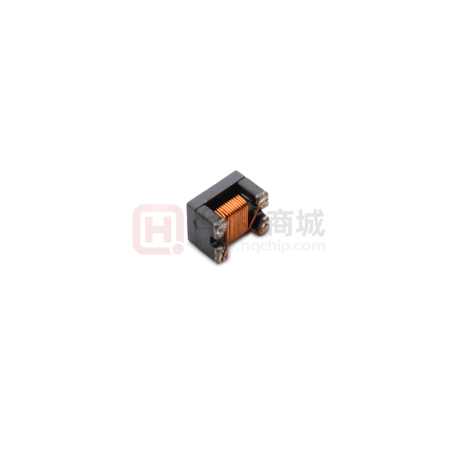
SMW3225S601HTE
PACKING DIMENSIONS (mm)
B
A
Epoxy
C
D
Termination
Wires
E
3225
Dimensions
A
B
C
D
E
F
3.2 ± 0.2
2.5 ± 0.2
2.2 ± 0.2
0.2 ± 0.1
0.80 Typ
0.65 Typ
E
F
F
EXPLANATION OF PART NUMBERS
1
2
3
4
5
6
7
8
9
10
11
12
S
W
(1)
M
3
2
2
5
S
6
0
(3)
1
H
(2)
(1) Product name
(2) Shapes and dimensions
(3) Impedance【 at 100MHz】
601:600Ω
ELECTRICAL CHARACTERISTICS
Z(Ω)
P/N
Common Mode
Impedance
at 100MHz
SMW3225S601HTE
600
DCR (Ω)
[ Max ]
0.25
Rated
current
Idc(A)
[ Max ]
1
Rated
Voltage
Vdc
(V)Typical
50
Insulation
Resistance
IR
(MΩ)Min.
10
Operating temperature : -25 to +85℃
Storage temp. and humidity : -40 to +85℃ ,70%RH max
Typical Heat Rating DC Current would cause an approximately △T of 40℃
Recommended Footprint(mm)
3.7
2.55
0.75
0.9
Rev.01
Page 1 of 5
1.9
www. sunltech.com
�SMW3225S601HTE
PERFORMANCE CURVES
SWM3225S601HTE
10000
Impedance(Ω)
1000
100
10
1
0.1
1
10
100
1000
10000
Frequency(MHz)
Rev.01
Page 2 of 5
www. sunltech.com
�SMW3225S601HTE
Test Equipment
Impedance
Measured by using Agilent 4291A RF Impedance Analyzer.
Measurement terminal
①
④
②
③
DC Resistance
Measurement terminal
Measured by using Chroma 16502 mill ohm meter.
Measurement terminal
①
④
②
③
Measurement terminal
Insulation Resistance
Measured by using Chroma 19073
Measurement voltage : 50v ,Measurement time : 60 sec.
Measurement terminal
Rev.01
①
④
②
③
Page 3 of 5
www. sunltech.com
�SMW3225S601HTE
RECOMMENDED SOLDERING TEMP. GRAPH
10sec. Max.
Preheat 100sec. Max.
255℃
℃
200℃
℃
Natural cooling
150℃
℃
20sec.
60sec. Min.
MECHANICAL RELIABILITY
TEST
Solderability
Specification & Requirement
Method Used
The surface of terminal/pin tested shall
Solder heat proof:
be covered with new solder by 90%
Preheating: 150 ±10℃ 60 seconds
Soldering: 245 ±5℃ for 4 ±1 sec
Solder Heat
Resistance
Components should have not evidence of
Preheating:150℃ 60secs
electrical and mechannical damage
Solder temperature: 260±5℃
Impedance:within ±15% of initial value
Flux:rosin
Dip time:10±0.5 secs
Series No.
F(Kg)
1608
0.5
2012
0.5
3216
1.0
3225
1.0
Terminal strength
Solder a chip to test substrate and then
laterally apply a force in the arrow direction
φ1.0
Test Board
ENDURANCE RELIABILITY
TEST
Specification & Requirement
Impedance change within ± 15% Without
Thermal Shock mechanical damage
Method Used
-65℃, (30 mins) -> room temp. (2 mins) ->
125℃, (30 mins) -> room temp. (2 mins)
50 cycles
Humidity
Resistance
Low Temp.
Storing
High Temp.
Storing
Rev.01
Impedance change within ± 15% Without
Apply IDC current @ 60℃ ambient
mechanical damage
Humidity: 90%
Duration: 168 hrs
Impedance change within ± 15% Without
Storing Temp.
mechanical damage
-40 ±2 ℃ for total 168 +5/-0 hours
Impedance change within ± 15% Without
Storing Temp.
mechanical damage
125 ±2 ℃ for total 168 +5/-0 hours
Page 4 of 5
www. sunltech.com
�SMW3225S601HTE
Reel Dimension & Tape Dimension
A
13
.5
C
B
D
R1
.9
7"x8mm
A(mm)
9.0±0.5
13.5±0.5
R1
5
R0.
120
Type
7”x8mm
7”x12mm
∮ 0.5
0.
5
∮
2 0.5
7"x12mm
B(mm)
60±2
60±2
Size
Ao(mm) Bo(mm) Ko(mm) W(mm)
1608
1.65±0.10
1.00±0.10
1.18±0.10
2012
2.35±0.10
1.50±0.10
3216
3.50±0.10
3225
3.60±0.10
C(mm)
13.5±0.5
13.5±0.5
D(mm)
178±2
178±2
E(mm)
F(mm)
Po(mm) P1(mm) Do(mm)
8.00±0.20
1.75±0.10
3.50±0.05
4.0±0.05
4.0±0.10
none
1.45±0.10
8.00±0.20
1.75±0.10
3.50±0.05
4.0±0.05
4.0±0.10
1.0±0.1
1.88±0.10
2.10±0.10
8.00±0.20
1.75±0.10
3.50±0.05
4.0±0.05
4.0±0.10
1.0±0.1
2.80±0.10
2.20±0.10
8.00±0.20
1.75±0.10
3.50±0.05
4.0±0.05
4.0±0.10
1.0±0.1
Packaging Quantity
Chip Size
8mm/ Reel
Rev.01
3225
1000
Page 5 of 5
www. sunltech.com
�
很抱歉,暂时无法提供与“SMW3225S601HTE”相匹配的价格&库存,您可以联系我们找货
免费人工找货- 国内价格
- 5+1.52874
- 50+1.26036
- 150+1.14534
- 500+1.03032
- 2000+0.86649
- 国内价格
- 5+1.34472
- 50+1.10865
- 150+1.00747
- 国内价格
- 1+1.81010
- 10+1.41520
- 30+1.10890
- 100+1.04260
- 300+0.98560
- 2000+0.94770
