FH35C-13S-0.3SHW(50) 数据手册
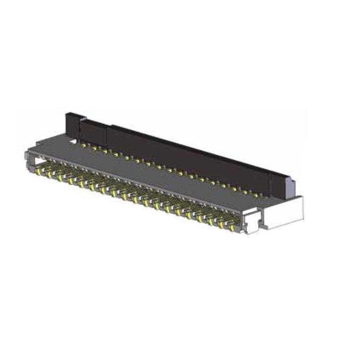
0.3 mm pitch, 0.9 mm height, back flip type dual-sided FPC connector
FH35C Series
%#.bb
●3.2 mm in depth
&'#&
Apr.1.2022 Copyright 2022 HIROSE ELECTRIC CO., LTD. All Rights Reserved.
�bb
�(*�e
^c�
b
(#'b
■Features
1.0.3 mm pitch, Dual-sided connector
This connector utilizes both a top and bottom contact
and provides design flexibility.
●At Time of FPC Insertion
2.Improved FPC retention force achieved through the
use of our proprietary contact structure and a back
flip actuator.
FPC retention force (in the horizontal direction) is about 2.5
times greater than similar products produced by other
companies.
3.Supports high speed transmissions
By utilizing its excellent impedance characteristics, it is
capable of supporting high speed transmissions.
(Differential pairs of identical contacts allows for better
transmission characteristics and eDP (ver1.3) and
compatibility to MIPI(D−PHY) specifications.)
4.Delivered with actuator open
●Lock Completion State
To reduce installation time and costs, the actuator is
delivered in the open position and eliminates the need to
open the actuator before FPC insertion.
5.Easy FPC Insertion
Equipped with tapered guides at the FPC insertions point,
they help to create a smoother FPC insertion operation.
6.Compatible with 0.2mm thick FPC
The FH35C was designed to be used with 0.2 mm FPC.
(Using the appropriate FPC will prevent deformation and
problems that may occur during the insertion and mating
processes.)
7.Bottom side protection
The bottom surface is over-molded and provides added
protection to the contacts (no exposure). This allows the
PCB space under the connector to be used for additional
patterning.
FH35C Differential Impedance
130ps rise time (20-80%)
8.Halogen Free
Chlorine and bromine levels do not exceed the standard
values as defined by IEC 61249-2-21. (Br: 900 ppm or
less, Cl : 900 ppm or less, Br + Cl : 1,500 ppm or less)
9.Compatible with Automatic Mounting
Tape-and-reel packaging is available for use with pick-andplace machines. Connectors are available on 5000 or 500
piece reels. (The outer diameter of an embossed reel is
Ø180mm)
In cases where the application will demand a high level of reliability, such as automotive,
please contact a company representative for further information.
2013.11②
1
�FH35C Series●0.3 mm pitch, 0.9 mm height, back flip type dual-sided FPC connector
■Product Specifications
Operating temperature Range: –55 to
+85°C (Note 2)
Operating temperature Range: 90% or less
of relative humidity
(No dew condensation is allowed)
Current rating: 0.2 A (Note 1)
Voltage rating: AC 30 Vrms
Ratings
With specifications compatible with FPC contacts
Apr.1.2022 Copyright 2022 HIROSE ELECTRIC CO., LTD. All Rights Reserved.
Items
Storage temperature Range: -10 to +50°C
(Note 3)
Storage temperature Range: 90% or less
of relative humidity
(No dew condensation is allowed)
t = 0.2 ± 0.03 gold plating
Specifications
Conditions
1.Insulation Resistance
No less than 50 Mø
Measured at 100 V DC
2.Withstand Voltage
No flashover or breakdown
Conduct 90 V AC for one minute
3.Contact Resistance
100 mø MAX.
* Including FPC conductor resistance
AC 20 mV MAX (1 KHz), 1 mA
4.Mating Cycles
Contact resistance: no more than 100 mø
No breakage, cracks, or loosened parts
10 times
5.Vibration Resistance
No electric outage of 1 µs or greater
Contact resistance: no more than 100 mø
No breakage, cracks, or loosened parts
At the frequency of 10-55 Hz, half amplitude
0.75 mm, and 10 cycles in each of three axial
directions
6.Shock Resistance
No electric outage of 1 µs or greater
Contact resistance: no more than 100 mø
No breakage, cracks, or loosened parts
Acceleration: 981 m/s
Duration: 6 ms, sine half-wave, 3 cycles in each
of the 3 axis each in both directions
7.Humidity Resistance
(Steady State)
Contact resistance: no more than 100 mø
Insulation Resistance: 50 Mø or more
No breakage, cracks, or loosened parts
Left to stand for 96 hours at the temperature of
40°C and the humidity of 90% to 95%
8.Temperature Cycles
Contact resistance: no more than 100 mø
Insulation Resistance: 50 Mø or more
No breakage, cracks, or loosened parts
9.Solder Heat
Resistance
No deformation in appearance or marked
instability of contacts
2
Temperature:-55➝ +15 to+35➝ +85➝ +15 to
+35°C
Time: 30➝ 2 to 3 ➝ 30➝ 2 to 3 minutes
5 cycles with the above conditions
Reflow: According to the Recommended Temperature
Profile
Manual soldering: 350± 10°C for 5± 1 sec.
(Note 1) Use at 70% of the current rating when all pins are energized with the stated current rating.
(Note 2) Temperature rise at the time of electrification is included.
(Note 3) The term “storage” refers to the long-term storage condition of unused products before mounting on the PCB.
The operating temperature and humidity ranges apply to non-energized state after PCB mounting.
(Note 4) The above specifications are representative of this series. Please refer to “drawing for approval” for official individual
agreement.
■Materials
Part
Materials
Treatment
LCP
Gray
Polyamide resin
Black
Contact
Phosphor bronze
Nickel barrier Gold plating
Metal fitting
Phosphor bronze
Pure tin reflow plating
Insulator
UL Regulation
UL94V-0
------
■Product Number Structure
Refer to the chart below when searching for the part number nomenclature.
Please select connectors listed in this catalog when placing orders.
The characteristics and specifications of the products described in this catalog are for reference only.
Please make sure to check the latest delivery specifications before the time of purchase.
FH 35 C − 35S − 0.3 SHW (50)
❶
❷
❸
❹
❶ Series Name: FH
❷ Series No.: 35
❸ C: dual-sided, halogen-free product
❹ Number of contacts : 9 to 51
❺ Contact Pitch: 0.3 mm
2
❺
❻
❼
❻ Contact Form
SHW: SMT horizontal staggered array mount type
❼ Specifications:
(50): standard product (5000 connectors per reel)
(99): 500 connectors per reel
�FH35C Series●0.3 mm pitch, 0.9 mm height, back flip type dual-sided FPC connector
■Connector Dimensions
6¤%#&*
7¤%#&
�%#&'�
�&#+�
%#+¤%#&
�(#(*�
%#(¤%#&
�%#&'�
%#+¤%#&
8¤%#&
9^heaVn�d[�i]Z
cjbWZg�d[�XdgZh
9^heaVnZY
=GH�bVg`
8Vk^in�Cd#
EdaVg^in�bVg`
�%#&*�
�%#+�
�9�
�(�
:¤%#&
�)#'�
�%#(*�
%#.¤%#&
;E8/%#'
�
%é
�&#)*�
�&#&*�
�%#**�
%#)¤%#&
%#%*¤%#&*
(¤%#&*
�&#-�
V�9ZiV^a�YgVl^c\
�.
Apr.1.2022 Copyright 2022 HIROSE ELECTRIC CO., LTD. All Rights Reserved.
V
%#((¤%#&
%#&*¤%#&*
Note 1: The lead coplanarity of contact and reinforcing metal fitting is a MAX of 0.1 mm.
2: This product packaged on tape-and-reel. See the package specification diagram for details.
3: Dimensions may be changed for sink mark prevention due to improvement, etc.
In addition, black dots, etc., may occur in the mold resin but they have no effect on quality.
4: This product is halogen-free.
(Br content: 900 ppm or less; CI content: 900 ppm or less; Br + CL total content: 1,500 ppm or less)
■Connector Dimension Table
Product No.
FH35C-9S-0.3SHW(50)
FH35C-11S-0.3SHW(50)
FH35C-13S-0.3SHW(50)
FH35C-15S-0.3SHW(50)
FH35C-17S-0.3SHW(50)
FH35C-19S-0.3SHW(50)
FH35C-21S-0.3SHW(50)
FH35C-23S-0.3SHW(50)
FH35C-25S-0.3SHW(50)
FH35C-27S-0.3SHW(50)
FH35C-31S-0.3SHW(50)
FH35C-33S-0.3SHW(50)
FH35C-35S-0.3SHW(50)
FH35C-37S-0.3SHW(50)
FH35C-39S-0.3SHW(50)
FH35C-41S-0.3SHW(50)
FH35C-45S-0.3SHW(50)
FH35C-49S-0.3SHW(50)
FH35C-51S-0.3SHW(50)
HRS No.
CL580-2910-5-50
CL580-2917-4-50
CL580-2925-2-50
CL580-2919-0-50
CL580-2916-1-50
CL580-2921-1-50
CL580-2922-4-50
CL580-2911-8-50
CL580-2912-0-50
CL580-2918-7-50
CL580-2923-7-50
CL580-2913-3-50
CL580-2926-5-50
CL580-2914-6-50
CL580-2915-9-50
CL580-2924-0-50
CL580-2909-6-50
–––––––
CL580-2920-9-50
Unit: mm
The number of contacts
9
11
13
15
17
19
21
23
25
27
31
33
35
37
39
41
45
49
51
A
4.3
4.9
5.5
6.1
6.7
7.3
7.9
8.5
9.1
9.7
10.9
11.5
12.1
12.7
13.3
13.9
15.1
16.3
16.9
B
1.8
2.4
3
3.6
4.2
4.8
5.4
6
6.6
7.2
8.4
9
9.6
10.2
10.8
11.4
12.6
13.8
14.4
C
2.4
3
3.6
4.2
4.8
5.4
6
6.6
7.2
7.8
9
9.6
10.2
10.8
11.4
12
13.2
14.4
15
D
3.03
3.63
4.23
4.83
5.43
6.03
6.63
7.23
7.83
8.43
9.63
10.23
10.83
11.43
12.03
12.63
13.83
15.03
15.63
E
3.73
4.33
4.93
5.53
6.13
6.73
7.33
7.93
8.53
9.13
10.33
10.93
11.53
12.13
12.73
13.33
14.53
15.73
16.33
The products with no HRS No. are currently under planning. Please contact our sales representative for questions concerning the number
of contacts.
3
�FH35C Series●0.3 mm pitch, 0.9 mm height, back flip type dual-sided FPC connector
%#(¤%#%'
��c"&�$'��
%#%' M
�8dccZXidg�^bV\Z�¬BdjciZY�hjg[VXZ�
��c &�$'��
%#%' M
%#(¤%#%'
%#+
%#)¤%#%(
%#*¤%#%(
8
M
%#'¤%#%(
%#.*¤%#%(
�%#(*�
�%#'�
%#-¤%#%(
�(#+�
7
%#+
'#&*¤%#%(
%#+*¤%#%(
■Recommended Land Dimensions
�GZXdbbZcYZY�BZiVa�BVh`�I]^X`cZhh/�i�2�%#&�
%#**¤%#%'
Apr.1.2022 Copyright 2022 HIROSE ELECTRIC CO., LTD. All Rights Reserved.
■Recommended Land and Metal Mask Dimensions
7
%#+
%#'(¤%#%'
��c"&�$'��
%#%' N
��c &�$'��
%#'(¤%#%'
%#+
N
8
%#%'
%#(¤%#%'
%#.¤%#%'
N
%#'¤%#%'
%#,¤%#%'
%#+*¤%#%'
�(#+�
'#)¤%#%'
�AVcY�eViiZgc�^bV\Z�
Note 5: 'n' represents the number of contacts.
■Recommended Land and Metal Mask Dimensions
Product No.
FH35C-9S-0.3SHW(50)
FH35C-11S-0.3SHW(50)
FH35C-13S-0.3SHW(50)
FH35C-15S-0.3SHW(50)
FH35C-17S-0.3SHW(50)
FH35C-19S-0.3SHW(50)
FH35C-21S-0.3SHW(50)
FH35C-23S-0.3SHW(50)
FH35C-25S-0.3SHW(50)
FH35C-27S-0.3SHW(50)
FH35C-31S-0.3SHW(50)
FH35C-33S-0.3SHW(50)
FH35C-35S-0.3SHW(50)
FH35C-37S-0.3SHW(50)
FH35C-39S-0.3SHW(50)
FH35C-41S-0.3SHW(50)
FH35C-45S-0.3SHW(50)
FH35C-49S-0.3SHW(50)
FH35C-51S-0.3SHW(50)
4
HRS No.
CL580-2910-5-50
CL580-2917-4-50
CL580-2925-2-50
CL580-2919-0-50
CL580-2916-1-50
CL580-2921-1-50
CL580-2922-4-50
CL580-2911-8-50
CL580-2912-0-50
CL580-2918-7-50
CL580-2923-7-50
CL580-2913-3-50
CL580-2926-5-50
CL580-2914-6-50
CL580-2915-9-50
CL580-2924-0-50
CL580-2909-6-50
–––––––
CL580-2920-9-50
No. of Contacts
9
11
13
15
17
19
21
23
25
27
31
33
35
37
39
41
45
49
51
Unit: mm
B
1.8
2.4
3
3.6
4.2
4.8
5.4
6
6.6
7.2
8.4
9
9.6
10.2
10.8
11.4
12.6
13.8
14.4
C
2.4
3
3.6
4.2
4.8
5.4
6
6.6
7.2
7.8
9
9.6
10.2
10.8
11.4
12
13.2
14.4
15
�FH35C Series●0.3 mm pitch, 0.9 mm height, back flip type dual-sided FPC connector
■Recommended FPC Dimensions
;¤%#%*
%#'¤%#%(
8
O
%#(¤%#%,
��c &�$'��
�G
%#
W
&#,*¤%#(
�GZ[ZgZcXZ�\ZdbZign�
B^hVa^\cbZci�X]ZX`�bVg`
C
Apr.1.2022 Copyright 2022 HIROSE ELECTRIC CO., LTD. All Rights Reserved.
�%#*� �&#'*�
'
'#&¤%#&
6M
%#'¤%#&
B
O
%#,*¤%#&
%#-*¤%#&
%#%'
%#(
'#-*¤%#(��Hi^[[ZcZg�[^ab�
%#%)
%#( "%#%(
%#+
'#'*¤%#&
%#(¤%#%,
%#&¤%#%'
�%#%,�
%#(
�%#'�
��c"&�$'��
%#%)
"%#%(
%#%'
7
%#+¤%#%,
O
%#+¤%#%,
Note 6: FPC should be designed so that the dimension of N is 0.5 mm or more.
■Recommended FPC Dimensions
Product No.
FH35C-9S-0.3SHW(50)
FH35C-11S-0.3SHW(50)
FH35C-13S-0.3SHW(50)
FH35C-15S-0.3SHW(50)
FH35C-17S-0.3SHW(50)
FH35C-19S-0.3SHW(50)
FH35C-21S-0.3SHW(50)
FH35C-23S-0.3SHW(50)
FH35C-25S-0.3SHW(50)
FH35C-27S-0.3SHW(50)
FH35C-31S-0.3SHW(50)
FH35C-33S-0.3SHW(50)
FH35C-35S-0.3SHW(50)
FH35C-37S-0.3SHW(50)
FH35C-39S-0.3SHW(50)
FH35C-41S-0.3SHW(50)
FH35C-45S-0.3SHW(50)
FH35C-49S-0.3SHW(50)
FH35C-51S-0.3SHW(50)
HRS No.
CL580-2910-5-50
CL580-2917-4-50
CL580-2925-2-50
CL580-2919-0-50
CL580-2916-1-50
CL580-2921-1-50
CL580-2922-4-50
CL580-2911-8-50
CL580-2912-0-50
CL580-2918-7-50
CL580-2923-7-50
CL580-2913-3-50
CL580-2926-5-50
CL580-2914-6-50
CL580-2915-9-50
CL580-2924-0-50
CL580-2909-6-50
–––––––
CL580-2920-9-50
Unit: mm
No. of Contacts
9
11
13
15
17
19
21
23
25
27
31
33
35
37
39
41
45
49
51
B
1.8
2.4
3
3.6
4.2
4.8
5.4
6
6.6
7.2
8.4
9
9.6
10.2
10.8
11.4
12.6
13.8
14.4
C
2.4
3
3.6
4.2
4.8
5.4
6
6.6
7.2
7.8
9
9.6
10.2
10.8
11.4
12
13.2
14.4
15
F
3
3.6
4.2
4.8
5.4
6
6.6
7.2
7.8
8.4
9.6
10.2
10.8
11.4
12
12.6
13.8
15
15.6
5
�FH35C Series●0.3 mm pitch, 0.9 mm height, back flip type dual-sided FPC connector
BFPC material composition (Recommended specifications)
1.Single-Sided FPC
Name of material
Cover lay film
Material property
Polyimide 1 mil
(25)
(25)
Cover adhesive
Apr.1.2022 Copyright 2022 HIROSE ELECTRIC CO., LTD. All Rights Reserved.
Thickness (µm)
Surface treatment
Nickel undercoat 1 to 5µm+
Gold plating 0.2µm
Copper foil
Cu
Base adhesive
Heat hardened adhesive
25
Base film
Polyimide
25
Reinforcement material adhesive
Heat hardened adhesive
40
Stiffener film
Polyimide
75
3
35
1 oz
1 mil
3 mil
203
Total
2.Double-Sided FPC
Name of material
Cover lay film
Material property
Polyimide
1 mil
(25)
(25)
Cover adhesive
Surface treatment
Thickness (µm)
Nickel undercoat 1 to 5 µm+
Gold plating 0.2 µm
3
Through-hole copper plating Cu
15
18
Copper foil
Cu
½ oz
Base adhesive
Thermoset adhesive
18
Base film
Polyimide
25
Base adhesive
Thermoset adhesive
Copper foil
Cu
Cover adhesive
Thermoset adhesive
25
Cover lay film
Polyimide
25
Reinforcement material adhesive
Thermoset adhesive
Stiffener film
Polyimide
1 mil
½ oz
18
(18)
1 mil
1 mil
Total
25
25
197
*When using Double-Sided FPC, the copper foil on the back side of the FPC should be eliminated. This is to prevent any unintentional
unlocking due to bent or deformed FPC.
3.Additional notes on FPC
1. The FPC material composition is to be used as a reference example. Please make sure that the thickness of the FPC
mating area is 0.2± 0.03 mm as previously referred to in the product specification section.
2. Please contact the FPC manufacturer for the details on its material composition.
6
�FH35C Series●0.3 mm pitch, 0.9 mm height, back flip type dual-sided FPC connector
BPackaging Specifications
●Emboss Carrier Tape Dimensions
(with tape width of 32 mm or more)
&#,*¤%#&
%
% #&�
)¤%#&
�'�
?¤%#&
=¤%#&


 工商网监
湘ICP备2023018690号
工商网监
湘ICP备2023018690号
