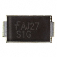
S1A THRU S1M
Reverse Voltage - 50 to 1000 Volts
Forward Current - 1.0 Ampere
SURFACE MOUNT GENERAL RECTIFIER
Features
PINNING
PIN
DESCRIPTION
1
Cathode
2
Anode
The plastic package carries Underwriters Laboratory
Flammability Classification 94V-0
Idea for printed circuit board
Open Junction chip
Low reverse leakage
High forward surge current capability
High temperature soldering guaranteed:
DO-214AC/SMA
2
1
250℃/ 10 seconds at terminals
Mechanical Data
Case : JEDEC DO-214AC/SMA Molded plastic body
Terminals : Solder plated, solderable per MIL-STD-750,Method 2026
Polarity : Polarity symbol marking on body
Mounting Position : Any
Weight : 0.0023 ounce, 0.07 grams
Unipolar
Maximum Ratings And Electrical Characteristics
Ratings at 25 C ambient temperature unless otherwise specified.
Single phase half-wave 60Hz,resistive or inductive load,for capacitive load current derate by 20%.
Parameter
Maximum repetitive peak reverse voltage
Maximum RMS voltage
Maximum DC blocking voltage
Maximum average forward rectified current
at TL=110℃
SYMBOLS
S1A
S1B
S1D
S1G
S1J
S1K
S1M
UNITS
VRRM
VRMS
VDC
50
35
50
100
70
100
200
140
200
400
280
400
600
420
600
800
560
800
1000
700
1000
V
V
V
I(AV)
1.0
A
Peak forward surge current
8.3ms single half sine-wave
superimposed onrated load (JEDEC Method)
IFSM
30
A
Maximum instantaneous forward voltage at 1.0A
VF
IR
1.10
5
50
V
Maximum DC reverse current
at rated DC blocking voltage
CJ
15.0
pF
RJA
75.0
℃/W
-55 to +150
℃
TA=25℃
TA=125℃
Typical junction capacitance (NOTE 1)
Typical thermal resistance (NOTE 2)
Operating junction and storage temperature range TJ,TSTG
Note:1.Measured at 1MHz and applied reverse voltage of 4.0V D.C.
2.P.C.B. mounted with 0.2x0.2”(5.0x5.0mm) copper pad areas
www.tw-gmc.com
1
uA
�S1A THRU S1M
Reverse Voltage - 50 to 1000 Volts
Fig.2 Typical Reverse Characteristics
Instaneous Reverse Current(μ A)
Fig.1 Forward Current Derating Curve
Average Forward Current (A)
1.2
1.0
0.8
0.6
0.4
0.2
Single phase half-wave 60 Hz
resistive or inductive load
0.0
25
75
50
100
125
150
175
100
T J =125°C
10
1.0
T J =25°C
0.1
00
Junction Capacitance ( pF)
TJ =
2 5°
C
00
=1
TJ
=1
25
°C
°C
0.5
TJ
Instaneous Forward Current (A)
1.0
0.9
0.2
1.0
1.1
Peak Forward Surage Current (A)
35
30
25
20
15
10
8.3 ms Single Half Sine Wave
(JEDEC Method)
10
100
Number of Cycles
www.tw-gmc.com
100
120
140
T J =25°C
10
1.0
10
Reverse Voltage (V)
40
1
80
100
0.1
Fig.5 Maximum Non-Repetitive Peak
Forward Surage Current
00
60
1
0.7
Instaneous Forward Voltage (V)
05
40
Fig.4 Typical Junction Capacitance
Fig.3 Typical Forward Characteristic
0.8
20
percent of Rated Peak Reverse Voltage (%)
Case Temperature (°C)
0.1
0.6
Forward Current - 1.0 Ampere
2
100
�S1A THRU S1M
Reverse Voltage - 50 to 1000 Volts
Forward Current - 1.0 Ampere
PACKAGE OUTLINE
Plastic surface mounted package; 2 leads
A
A
SMA
c
a
VM
e
A
HE
g
e
E
A
D
E
HE
c
e
g
max
2.2
4.5
2.7
5.2
0.31
1.6
1.5
min
1.9
4.0
2.3
4.7
0.15
1.3
0.9
max
87
181
106
205
12
63
59
min
75
157
91
185
6
51
35
UNIT
mm
mil
g
e
A
D
The recommended mounting pad size
2.4
(94)
1.8
(71)
1.8
(71)
1.8
(71)
mm
Unit :
(mil)
www.tw-gmc.com
3
a
0.3
12
�
很抱歉,暂时无法提供与“S1G”相匹配的价格&库存,您可以联系我们找货
免费人工找货- 国内价格
- 50+0.06376
- 400+0.05039
- 800+0.04297
- 2000+0.03574
- 国内价格
- 20+0.06956
- 200+0.05498
- 600+0.04688
- 2000+0.03899
- 10000+0.03478
- 20000+0.03251
- 国内价格
- 1+0.09240
- 50+0.04609
- 2000+0.03498