Specifications No.
Messrs.
sc20s15070
DRAFT
( first ・ revised )
Delivery Specifications
Product No
: Quartz Crystal Unit SC-20S
Item code
:
Product form
: 32.768kHz ± 20 × 10-6 / 12.5 pF
Q-SC20S03220C5AAAF
The number of copies : 1 copy
Date of Registrantion
: 31 Mar / '15
Receipt Column
Columm
Note
〈NOTICE〉
1. Advance agreement will be needed before changing any contents of the specification herein.
2. Provided that the information herein is subject to change, only revised pages shall be reissued.
3. When the product described herein includes Regulated Products subject The Wassenaar Arrangement
etc, they may not be exported without authorization from the appropriate governmental authorities.
4. The contents of this specification including all figures and illustrations are proprietary information
(copyright or know-how) of Seiko Instruments Inc. It is strictly prohibited to copy all or part of these
specifications to third parties without permission.
5. In the case that the products described herein are used as part of any devices or equipment which might
influence any one of the human body, human life and property, such as physical exercise equipment,
medical equipment or vehicles, please let us know that.
Seiko Instruments Inc.
Dept. of Issue
Quartz Crystal Division
Sales Section
1-8, Nakase, Mihamaku, Chiba shi, Chiba 261-8507 Japan
SII Crystal Technology Inc.
1110, Hirai cho, Tochigi shi, Tochigi 328-0054 Japan
Dept. of Control
Quality Assurance Section
�1/11
Delivery Specifications
1.Scope
These specifications apply to QUARTZ CRYSTAL RESONATORS ( hereinafter
referred to as RESONATORS ) to be manufactured by Seiko Instruments Inc.
( hereinafter referred to as SII ) to
2.Designation
RESONATORS are designated"SC-20S" ( 32.768 kHz ).
3.Shape and dimensions
As per the SC-20S drawing shown on page 5 .
4.Electrical characteristics
Specified on page 2 through 3 .
5.Shipment and packaging
5.1 ( 3,000 ) pcs are the standard lot size to which the lot number shall be allotted
5.2 The packaging shall conform to the resonator packaging standards.
6.Outgoing inspection
6.1 When mutually agreed, the outgoing inspection shall be conducted as per
the standard on page 4.
6.2 The outgoing inspection slip is not basically affixed to each packaging.
7.Warranty
In the event that any defective RESONATORS or defective lot is found at
incoming inspection at
and that
any defect resulting from failures in process-control at SII after incoming
inspection is found, good RESONATORS shall be supplied to
free of charge as a replacement.
In the event that any trouble or problems rising directly from RESONATORS
occurs, it will be amicably settled between both parties, provided that
warranty shall be done within the score of replacement of good RESONATORS.
8.Revision or abolition of the specifications
Revision or abolition of the specifications shall be made upon mutual consent
between
and SII. If any problem arises,
it shall be amicably settled between both parties.
9.Effectiveness of the specifications
These specifications are effective after receipt of returned copies with your
approved sign.
10.Others
This product is completely Pb-free and Halogen-free.
�2/11
[1] Maximum Rating
Item
1 Storage temperature range
2 Maximum drive level
Symbol
T_stg
DL max.
Rating
-55~+125℃
1.0 μ W max.
Note
Rating
-40~+85℃
0.1 μ W typ.
Note
[2] Recommended Operating Condition
Item
1 Operating temperature range
2 Drive level
Symbol
T_use
DL
[3] Electrical-characteristics
Item
1 Nominal frequency
2 Frequency tolerance
Symbol
f_nom
f_tol
Specification
32.768 kHz
-6
± 20 × 10
3 Load capacitance
CL
12.5 pF
4 Motional resistance
R1
70 kΩ max.
5 Motional capacitance
C1
6 fF typ.
6 Shunt capacitance
C0
1.3 pF typ.
7 Turnover temperature
Ti
25 ± 5℃
8 Parabolic coefficient
B
(-0.03±10%) × 10-6/℃2
f_age
± 3 × 10⁻⁶ /year
IR
500 MΩ min.
9 Frequency aging
10 Insulation resistance
Measurement temperature: 25±2℃
Condition
Measured with ATI 4192A
Impedance analyzer
OSC LEVEL = 0.1V
Measured with ATI 4192A
Impedance analyzer
OSC LEVEL = 0.1V
Measure this coefficient at 5 points
of -40℃、-20℃、25℃、60℃、 85℃
using C-MOS circuit.
25±3℃, First year
Measured with ATI 4329A
Insulation Resistance Meter
Apply DC100V
�3/11
[4] Environment and Mechanical Characteristics
Item
1 High temperature storage 1
High temperature storage 2
2 Low temperature storage
3 High temperature and
Specification
Δ f/f0 = ±10×10
Condition
-6
Δ f/f0 = ±15×10-6
Δ f/f0 = ±10×10
-6
Δ f/f0 = ±10×10
-6
high humidity storage
After storage under 85℃ for 1000 hours,
*1
measure at room temperature.
*3
After storage under 125℃ for 1000 hours,
*1
measure at room temperature.
*3
After storage under -55℃ for 1000 hours,
*1
measure at room temperature.
*3
After storage under +85±2℃ ,
*1
85 % RH for 1000h, measure at room
*3
temperature.
4 Temperature cycle
Δ f/f0 = ±10×10
-6
Measure at room temperature after
*1
100 cycles.
*3
-55℃ ⇔ +125℃ for 30 minutes.
5 Mechanical shock
Δ f/f0 = ±10×10
-6
Measure after 100g-dummy(SII Standard)
drop from 1500mm height on the concrete
at 3 directions for 10 times each.
resistance
6 Vibration resistance
Δ f/f0 = ±10×10-6
Amplitude 1.5mm and 10~60Hz with
*2
*2
cycle time 2~3 minutes in 3 direction
(X,Y, and Z axis) each for 2 h.
7 IR Reflow
8 Shear strength
Δ f/f0 = ±10×10
No peeling-off
-6
Measure after 2 time reflow under
*1
reflow profile specified in page 10
Pressuring force 10N×10±1sec.
*2
according to IEC60068-2-21
9 Peel strength
No peeling-off
Pressuring force 10N×10±1sec.
*2
according to IEC60068-2-21
10 Bending test
No peeling-off
Bending: 3mm×5±1sec.
Thickness of the testing board: 1mm
Note:
1. Each test shall be done independently. (not in series tests)
2. *1: Measure after 24 hours left at room temperature.
3. *2: Measure after 2 hours left at room temperature.
4. *3: Pre conditions
(1) IR Reflow : 2 times
(2) Initial values shall be measured after 24 hours at room temperature.
5. Shift in series resistance after the above tests shall be less than ±20% or less than ±15kΩ .
In case of resistance to IR reflow, shift in series resistance after the above tests shall be less than
±30% or ±20kΩ .
In case of resistance to high temperature storage(±125℃ for 1000 hours), shift in series resistance
after the above tests shall be less than ±40% or ±30kΩ .
*2
�4/11
[5] Precautions
(1) Recommended mounting conditions
Reflow profile
As per reflow profile shown in page 10.
Manual soldering
350℃max. for 4 sec. Max.
(2) Cleaning
The crystal resonator may be destroyed by ultrasonic cleaning.
We don't guarantee the quality of the product with that cleaning method because
such conditions as type of the washing machine, power, time, position in the bath,
and etc. can not be specified.
Please confirm ultrasonic cleaning is not giving any damage to the product
before use when that cleaning method must be used.
[6] Outgoing Inspection Standard
・The outgoing inspection shall be conducted as per the following standard.
・The sampling shall be performed according to the ANSI/ASQC Z1.4-1996.
NO
1
2
3
4
Item
Frequency tolerance
Equivalent series resistance
Outer appearance
Others characteristics
Sampling level
AQL(%)
Ⅰ
1.0
Ⅰ
1.0
Ⅰ
1.5
Periodical quality inspection
�5/11
[7] Dimensions and Marking Layout
1. Out Line Drawing
0.60MAX
S * * * *
#2
#1
1.2±0.1
2-C0.15
1.0 Typ.
Unit = mm
2.05±0.1
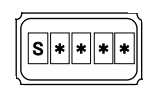
2. Marking
3. Lead Connection
S □ □ □ □
*4 *5
*1 *2 *3
*1
*2
*3
*4, 5
#2
#1
Specification
CL (7pF: B, 9pF: J, 12.5pF: F )
Year of Production (Last Digit of Year)
Week of Production (01~ 52)
4. Recommended PAD Lay-out
#2
1.4
#1
0.7
Unit = mm
0.8
0.7
Please make sure that there is no pattem under SC-20S on the circuit board.
Materials:
Case: Alumina ceramics, Ni-plated, Au-plated
Lead: Kovar material, Ni-plated
�6/11
[8] Taping Specification
1.Drawing of tape dimensions
① Carrier tape : Refer to page 8.
② Taping reel : Refer to page 9.
2.Material
① Carrier tape
② Taping reel
: PC black conductive
: PS conductive
3.Taping method
(1) Taping shall be placed in tapes in such manner as to assure
that marking of the components is visible as per Fig.1
marking
marking
marking
Feed direction for user
Fig. 1
(2) Reel
① On the side of reel there shall be more than 160 mm of "No components".
② The beginning of Carrier Tape shall be bent vertically and hooked on
groove of reel.
(3) Leader
① On the side of leader, there shall be more than 160 mm of "No components"
② The length of Leader shall be over 400 mm.
③ The Length of Stick Tape for Cover Tape shall be about 100 mm and
Stick Tape shall never be detached.
Cover Tape
Carrier Tape
空部
No
Components
リール側
空部
No
Components
製品装着部
Fig. 2
Feed direction for user
リーダー部
Leader
Stick Tape
�7/11
(4) Gap between Carrier Tape and Cover Tape
① Cover Tape protrudes from Carrier Tape by 0.5mm max.
Fig. 3
0.5mm max.
Carrier Tape
Cover Tape
② Holes of Carrier Tape are covered with Cover Tape by 0.75mm max.
Carrier Tape
カバーテープ
Cover Tape
0.75mm max.
Fig. 4
(5) Peel strength
① The method of testing is done as shown below.
② The value of force is at the beginning of desealing.
③ The Cover Tape peel forth shall be 0.1~1.3N at a peel speed of 300±10mm/min.
Fig.5
Cover Tape
165~180°
Direction of Pulling
Carrier Tape
Feed Direction
�8/11
Carrier tape
(1) Conformity with EIA-481
(2) Tolerance : ±0.2
Unit=mm
�9/11
Taping reel
(1) Conformity with EIAJ ET-7200B
(2) Quantity per reel : 3,000pcs./for a reel
11.4
9
Torrance:±0.2mm
Item
Specification
Materials
PS(anti statics)
Inside reel wise W1 9.0+1.0/-0
Outside reel wise W2 11.4±1.0
Unit
mm
mm
Unit = mm
�10/11
[9] Reflow Profile
Pre-heating temperature:+170℃ Pre-heating time:120sec
Heating temperature
:+220℃ Heating time
: 50sec
10±1 sec.
+260 ℃ peak
+250±10 ℃
T
e
m
p
(
℃
)
+220 ℃
+170±10 ℃
50±10 sec.
120±20 sec.
Time(sec)
Note:
(1) The temperature used herein means the temperature on the circuit board.
(2) Reflow is permitted 2 times.
�11/11
[10] Outside Box Packing Specification
Label
1) A label is attached on each reel.
Packed in
an antistatic bag
2) 10 reels are placed in each antistatic polyethylene bag.
Label
【Figure 1】
3) Package
10 reels are placed in each inner box.
4 inner boxes are placed in each shipping carton.
Inner Box
Reel
【Figure 2】
Inner Box x 4
Inner Box
Shipping Carton
【Top View】
4) Storage quantity
Lot = Reel
N = 3,000 pcs /Reel
5) Sample of the label display (Please refer to【 Figure 1 】【 Figure 2 】)
Product bar code
Item bar code
*
Part
SC-20S
: Our company's product name
Lot No.
000001
: Lot No.
Quantity
3,000 pcs
: Quantity
Spec.
32.768kHz
12.5pF/±20×10
: Frequency, CL value, F0 deviation
-6
Quantity Lot.No.bar code Remarks RoHS Compliant
3,000
Pb Free
XXXX
: Environment adaptability, and etc.
6) Storage environment
Please keep the products under the following conditions
﹡ No direct rays
﹡ Temperature condition : +15 to 35 ℃
﹡ Humidity condition
: 25 to 85%RH
7) Storage term
We recommend using within a year of shipment under the environment set in the specification
(Temperature : 15-35℃, Humidity: 25-85%RH) regardless of opening the product or not.
Crystal oscillator doesn't have a lifetime by reason of little performance change caused by
secular variation. Nevertheless, please note that you should confirm the specification of our product
whose storage period expires before use.
�