PESD24VL1BA
Features
■
300W peak pulse power (tp = 8/20μs)
■
Bidirectional configurations
■
Solid-state silicon-avalanche technology
■
Low clamping voltage
■
Low leakage current
■
IEC 61000-4-2 ±30kV contact ±30kV air
■
IEC 61000-4-4 (EFT) 40A (5/50ns)
■
IEC 61000-4-5 (Lightning) 6A (8/20μs)
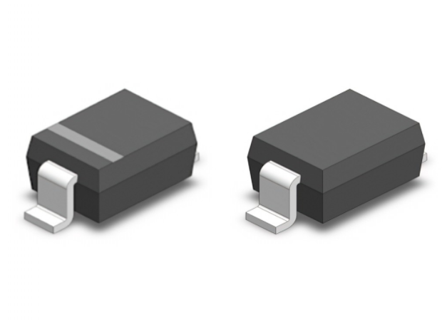
SOD-323
Mechanical Data
Applications
■
Microprocessor based equipment
■
SOD323 package
■
Personal Digital Assistants (PDA’s)
■
Molding compound flammability rating: UL 94V-0
■
Notebooks, Desktops, and Servers
■
Packaging: Tape and Reel
■
Portable Instrumentation
■
RoHS/WEEE Compliant
■
Pagers Peripherals
Absolute Maximum Rating
Rating
Symbol
Value
Units
Peak Pulse Power ( tp =8/20μs)
PPP
300
W
Peak Pulse Current ( tp =8/20μs ) (note1)
Ipp
6
A
VESD
30
30
kV
Lead Soldering Temperature
TL
260
℃
Junction Temperature
TJ
-55 to + 150
℃
Storage Temperature
Tstg
-55 to + 150
℃
ESD per IEC 61000-4-2 (Air)
ESD per IEC 61000-4-2 (Contact)
www.umw-ic.com
1
友台半导体有限公司
�PESD24VL1BA
Electrical Characteristics
Parameter
Symbol
Reverse Stand-Off Voltage
Reverse Breakdown Voltage
Conditions
Min
Typical
VRWM
VBR
IT=1mA
Reverse Leakage Current
IR
VRWM=24V,T=25℃
Clamping Voltage
VC
IPP=6A,tp=8/20μs
Junction Capacitance
Cj
VR = 0V, f = 1MHz
Max
Units
24.0
V
26.7
V
15
0.5
uA
50
V
pF
Electrical Parameters (TA = 25°C unless otherwise noted)
Symbol
Parameter
IPP
Maximum Reverse Peak Pulse Current
VC
Clamping Voltage @ IPP
VRWM
IR
VBR
IT
I
IPP
Working Peak Reverse Voltage
VC VBR VRWM
Maximum Reverse Leakage Current @ VRWM
Breakdown Voltage @ IT
IT
IR
IR
IT
VRWM VBR VC
V
Test Current
IPP
Note:. 8/20μs pulsewaveform.
www.umw-ic.com
2
友台半导体有限公司
�PESD24VL1BA
Typical Characteristics
Figure 2: Power Derating Curve
300w 8/20μs waveform
1
0.1
1
10
100
60
50
50
40
40
30
30
20
20
10
10
0
e-1
50
40
30
td=Ipp/
2
20
0
0 25
2550
50 75
75
100
10
5
www.umw-ic.com
10
15
125
150
150
90
70
60
50
40
Test Test
Waveform
Waveform
Paramters
Paramters
tr=8µs tr=8µs
td=20µstd=20µs
30
20
10
0
0
100
125
Ambient Temperature - TA (℃)
80
Clamping Voltage–VC (V)
80
Ipp
70
60
90
Waveform
Paramters
tr=8µs
td=20µs
90
Percent
80
70
Figure 4: Clamping Voltage vs.Ipp
100
60
90
80
aveform
110
70
90
0
1,000
td – Pulse Duration - µs
Figure3:Pulse
110
100
Clamping Voltage–VC (V)
0.01
0.1
110
100
Percent of Rated Power for Ipp
10
Percent of Rated Power for Ipp
Ppp – Peak Pulse Power - Ppp(KW)
Figure 1: Peak Pulse Power vs. Pulse Time
Time (µs)
20
25
0
30
0
1
2
3
4
5
6
Peak Pulse Current–IPP (A)
3
友台半导体有限公司
�PESD24VL1BA
Outline Drawing – SOD323
DIMENSIONS
SYMBOL
MILLIMETER
MIN
MAX
MIN
MAX
A
1.600
1.800
0.063
0.071
B
0.250
0.350
0.010
0.014
C
2.500
2.700
0.098
D
AF
1.000
0.106
0.039
E
1.200
1.400
0.047
0.055
F
0.080
0.150
0.003
0.006
L
1
INCHES
0.475 REF
0.019REF
L1
0.250
0.400
0.010
0.016
H
0.000
0.100
0.000
0.004
2
Ordering information
Order code
UMW PESD24VL1BA
www.umw-ic.com
Package
Base qty
Delivery mode
SOD323
3000
Tape and reel
4
友台半导体有限公司
�
很抱歉,暂时无法提供与“PESD24VL1BA”相匹配的价格&库存,您可以联系我们找货
免费人工找货- 国内价格
- 20+0.15466
- 200+0.12032
- 600+0.10131
- 3000+0.08003
- 9000+0.07010
- 21000+0.06480
- 国内价格
- 1+0.41051
- 200+0.13721
- 1500+0.08567
- 3000+0.06805
- 国内价格
- 1+0.11218
- 100+0.10428
- 300+0.09638
- 500+0.08848
- 2000+0.08453
- 5000+0.08216
- 国内价格
- 1+0.14470
- 100+0.13440
- 300+0.12400
- 500+0.11370
- 3000+0.10330