Datasheet
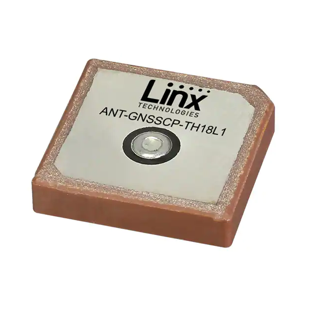
ANT-GNSSCP-TH18L1
Ceramic Patch GNSS Antenna
The GNSSCP-TH18L1 is an 18 mm x 18 mm
square ceramic patch antenna for GPS/GLONASS/
GALILEO/BeiDou global navigation satellite system
(GNSS) operation. It provides excellent gain and
radiation pattern performance supporting solutions
with high location accuracy, rapid satellite signal
reception and lock, and quick time to first fix.
The GNSSCP-TH18L1 offers an extended
temperature range to +105 °C for compliance to
automotive standard AEC-Q200 Grade 2. The
antenna is mounted via attached adhesive patch and
has a solder pin signal connection.
Features
Applications
• Performance at 1567.24 MHz to 1583.60 MHz
― VSWR: ≤ 2.8
― Peak Gain: 5.1 dBi
― Efficiency: 66%
• Directional radiation pattern orthogonal to
antenna surface
• Right-hand circularly polarized (RHCP)
• Extended operation to +105 °C
• AEC-Q200 Grade 2 compliance
• Adhesive mounting to PCB
• Solder pin signal connection
• Global navigation GNSS
― GPS L1
― Galileo E1
― GLONASS I L1
― GLONASS II L1
― Beidou B1-BOC
― Beidou B1-2
― QZSS L1
• Timing solutions
• Automotive location
Ordering Information
Part Number
ANT-GNSSCP-TH18L1
Description
GNSS ceramic patch antenna with pin-type solder connection
Available from Linx Technologies and select distributors and representatives.
�ANT-GNSSCP-TH18L1
Datasheet
Electrical Specifications
GNSSCP-TH18L1
GPS L1, GALILEO E1,
GLONASS II L1, Beidou B1BOC, QZSS L1
Beidou B1-2
GLONASS II L1
Center Frequency
1575.42 MHz
1589.74 MHz
1602 MHz
Frequency Range
1567.24 MHz to 1583.60 MHz 1587.69 MHz to 1591.79 MHz 1593.31 MHz to 1608.68 MHz
VSWR (max)
2.8
3.2
2.9
Peak Gain (dBi)
5.1
2.8
4.0
10 Deg. Elevation (dBi)
2.5
1.7
1.3
Axial Ratio (dB)
12.2
9.6
12.3
Average Gain (dBi)
-2.2
-3.8
-2.3
Efficiency (%)
66
44
65
Polarization
RHCP
Radiation
Omnidirectional
Max Power
8W
Wavelength
1/4-wave
Electrical Type
Ceramic Patch
Impedance
50 Ω
Connection
Pin Type (Through hole)
Operating Temp. Range
-40 °C to +105 °C
Weight
6.0 g (0.21 oz)
Dimensions
18.0 mm x 18.0 mm x 4.0 (0.71 in x 0.71 in x 0.16 in)
ESD Sensitivity
NOT ESD sensitive. As a best practice, Linx may use ESD packaging.
Electrical specifications and plots measured with a 70 mm x 70 mm (2.76 in x 2.76 in) reference ground plane.
Product Dimensions
Figure 1 provides dimensions of the GNSSCP-TH18L1.
18.0 mm
(0.71 in)
4.0 mm
(0.16 in)
TECHNOLOGIES
ANT-GNSSCP-TH18L1
v
Adhesive pad,
NITTO 5015 adhesive
OD 16 mm (0.63 in)
ID 7.5 mm (0.30 in)
Thickness 0.12 mm (0.005 in)
18.0 mm
(0.71 in)
1.7 mm
(0.67 in)
1.8 mm
(0.07 in)
Ø3.0 mm
(0.12 in)
Figure 1. GNSSCP-TH18L1 Antenna Dimensions
2
Pin
Ø0.9 mm
(0.04 in)
�Datasheet
ANT-GNSSCP-TH18L1
VSWR
1609
1601
1602
1592
1593
1590
1587
1584
1575
5
1567
Figure 2 provides the voltage standing wave ratio (VSWR) across the antenna bandwidth. VSWR describes
the power reflected from the antenna back to the radio. A lower VSWR value indicates better antenna
performance at a given frequency. Reflected power is also shown on the right-side vertical axis as a gauge of
the percentage of transmitter power reflected back from the antenna.
VSWR
4
30
3
20
2
10
1
1560
1570
1580
1590
Frequency (MHz)
Reflected Power (%)
40
0
1610
1600
Figure 2. GNSSCP-TH18L1 VSWR
Return Loss
1609
1601
1602
1592
1593
1590
1587
1584
1575
0
1567
Return loss (Figure 3), represents the loss in power at the antenna due to reflected signals. Like VSWR, a
lower return loss value indicates better antenna performance at a given frequency.
-2
Return Loss (dB)
-4
-6
-8
-10
-12
-14
-16
-18
-20
1560
1570
1580
1590
Frequency (MHz)
1600
1610
Figure 3. GNSSCP-TH18L1 Return Loss
3
�ANT-GNSSCP-TH18L1
Datasheet
Peak Gain
1609
1601
1602
1592
1593
1590
1587
1584
1575
10
1567
The peak gain across the antenna bandwidth is shown in Figure 4. Peak gain represents the maximum
antenna input power concentration across 3-dimensional space, and therefore peak performance at a given
frequency, but does not consider any directionality in the gain pattern.
Peak Gain (dBi)
5
0
-5
-10
1560
1570
1580
1590
Frequency (MHz)
1600
1610
Figure 4. GNSSCP-TH18L1 Peak Gain
Average Gain
Average Gain (dBi)
1609
5
0
-5
-10
1560
1570
1580
1590
Frequency (MHz)
Figure 5. GNSSCP-TH18L1 Antenna Average Gain
4
1601
1602
1592
1593
1590
1587
1584
1575
10
1567
Average gain (Figure 5), is the average of all antenna gain in 3-dimensional space at each frequency,
providing an indication of overall performance without expressing antenna directionality.
1600
1610
�Datasheet
ANT-GNSSCP-TH18L1
Axial Ratio
1609
1601
1602
1592
1593
1590
1587
1584
1575
20
1567
Axial ratio provides a measure of the quality of circular polarization of an antenna, the lower the value (in
dB), the better the circular polarization. A circularly polarized antenna field comprises two orthogonal E-field
components.These fields are ideally of equal amplitude, resulting in an axial ratio equal to unity (0 dB). In
practice, no antenna is perfectly circular in polarization, the polarization is elliptical as one field has larger
magnitude. As the axial ratio increases the antenna gain degrades away from the main beam orthogonal to
the antenna surface. The axial ratio for the TH18L1 antenna is shown in Figure 6.
Axial Ratio (dB)
15
10
5
0
1560
1570
1580
1590
Frequency (MHz)
1600
1610
Figure 6. Axial Ratio of the GNSSCP-TH18L1
Radiation Efficiency
1609
1601
1602
1592
1593
1590
1587
1584
1575
100
1567
Radiation efficiency (Figure 7), shows the ratio of power delivered to the antenna relative to the power
radiated at the antenna, expressed as a percentage, where a higher percentage indicates better performance
at a given frequency.
90
80
Efficiency (%)
70
60
50
40
30
20
10
0
1560
1570
1580
1590
1600
Frequency (MHz)
Figure 7. GNSSCP-TH18L1 Antenna Radiation Efficiency
1610
5
�ANT-GNSSCP-TH18L1
Datasheet
Radiation Patterns
Radiation patterns provide information about the directionality and 3-dimensional gain performance of the
antenna by plotting gain at specific frequencies in three orthogonal planes. Antenna radiation patterns are
shown in Figure 8 using polar plots covering 360 degrees. The antenna graphic at the top of the page
provides reference to the plane of the column of plots below it. Note: when viewed with typical PDF viewing
software, zooming into radiation patterns is possible to reveal fine detail.
XZ-Plane Gain
YZ-Plane Gain
XY-Plane Gain
1567.24 MHz to 1583.60 MHz (1576 MHz)
34
35
33
32
31
30
29
28
36 5
0
-5
-10
-15
-20
-25
-30
-35
-40
-45
-50
1
2
3
4
34
5
33
6
32
7
31
8
27
26
30
9
29
10
28
11
27
12
25
21
20
19
18
17
2
3
4
34
5
6
32
7
31
8
30
9
29
10
28
11
27
12
24
XZ-Plane Gain
21
20
19
18
17
1
2
3
4
5
6
7
8
9
10
26
12
25
13
24
15
22
16
36 5
0
-5
-10
-15
-20
-25
-30
-35
-40
-45
-50
11
14
23
35
33
13
15
22
1
25
14
23
36 5
0
-5
-10
-15
-20
-25
-30
-35
-40
-45
-50
26
13
24
35
14
23
16
15
22
21
YZ-Plane Gain
20
19
18
17
16
1567 MHz
1576 MHz
1584 MHz
XY-Plane Gain
1587.69 MHz to 1591.79 MHz (1590 MHz)
34
35
33
32
31
30
29
28
36 5
0
-5
-10
-15
-20
-25
-30
-35
-40
-45
-50
1
2
3
4
34
5
33
6
32
7
31
8
27
26
13
14
23
15
22
21
20
19
18
XZ-Plane Gain
6
30
9
29
10
28
11
27
12
25
24
17
16
35
36 5
0
-5
-10
-15
-20
-25
-30
-35
-40
-45
-50
1
2
3
4
34
5
33
6
32
7
31
8
26
30
9
29
10
28
11
27
12
25
13
24
14
23
15
22
21
20
19
18
17
YZ-Plane Gain
16
35
36 5
0
-5
-10
-15
-20
-25
-30
-35
-40
-45
-50
1
2
3
4
5
6
7
8
9
10
11
26
12
25
13
24
14
23
15
22
21
20
19
18
17
XY-Plane Gain
16
1587 MHz
1590 MHz
1592 MHz
�Datasheet
ANT-GNSSCP-TH18L1
Radiation Patterns
1593.31 MHz to 1608.68 MHz (1601 MHz)
34
35
33
32
31
30
29
28
36 5
0
-5
-10
-15
-20
-25
-30
-35
-40
-45
-50
1
2
3
4
34
5
33
6
32
7
31
8
27
26
30
9
29
10
28
11
27
12
25
13
24
14
23
15
22
21
20
19
18
17
16
XZ-Plane Gain
35
36 5
0
-5
-10
-15
-20
-25
-30
-35
-40
-45
-50
1
2
3
4
34
5
33
6
32
7
31
8
26
30
9
29
10
28
11
27
12
25
13
24
14
23
21
20
19
18
17
36 5
0
-5
-10
-15
-20
-25
-30
-35
-40
-45
-50
1
2
3
4
5
6
7
8
9
10
11
26
12
25
13
24
15
22
35
16
YZ-Plane Gain
14
23
15
22
21
20
19
18
17
16
1593 MHz
1601 MHz
1609 MHz
XY-Plane Gain
Figure 8. GNSSCP-TH18L1 Radiation Patterns
Ground Plane
Ceramic patch antennas are directional in signal transmission and reception orthogonal to the surface plane
of the antenna, and require a ground plane for proper operation. The larger the ground plane, the narrower
the antenna signal beam, and generally, the better the VSWR performance of the antenna. Relatively smaller
ground planes produce wider signal beams. Linx recommends the ground plane size shown in the Electrical
Specifications table to achieve performance similar to that shown in this datasheet. Other ground plane sizes
and antenna mounting locations are possible. The antenna should be mounted at the center of the ground
plane for best performance. Linx offers PCB design reviews to help optimize solution performance.
Antenna Installation
The GNSSCP-TH18L1 attaches to the PCB surface using a double-sided adhesive (0.12 mm thick) which
consists of a flexible pressure sensitive adhesive that adheres to metal, plastic and other non-porous
surfaces. The mounting surface should be clean and free of moisture and oily residues for ideal adhesive
strength. The 4 optional PCB solder pads and their dimensions are provided for use where the adhesive
used to attach the antenna is not adequate to maintain the bond between the antenna and the PCB such as
in installations that are exposed to excessive vibration. To facilitate soldering the adhesive must be removed.
7
�ANT-GNSSCP-TH18L1
ANT-GNSSCP-TH18L1
Datasheet
Recommended Layout
The recommended printed circuit board (PCB) layout for the GNSSCP-TH18L1 is demonstrated by the AEKGNSSCP-TH18L1 evaluation board shown in Figure 9. Contact Linx for availability of PCB layout design files.
The recommended layout includes a matching network, ground plane and PCB transmission line from
the antenna to the matching
network, and to the connector or radio circuitry. The connector used for the
AEK-GNSSCP-TH18L1
www.linxtechnologies.com
evaluation board is optional,
the transmission line may be run directly to the radio if on the same PCB.
Copyright © 2020 Linx Technologies
Linx recommends inclusion of at least a 3-element, surface mount pi matching network of two parallel
capacitors, (C1, C2) and one serial inductor, (L1) in all designs (Figure 10). Surface mount components
should be 0603 size. 0402 size components are also supported. The GNSSCP series antennas, as
designed, do not require matching, but matching may improve end-product antenna performance depending
on the effects of the enclosure, PCB and other electronic components. If no matching is necessary, the serial
element may be populated with a zero-ohm resistor and no components in the two capacitor positions. This
is the configuration of the Linx evaluation board as supplied. Linx believes in wireless made simple® and
offers matching network design support.
PCB Top Side
PCB Bottom Side
70x70mm
ANT-GNSSCP-TH18L1
TECHNOLOGIES
ANT-GNSSCP-TH18L1
Pi matching circuit
C2
ANTENNA
C1
SMA jack
2-Element
(female
socket)
L1
L1
C2
Ground plane
L1 layer
on bottom
for counterpoise
C1
C1
AEK-GNSSCP-TH18L1
www.linxtechnologies.com
Copyright © 2020 Linx Technologies
GND
GND
Figure 9. ANT-GNSSCP-TH18L1 Recommended Layout
3-Element
L1
C1
4-Element
C1
C2
C2
L1
L2
Figure 10. Matching Network Recommendation
C2
L1
C1
8
�Datasheet
ANT-GNSSCP-TH18L1
Recommended PCB Footprint
Figure 11 shows the recommended printed circuit board footprint for the GNSSCP-TH18L1 antenna. The
footprint recommendation should be used in conjunction with the recommended layout configuration shown
in Figure 9.
PCB Bottom Side
Detail View
Scale 2 : 1
PCB Top Side
C2
11.5 mm
(0.45 in)
L1
1.8 mm
(0.07 in)
C2
Through hole
for antenna feed
Ø0.95 mm (0.04 in)
C1
L1
C1
11.5 mm
(0.45 in)
4x PCB Solder Pads
6.5 mm x 6.5 mm
(0.26 in x 0.26 in)
Figure 11. ANT-GNSSCP-TH18L1 Antenna Placement on PCB
Transmission Lines for Embedded Antennas
For most designs, Linx recommends a microstrip transmission line for the GNSSCP-TH18L1 antenna. A
microstrip transmission line is a PCB trace that runs over a ground plane to maintain the characteristic
impedance for optimal signal transfer between the antenna and radio circuitry. Linx designs all antennas with
a characteristic impedance of 50 Ω.
Important practices to observe when designing a transmission line are:
•
Keep all transmission lines to a minimum length for best signal performance.
•
Use RF components that also operate at a 50 Ω impedance.
•
If the radio is not on the same PCB as the antenna, the microstrip should be terminated in a connector,
enabling a shielded cable to complete the antenna connection to the radio.
•
For designs subject to significant electromagnetic interference, a coplanar waveguide transmission line
may be used on the PCB.
The design of a PCB transmission line can be aided by many commercially available software packages
which can calculate the correct transmission line width and gap dimensions based upon the PCB thickness
and dielectric constant used. Linx offers PCB design reviews to help optimize solution performance.
9
�ANT-GNSSCP-TH18L1
Datasheet
Packaging Specifications
The GNSSCP-TH18L1 antennas are packaged in protective plastic trays as shown in Figure 12. Antennas
are packaged 25 per tray, 200 antennas (8 trays) are packed in a carton 10.4 in x 6.1 in x 3.8 in (263 mm x
154 mm x 96 mm). 800 antennas packaged in a shipping box 12.9 in x 11.0 in x 8.6 in (327 mm x 280 mm x
218 mm).
Top View
Front View
Figure 12. Packaging Specifications for the ANT-GNSSCP-TH18L1
10
�Datasheet
VSWR =
10
Return Loss
20
+1
ANT-GNSSCP-TH18L1
Return Loss
Antenna Definitions and Useful Formulas
−1
10
20
VSWR - Voltage Standing Wave Ratio. VSWR is a unitless ratio that describes the power reflected from the
antenna back to the radio. A lower VSWR value indicates better antenna performance at a given frequency.
VSWR is easily derived from Return Loss.
VSWR − 1
Return Loss = −20
log10Loss
Return
+ 1+ 1
10 Return
20 VSWR
Loss
VSWR =
10 Return20 Loss + 1
VSWR = 10
−1
20
Return Loss
− 1 due to reflected signals, measured in
10
Return Loss - Return loss represents the loss
power
at 20
the(G)
antenna
10 log
G in =
db
10
decibels. A lower return loss value indicates better antenna performance at a given frequency. Return Loss is
easily derived from VSWR.
GdBd = GdBi − 2.51dB
VSWR − 1
Return Loss = −20 log10 VSWR − 1
VSWR + 1
Return Loss = −20 log10
VSWR + 1
Return Loss
2
Efficiency (η) - The total power radiated from anVSWR
antenna
by
the input power at the feed point of the
+1
10 − divided
20
1
VSWR =
antenna as a percentage.
(G)
= 10Return
log
Gdb VSWR
10Loss
+ 120
1
(G) −solution
10
Gdb =10
Total Radiated Efficiency - (TRE) The total efficiency
of log
an 10
antenna
comprising the radiation
=
G
−
2.51dB
G
dBiefficiency from the transmitter.
efficiency of the antenna and the transmitteddBd
(forward)
GdBd = GdBi − 2.51dB 2
VSWRVSWR
−1 −1
Loss
TRELoss
= η •= 1
−Return
Return
−20
log
10
11
10 VSWR
20 2 + +
VSWR =VSWR − 1 VSWR + 1
Return Loss
Gain - The ratio of an antenna’s efficiency in a given
direction
power produced by a theoretical
VSWR
− 20
1 2(G) to−the
1
10 +
VSWR
1
lossless (100% efficient) isotropic antenna. The gain of an antenna is almost always expressed in decibels.
VSWR + 1
log10 (G)
Gdb = 10/4
VSWR
VSWR
− 1 2− 1
= −20
GdBi log
−
2.51dB
GdBd =
Return
Loss
TRE = η • 1 − VSWR
10
−
1 2frequency
+1
VSWR
+
1
Peak Gain - The highest antenna gain TRE
across
for aVSWR
given
range. A directional antenna
= all
η •directions
1−
VSWR + 1
will have a very high peak gain compared to average gain.
2
Average Gain - The average gain across all directions
frequency range.
VSWRfor−a1given
log10 (G)
Gdb = 10/4
Maximum Power - The maximum signal power which
VSWRmay
+ 1be applied to an antenna feed point, typically
measured in watts (W).
GdBd = GdBi/4− 2.51dB
Reflected Power - A portion of the forward power reflected back toward the amplifier due to a mismatch at
the antenna port.
VSWR − 1 2
TRE = η • 1 −
VSWR −VSWR
1 2 +1
VSWR + 1
decibel (dB) - A logarithmic unit of measure of the power of an electrical signal.
/4
decibel isotropic (dBi) - A comparative measure in decibels between an antenna under test and an isotropic
VSWR − 1 2
radiator.
TRE = η • 1 −
VSWR
+ 1 between an antenna under test and
decibel relative to a dipole (dBd) - A comparative measure
in decibels
an ideal half-wave dipole.
Dipole - An ideal dipole comprises a straight electrical conductor measuring 1/2 wavelength from end to end
connected at the center to a feed point for the radio. /4
Isotropic Radiator - A theoretical antenna which radiates energy equally in all directions as a perfect sphere.
Omnidirectional - Term describing an antenna radiation pattern that is uniform in all directions. An
isotropic antenna is the theoretical perfect omnidirectional antenna. An ideal dipole antenna has a donutshaped radiation pattern and other practical antenna implementations will have less perfect but generally
omnidirectional radiation patterns which are typically plotted on three axes.
11
�ANT-GNSSCP-TH18L1
Datasheet
Website: http://linxtechnologies.com
Linx Offices: 159 Ort Lane, Merlin, OR, US 97532
Phone:
+1 (541) 471-6256
E-MAIL: info@linxtechnologies.com
Linx Technologies reserves the right to make changes to the product(s) or information contained herein without notice. No liability is assumed as a result of their use
or application. No rights under any patent accompany the sale of any such product(s) or information.
Wireless Made Simple is a registered trademark of Linx Acquisitions LLC. Other product and brand names may be trademarks or registered trademarks of their
respective owners.
Copyright © 2020 Linx Technologies
All Rights Reserved
Doc # DS20213-76ANT Replaces (DS20175-76ANT)
�