Type MK Precision Power Film Radial-Lead Resistors
Page 1 of 2
RoHS Compliant -- MK200 Series and MK700 Series Resistors
Non-Inductive with Expanded Resistance Range — 1 ohm to 100 Megohms
Type MK Precision Power Film Radial-Lead Resistors
provide high density packaging in circuit board applications.
These resistors are available in two compact rectangular
package configurations with standard lead spacings. Type
MK Precision Power Radial-Lead Film Resistors cover the
entire resistance range from 1 ohm to 100 Megohms, with a
standard tolerance of 1%.
Constructed with Caddock's Micronox® resistance films
fired onto a solid ceramic substrate, Type MK Precision Film
Resistors combine all of these outstanding advantages:
• ±1% Resistance Tolerance is Standard - tolerances to
±0.1% are available on special order.
• Operating Temperature - from -40°C to +150°C.
• Power Ratings at +85°C and at +125°C.
• Temperature Coefficient is ≤ 50 ppm/°C from
5 ohms to 5 Megohms and ≤ 80 ppm/°C up to
100 Megohms - referenced to +25°C with the ∆R taken
at -15°C and +105°C.
• Extended Life Stability is typically better than 0.1%
per 1,000 Hours.
• Caddock's Non-Inductive Performance - provides faster
settling times and minimum distortion in all types of higher
frequency circuits.
This combination of performance features in a compact
radial-lead resistor package can simplify engineering,
inventory, and production:
Selecting one compact radiallead resistor package can
simplify board layouts.
With the exceptionally wide
range of resistance values that
are available in each model of
Type MK Precision Power Film
Radial-Lead Resistors, circuits
can now be designed for greater
packaging densities without the need for leaving extra space
where resistor value changes can require larger resistors or
non-uniform lead spacings.
Recommended use:
The Type MK resistors that are shown on this data sheet
are recommended by Caddock for use in commercial and
industrial applications. These RoHS resistors have pure
matte tin (Sn) lead finish optimized for use in commercial and
industrial applications.
Presently, most military applications either prohibit the use of
a matte tin lead finish or are trending toward this prohibition.
Therefore, Caddock does not recommend and does not
support the Type MK Resistors that are shown on this data
sheet for use in military applications.
Any use of this product in a military program, against this
recommended limitation of use, must be completely supported
by the customer program design activity and component
engineering activity based on the complete evaluation and
testing by these activities, there will be no support provided
by Caddock for the military use. In this case, a military
customer drawing must clearly specify the lead material, lead
finish, and the military customer’s responsibility for use.
Using one compact radial-lead resistor package can
speed assembly procedures, simplify procurement, and
simplify inventory.
By reducing the wide variety of sizes and types of
axial-lead resistors to a single compact radial-lead resistor
package with advanced performance ratings, procurement
and inventory can be simplified. The radial leads do not
require additional bending prior to
insertion, and the standard lead
spacing can reduce the time
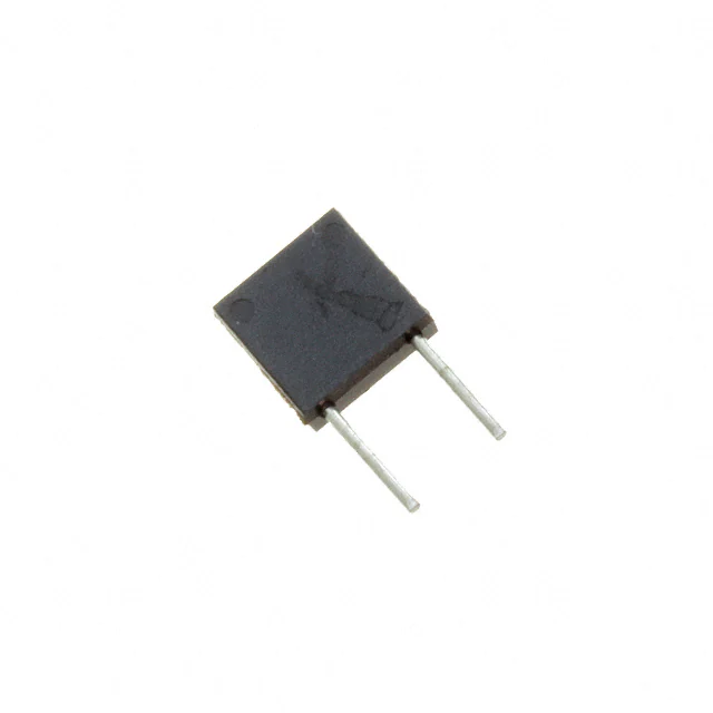
required for assembly. For specific
price and delivery information,
(Resistors shown full size)
contact our Sales Office.
Standard Part Number Includes: Standard resistance value
(listed below), standard tolerance of 1%.
MK227
1.00 Ω
2.00 Ω
4.00 Ω
5.00 Ω
10.0 Ω
20.0 Ω
40.0 Ω
50.0 Ω
100 Ω
200 Ω
400 Ω
500 Ω
1.00 K
2.00 K
4.00 K
5.00 K
10.0 K
20.0 K
40.0 K
50.0 K
100 K
200 K
400 K
500 K
1.00 Meg
2.00 Meg
MK727
4.00
5.00
10.0
20.0
40.0
Meg
Meg
Meg
Meg
Meg
MK232
1.00 Ω
2.00 Ω
4.00 Ω
5.00 Ω
10.0 Ω
20.0 Ω
40.0 Ω
50.0 Ω
100 Ω
200 Ω
400 Ω
500 Ω
1.00 K
2.00
4.00
5.00
10.0
20.0
40.0
50.0
100
200
400
500
1.00
2.00
4.00
5.00
K
K
K
K
K
K
K
K
K
K
K
Meg
Meg
Meg
Meg
MK732
10.0
20.0
40.0
50.0
100
Meg
Meg
Meg
Meg
Meg
Non-Standard Part Number Includes:
Non-standard resistance value and/or non-standard tolerance.
Available in a minimum order quantity of 25 pcs.
Ordering Information:
Model Number
Resistor Value
MK232 - 500K - 1%
Tolerance
�Type MK Precision Power Film Radial-Lead Resistors
Page 2 of 2
Type MK Precision Film Resistors - Low and Standard Resistance Ranges
Model
No.
Resistance
Dimensions
Dieletric
Strength
Low
Min.
Standard
Min.
Standard
Max.
MK227
1Ω
5Ω
2 Meg
0.07%
Fig
1
300
MK232
1Ω
5Ω
5 Meg
0.07%
Fig
2
400
Resistance Tolerance: ±1% is standard.
(Tolerances to ±0.1% available on
values of 30 ohms or higher).
+85°C Maximum Ratings
Max.
1000 hr
Max.
1000 hr
Wattage Working Load Stablity Wattage Working Load Stablity
Voltage ∆R less than
Voltage ∆R less than
±(0.20%
±(0.40%
200
0.20
200
0.50
+ 0.01 ohm)
+ 0.01 ohm)
±(0.20%
±(0.40%
400
0.30
400
0.75
+ 0.01 ohm)
+ 0.01 ohm)
Temperature Coefficient:
Overload/Overvoltage: 5 times rated
power with applied voltage not to
exceed 1.5 times maximum working
voltage for 5 seconds, ∆R ±(0.15 percent
+ 0.01 ohm) max.
Resistance Range
Temp. Coef.
Standard : 5 Ω and above
50 ppm/°C
Low : 1 Ω to 4.99 Ω
200 ppm/°C
Temperature Coefficient referenced to
+25°C, ∆R taken at -15°C and +105°C.
Insulation Resistance: 10,000 Megohms,
minimum.
Operating Temperature: -40°C to +150°C.
+125°C Maximum Ratings
(see Derating Curve)
Load Stability: %∆R is shown in the table
for 1,000 hours at rated voltage not to exceed rated power.
Thermal Shock: MIL-STD-202, Method 107,
Cond. B, except low temperature is -40°C,
∆R ±(0.20 percent + 0.01 ohm) max.
Moisture Resistance: MIL-STD-202,
Method 106, ∆R ±(0.50 percent + 0.01 ohm)
max.
Solderable Leads: Matte Tin Plated Copper.
Measurement Note: Resistance measurement
on low resistance values shall be made at a
point within 0.2 inch (5.08 mm) of the body.
Type MK Precision Film Resistors - Extended Resistance Range
TC
ppm/°C
MK727
MK732
Resistance
Min.
Max.
80
2.01 Meg
40.0 Meg
0.07%
Fig 1
300
80
5.01 Meg
100 Meg
Fig 2
0.07%
400
Resistance Tolerance: ±1%
(consult factory for tighter tolerances).
Overload/Overvoltage: 1.5 times
maximum working voltage for 5 seconds,
∆R 0.50% max.
Operating Temperature: -40°C to +150°C.
Fig 1
Dieletric
Dimensions Strength
Model MK227 and MK727
.095 ±.005
(2.41 ±.13)
.245 ±.010
(6.22 ±.26)
.245 ±.010
(6.22 ±.26)
.150 ±.015
(3.81 ±.38)
.025 ±.002
(.64 ±.05) DIA.,
LEADWIRE OFFSET
.012 (.31)
FROM CENTERLINE
Max.
1000 hr
Max.
1000 hr
Wattage Working Load Stability Wattage Working Load Stability
Voltage ∆R less than
Voltage ∆R less than
Limited
by Max.
Working
Voltage
200
0.20%
400
0.20%
Limited
by Max.
Working
Voltage
200
0.50%
400
0.50%
Temperature Coefficient: See Table for TC
value. TC referenced to +25°C, ∆R taken at
-15°C and +105°C.
Thermal Shock: MIL-STD-202, Method 107,
Cond. B, except low temperature is -40°C,
∆R 0.50% max.
Load Stability: %∆R is shown in the table
for 1,000 hours at rated voltage.
Solderable Leads: Matte Tin Plated Copper.
Insulation Resistance: 10,000 Megohms,
minimum.
Fig 2
Model MK232 and MK732
.095 ±.005
(2.41 ±.13)
.290 ±.010
(7.37 ±.26)
MK227
10.0
1%
.250 ±.050
(6.35 ±1.27)
+125°C Maximum Ratings
(see Derating Curve)
+85°C Maximum Ratings
.250 ±.050
(6.35 ±1.27)
.200 ±.015
(5.08 ±.38)
MK732
100 MEG
1%
.290 ±.010
(7.37 ±.26)
.025 ±.002
(.64 ±.05) DIA.,
LEADWIRE OFFSET
.012 (.31)
FROM CENTERLINE
Moisture Resistance: MIL-STD-202,
Method 106, ∆R 0.50% max.
Derating Curve:
100% @ +85°C
100
% RATED POWER
Model
No.
80
60
40% @ +125°C
40
20
0
25
85
125
150
AMBIENT TEMPERATURE, °C
DIMENSIONS IN INCHES AND (MILLIMETERS)
ELECTRONICS, INC.
e-mail: caddock@caddock.com • web: www.caddock.com
For Caddock Distributors listed by country see caddock.com/contact/dist.html
© 2003-2018 Caddock Electronics, Inc.
Sales and Applications Engineering
17271 North Umpqua Hwy.
Roseburg, Oregon 97470-9422
Phone: (541) 496-0700
Fax: (541) 496-0408
29_IL143.0118
�