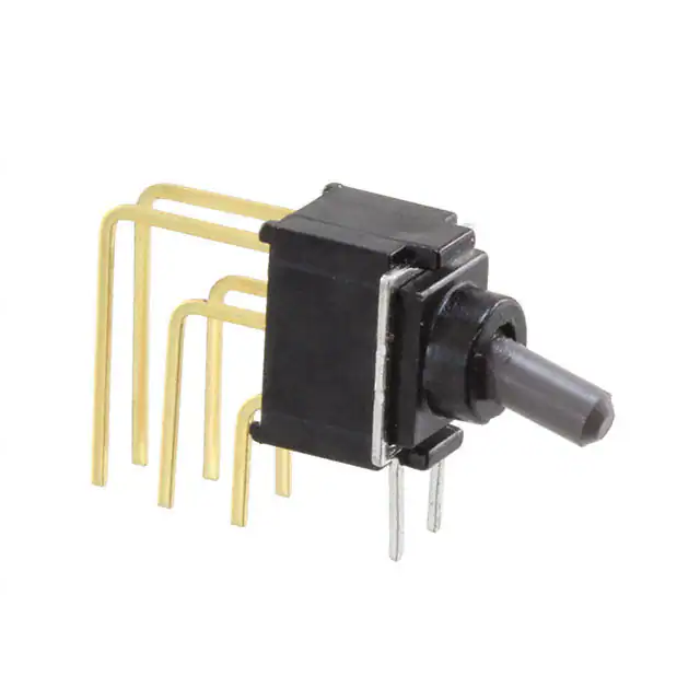
CFT2
■ Terminal Pins : Straight
■ Actuator Color : Gray
Washable
Ultra-Miniature Toggle Switch
RoHS Compliant
■Features
■ Specifications
1. Ultra-miniature toggle switch for high density mounting.
2. Washable.
3. Terminal pin pitch: 2.54 mm.
4. Independent detent mechanism ensures light
operational feel.
5. Clip contact mechanism for long-term contact reliability.
6. Gold-plated contacts.
Rating
Max.
28VDC 0.4VA max.
Min.
1μ A 20mVDC
Initial contact resistance
Dielectric strength
250VAC 1 minute
Insulation resistance
500MΩ min.
Electrical life
Mechanical life
Operating
temperature range
Storage
temperature range
■Part Numbering
CFT2 - 1
Code
Type
T
Toggle
C4
Switching function
Terminal style
1 pole Switching function
Fig.
Terminal style
C
PC Straight
Number of poles
Fig. Number of poles
1
1 pole
E
ONーOFF ー ON
C4
Right angle
G
(ON)ーOFFー(ON)
C6
Vertical mounting
H
ONーOFFー(ON)
0.3
0.5
2.54
C4端子形状
2.54
A
W
Actuator shape
Code Actuator shape
A
Packaging spec
Code Packaging spec
W
Standard
Tray
C6端子形状
3.5
0.3
2.54
ON
−40℃∼+85℃
Terminal style of c4(Style:R/A Terminal) Terminal style of c6(Style:V/M Terminal)
3.2
Terminal
C端子形状style of c(Style:PC Terminal)
ON
ー
−40℃∼+85℃
-
D
(250VDC)
10,000 cycles at max. rating.
50,000 cycles at min. rating.
(D.E.N.P type)
30,000 cycles at min. rating.
(F.G.H.R.S.T type)
D.E.N.P type 50,000 cycles
F.G.H.R.S.T type 30,000 cycles
3
Series Actuator
D
(1.5mA 200μVAC)
100mΩ max.
0.5
0.3
0.5
2.54 2.54
2.54 2.54
2.54
(ON)
:Momentary.
�CFT2
SPDT
4.5
φ4
1.6
3.8
0.5
(4)
30゚
2.54
(1)
Part No.
(5)
2.54
7
Switching
function
Part number marking side
3.2
φ1.9
PC Straight
(14)
5.4
(3)
Key Way
0.5
(6)
MARKING
2.54
2.54
5-φ0.6~0.8
Terminal numbers are not shown on the switch.
−
OFF
OFF
OFF
ON
ON
(ON)
(ON)
Connecting terminals
5−6
−
5−4
3.8
(11.3)
5.4
1.6
−
OFF
OFF
OFF
ON
ON
(ON)
(ON)
−
5−4
Switching
function
Part number marking side
0.5
4.5
φ4
(4)
(5)
30゚
7
ON
ON
(ON)
ON
(Topview)
PC hole Layouts
φ 1.9
Right Angle Terminal
(6)
(6)
0.5
Key Way
MARKING
t=0.3
(2.45)
0.5
5.08
Terminal numbers are not shown on the switch.
※ The above PC hole layout is a view from the switch installation side.
(4)
2.54
5-φ0.6~0.8
(5)
2.54
5.08
☆:Semi-standard products. (ON)
:Momentary.
Part No.
2.54
3.5
3
(5)
2.54
SPDT
(4)
(3)
2.54
2.54
0.3
(1)
CFT2-1DC-AW
CFT2-1EC-AW
☆CFT2-1GC-AW
☆CFT2-1HC-AW
(6)
0.3
(Topview)
PC hole Layouts
CFT2-1DC4-AW
ON
ON
CFT2-1EC4-AW
☆CFT2-1GC4-AW (ON)
ON
☆CFT2-1HC4-AW
Connecting terminals
5−6
�CFT2
SPDT
Vertical mounting terminal
5.6
4.5
3.8
1.6
Switching
function
5.4
Part number marking side
Part No.
7
φ4
30゚
(4)
CFT2-1DC6-AW
ON
ON
CFT2-1EC6-AW
☆CFT2-1GC6-AW (ON)
ON
☆CFT2-1HC6-AW
(5)
(6)
Key Way
(2.5)
0.5
2.54
2.54
0.5
2.54
0.3
5.08
2.54
2.54
Connecting terminals
5-φ0.8
5−6
−
4−5
0.3
φ1.9
5.08
ON
ON
(ON)
(ON)
(6)
Terminal numbers are not shown on the switch.
(5)
(4)
2.54
3
MARKING
0.4
−
OFF
OFF
OFF
(Topview)
PC hole Layouts
※ The above PC hole layout is a view from the switch installation side.
■Soldering Specifications
⑴Manual Soldering
Device:Soldering iron
350℃, Max.; 3 seconds, Max.
⑵Auto Soldering
Device:Jet wave type or dip type
260℃, Max.; 3 to 5 seconds (One time)
Total dip time within 10 sec.
・Pre-heating should be done at temperatures
ranging from 80℃ to 120℃ and within 120 sec.
Pre-heating
■ Flux Cleaning
⑴Solvent : Fluorine or Alcohol type.
⑵Cleaning after soldering should be done after the
PC board is exposed to room temperature (30℃ or
below) for 1 to 2 hours.
⑶Do not use ultrasonic cleaning.
■Packaging Specifications
within 120sec
Plastick Pack
100 pcs/pack
15
KU
SO
SO
231
JI
JI
FU
FU
Soldering
KU
196
⑶When soldering two or more terminals to the common
land, use the solder resist to solder them independently.
(ON)
:Momentary.
☆:Semi-standard products.
�
很抱歉,暂时无法提供与“CFT2-2NC6-AW”相匹配的价格&库存,您可以联系我们找货
免费人工找货- 国内价格
- 1+59.28120
- 200+23.65200
- 500+22.86360
- 1000+22.47480
