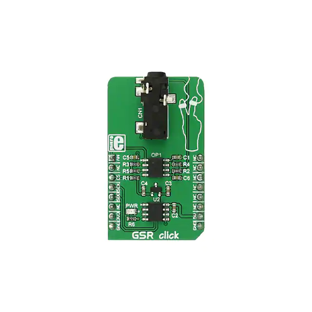
GSR click
PID: MIKROE-2860
Weight: 23 g
GSR click can be used to measure the electrodermal activity (EDA) of the human body, also
known as the galvanic skin response (GSR). EDA is actually the property of the human body that
causes continuous variation in the electrical characteristics of the skin. EDA monitoring is
usually combined with the monitoring of the heart rate, respiratory rate, and blood pressure,
giving a complete insight into some of the parameters of the autonomous nervous systems of the
human body.
EDA measurement is a component of modern polygraph devices, often used as lie detectors.
Recent research reveals that there is more to EDA than it seems, so the studies continue in that
direction. GSR click is ideally suited to be used as the research and experimenting tool, as well
as for building useful test applications based on the EDA response - such as the polygraphs.
�How does it work?
EDA is a common measure of autonomic nervous system activity. Skin conductance is not under
conscious control, it is autonomously controlled by the sympathetic activity and cognitive and
emotional states on a subconscious level. Therefore, the skin electric resistance offers direct
insights into autonomous emotional regulation.
The working principle of the GSR click is based on the voltage divider, composed of two
resistors. One resistor is a fixed resistor 100kΩ (R4) and the second resistor is the human skin,
which acts as the variable resistor. DC Voltage is applied to the skin via one electrode, connected
to the 3.3V rail. The other electrode is used to close the electrical circuit through the skin and
back to the click board. Depending on the resistance of the skin, the voltage at the voltage
divider will vary.
GSR click uses the MCP607, a dual CMOS low-noise OPAMP made by Microchip, as well as
the MCP3201, a 12bit SAR type ADC, made by the same company. The input stage consists of
the aforementioned voltage divider and a frequency limiting capacitor. This signal is then fed to
the first half of the OPAMP, set to a unity gain. It is used to condition the signal before entering
the ADC.
The onboard ADC IC uses the SPI for communication with the MCU. The SPI interface pins are
routed to the appropriate mikroBUS™ pins. MCP3201 ADC also needs a clean and stable
reference voltage, which is provided by the MCP1541, a small, 3-pin specialized reference
voltage IC, from Microchip. The 5V rail is routed to the input of the voltage reference, as well as
the VCC pin of the ADC IC and the OPAMP IC. This means that the click board™ needs both
3.3V and 5V for a proper operation.
The other half of the OPAMP is used as the input buffer for the measured signal and its output is
routed to the AN pin of the mikroBUS™. This signal is analog and can be used for either more
accurate sampling or for applying some other type of measured signal processing.
GSR click has an onboard 3.5 mm jack, used to securely connect the electrodes to the board.
�Specifications
Type
Biomedical
Applications
The GSR click can be used for measurement of the EDA factor of the human body,
allowing the insight in some of the human autonomic nervous system parameters
On-board
modules
MCP607 2.5V to 6.0V Micropower CMOS Op Amp, MCP3201 2.7V 12-Bit A/D Converter
with SPI Serial Interface, MCP1541 2.5V, and 4.096V Voltage References
Key Features
The click features a precise 12bit AD converter so that the measured data can be digitally
processed by the MCU via the SPI, it also outputs buffered analog signal for further
processing (analog or digital)
Interface
Analog,SPI
Input Voltage 3.3V or 5V
Click board
size
M (42.9 x 25.4 mm)
Pinout diagram
This table shows how the pinout on GSR click corresponds to the pinout on the mikroBUS™
socket (the latter shown in the two middle columns).
Pin
Analog
Pin
AN
1
AN
PWM
16
NC
NC
2
RST
INT
15
NC
Chip Select
CS
3
CS
RX
14
NC
SPI Clock
SCK
4
SCK
TX
13
NC
SPI Data Output
SDO
5
MISO
SCL
12
NC
NC
6
MOSI
SDA
11
NC
+3V3
7
3.3V
5V
10
+5V
Power Supply
Notes
Power Supply
�Ground
GND
8
GND
GND
9
GND
Ground
Onboard settings and indicators
Label Name Default
Description
PWR PWR
-
Power LED indicator
CN1
-
3.5mm jack
CN1
Software support
We provide a library for GSR click on our LibStock page, as well as a demo application
(example), developed using MikroElektronika compilers and mikroSDK. The provided click
library is mikroSDK standard compliant. The demo application can run on all the main
MikroElektronika development boards.
Key functions
uint16_t gsr_readMCP3201()- Function reads the value of the ADC converter
Example description
Measure the galvanic skin response by reading voltage level of sensor on the skin.
void applicationTask()
{
voltage = gsr_readMCP3201();
IntToStr(voltage,text);
LOG_write("ADC Value: ", _LOG_TEXT);
LOG_write(text, _LOG_LINE);
Delay_ms(1000);
}
The full application code, and ready to use projects can be found on our LibStock page.
Other MikroElektronika libraries used in the example:
•
•
UART
SPI
�Additional notes and information
Depending on the development board you are using, you may need USB UART click, USB
UART 2 click or RS232 click to connect to your PC, for development systems with no UART to
USB interface available on the board. The terminal available in all MikroElektronika compilers,
or any other terminal application of your choice, can be used to read the message.
mikroSDK
This click board is supported with mikroSDK - MikroElektronika Software Development Kit. To
ensure proper operation of mikroSDK compliant click board demo applications, mikroSDK
should be downloaded from the LibStock and installed for the compiler you are using.
For more information about mikroSDK, visit the official page.
Downloads
mikroBUS™ standard specifications
MCP607 datasheet
MCP3201 datasheet
LibStock: GSR click library
GSR click schematic
LibStock: mikroSDK
GSR click - 2D and 3D files
https://www.mikroe.com/gsr-click 1-15-18
�
很抱歉,暂时无法提供与“MIKROE-2860”相匹配的价格&库存,您可以联系我们找货
免费人工找货