Ordering information
Ripple noise attenuation type for switch mode power supplies(DC)
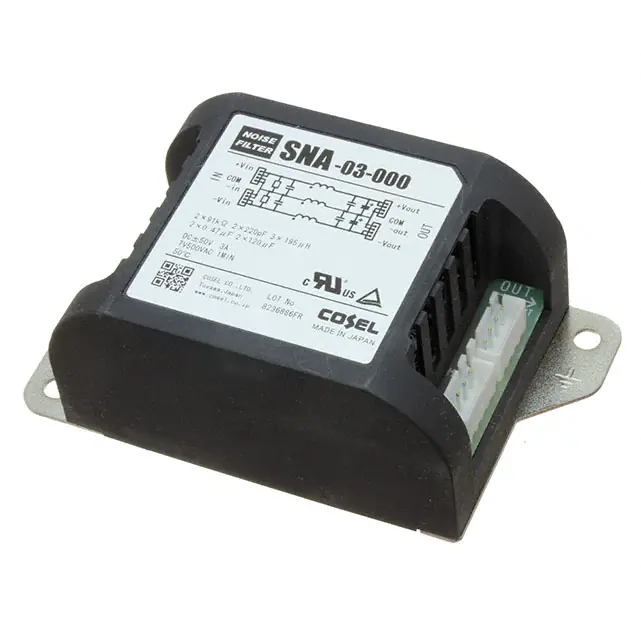
SNA series (1A,3A)
SNA -03 -223
1
2
3
-O
4
1 Model Name
2 Rated Current
3 Line to ground capacitor code:See table 1.1.
R
table1.1 Line to ground capacitor code
Code Line to ground capacitor (nominal value)
000
Not Provided
223
22000pF
4 Options
D :DIN rail installation type
* The dimensions change when the option is set.
Refer to External view.
DIN rail installation type is option
Features of SNA series (1A and 3A)
Ripple noise attenuation type for switch mode power supplies(DC)
-±50 VDC
-Best filter for switch mode power supplies of
analog circuits
(ex. power supply filter for an operational amplifier)
Specifications
No.
SNA-01-223
Items
SNA-03-223
Interface:Connector
1
Rated Voltage DC[V]
±50 (+Vin - COM-in, -Vin - COM-in)
2
Rated Current DC[A]
1
3
Test Voltage (Terminal-Mounting Plate)
500 VAC (Cutoff Current = 100mA), 1minute at room temperature and humidity
3
4
Isolation Resistance (Terminal-Mounting Plate)
500 VDC 50MW min at room temperature and humidity
5
DC resistance
190mW max
6
Operating temperature
-40 to +71C (Refer to Derating Curve)
7
Operating humidity
20 to 95%RH (Non condensing)
8
Storage temperature/humidity
-40 to +75C/20 to 95%RH (Non condensing)
9
Vibration
10 to 55Hz, 19.6m/s2(2G), 3min. Period, 1hour each X, Y and Z axis
10
Impact
196.1m/s2(20G), 11ms Once each X, Y and Z axis
11
Safety agency approvals
UL60950-1, C-UL (CSA60950-1), IEC60950-1
12
Case size (without projection) /Weight
52X35X93 mm [2.05X1.38X3.66 inches] (WXHXD) /130g max (Option : -D refer to external view)
Circuit Diagram
Derating Curve
+Vout
+
100
OUT
Co
COM-out
COM-in
+
Co
-Vin
-Vout
CY
CY : Line to ground capacitor Co : Electrolytic capacitor
80
60
40
20
0
-40
: Mounting Plate
¡Expected life : 10 years
SN-1
Load Factor [%]
CY
+Vin
IN
90mW max
February 04, 2022
-30
-20
-10
0
40
50
Ambient Temperature [C]
60
70 71 80
�SNA series (1A,3A)
External view
Standard Type
2-f4.5
Mounting Hole
[0.18]
CN1
Pin No.
1,2
CN3
4
[1.57]
40 ±0.5
52
[2.05]
CN1
1
CN2
Pin No.
1,2
1
4
4
1
1
CN2
3,4
Function
I/O Connector
CN1~CN4 B4B-XH-AM
Function
-Vout
COM-out
3,4
Mating connector
Terminal
Reel:SXH-001T-P0.6
Bulk:BXH-001T-P0.6
XHP-4
82 ±0.5
(Mfr:J.S.T)
[3.23]
Mounting Plate
COM-out
+Vout
CN4
Pin No.
1,2
-Vin
COM-in
3,4
CN4
Function
1,2
COM-in
+Vin
3,4
4
Name Plate
CN3
Pin No.
Function
Option harness : Refer to Instruction Manual 4
93
[3.66]
¶ Tolerance : ±1 [±0.04]
¶ PCB Material /thickness : CEM3 /1.6mm [0.06 inches]
[1.38]
35
¶ Weight : 130g max
¶ Mounting plate : Iron (surface finishing : nickel plating) t=1.0 [0.04]
¶ Case : PBT
¶ Dimensions in mm, [
]=inches
¶ Keeping drawing current per pin below 2A for CN1 to CN4
1
1
4
4
1
1
CN4
3,4
CN2
Pin No.
1,2
3,4
3,4
XHP-4
Function
-Vout
COM-out
Terminal
Mating connector
Mounting Plate
Reel:SXH-001T-P0.6
Bulk:BXH-001T-P0.6
(Mfr:J.S.T)
[3.31]
Option harness : Refer to Instruction Manual 4
87.5
FG
3,4
Function
Function
COM-out
+Vout
CN4
Pin No.
1,2
-Vin
COM-in
I/O Connector
84
1,2
COM-in
+Vin
CN1~CN4 B4B-XH-AM
M4
CN3
Pin No.
Function
1,2
52
Name Plate
CN2
[0.39]
10
4
CN3
4
[2.05]
CN1
CN1
Pin No.
OUT
IN
DIN rail installation Type
[3.44]
¶ Tolerance : ±1 [±0.04]
¶ Weight : 140g max
35
[1.38]
¶ PCB Material /thickness : CEM3 /1.6mm [0.06 inches]
¶ Mounting plate : Iron (surface finishing : nickel plating) t=1.0 [0.04]
8
[0.31]
¶ Case : PBT
¶ Dimensions in mm, [
]=inches
(9)
[0.35]
¶ Keeping drawing current per pin below 2A for CN1 to CN4
DIN rail
¡Note when installing the EMI/EMC
Filter on a DIN rail.
IN
CN1
CN2
4
1
4
1
When the EMI/EMC Filter is grounded through
the DIN rail, the proper noise attenuation may not
be achieved.
Be sure to connect the FG terminal of the EMI/
EMC Filter body to the earth.
DIN rail
Name Plate
CN3
4
1
4
1
CN4
OUT
February 04, 2022
SN-2
�Ordering information
Ripple noise attenuation type for switch mode power supplies(DC)
SNA series (6A)
SNA -06 -223
1
2
3
-O
4
1 Model Name
2 Rated Current
3 Line to ground capacitor code:See table 1.1.
R
table1.1 Line to ground capacitor code
Code Line to ground capacitor (nominal value)
000
Not Provided
223
22000pF
4 Options
D :DIN rail installation type
T :Terminal block type
DT :Terminal block and DIN rail type
Terminal block type
DIN rail installation type
* The dimensions change when the option is set.
Refer to External view.
DIN rail installation type and Terminal block type are option
Features of SNA series (6A)
Ripple noise attenuation type for switch mode power supplies(DC)
-±50 VDC
-Best filter for switch mode power supplies of
analog circuits
(ex. power supply filter for an operational amplifier)
Specifications
No.
SNA-06-223
Items
Interface:Connector
1
Rated Voltage DC[V]
±50 (+Vin - COM-in, -Vin - COM-in)
2
Rated Current DC[A]
6
3
Test Voltage (Terminal-Mounting Plate)
500 VAC (Cutoff Current = 100mA), 1minute at room temperature and humidity
4
Isolation Resistance (Terminal-Mounting Plate)
500 VDC 50MW min at room temperature and humidity
5
DC resistance
50mW max
6
Operating temperature
-40 to +71C (Refer to Derating Curve)
7
Operating humidity
20 to 95%RH (Non condensing)
8
Storage temperature/humidity
-40 to +75C/20 to 95%RH (Non condensing)
9
Vibration
10 to 55Hz, 19.6m/s2 (2G), 3min. Period, 1hour each X, Y and Z axis
10
Impact
196.1m/s2 (20G), 11ms Once each X, Y and Z axis
11
Safety agency approvals
UL60950-1, C-UL (CSA60950-1), IEC60950-1
12
Case size (without projection) /Weight
52X35X117 mm [2.05X1.38X4.61 inches] (WXHXD) /150g max (Option : -D, -T, -DT refer to external view)
Circuit Diagram
Derating Curve
+Vout
+
IN
100
OUT
Co
COM-out
COM-in
+
Co
-Vin
-Vout
CY
CY : Line to ground capacitor Co : Electrolytic capacitor
80
60
40
20
0
-40
: Mounting Plate
¡Expected life : 10 years
SN-3
Load Factor [%]
CY
+Vin
February 04, 2022
-30
-20
-10
0
40
50
Ambient Temperature [C]
60
70 71 80
�SNA series (6A)
External view
Terminal block Type
40 ±0.5
+Vin
COM-in
-Vin
+Vout
COM-out
-Vout
TB2
Name Plate
CN4
106 ±0.5
106 ±0.5
[4.17]
Mounting
Plate
TB1
6.2
1
CN2
[0.18] Mounting Hole
[0.24]
1
1
4
52
Name Plate
CN3
[1.57]
4
[2.05]
4
1
4
[1.57]
52
[2.05]
40 ±0.5
CN1
2-f4.5
6-M3
7.6
2-f4.5
[0.18] Mounting Hole
[0.3]
Standard Type
117
117
[4.61]
35
35
[1.38]
[1.38]
[4.61]
Terminal cover
[4.17]
Mounting
Plate
CN3
Pin No.
1,2
3,4
CN4
Pin No.
1,2
3,4
CN1
Pin No. Function
1,2
COM-in
3,4
+Vin
CN2
Pin No. Function
1,2
-Vin
COM-in
3,4
Function
COM-out
+Vout
Function
-Vout
COM-out
¶ Tolerance : ±1 [±0.04]
¶ Weight : 150g max
¶ PCB Material /thickness : CEM3 /1.6mm [0.06 inches]
¶ Mounting plate : Iron (surface finishing : nickel plating) t=1.0 [0.04]
¶ Case : PBT
¶ Dimensions in mm, [ ]=inches
¶ Keeping drawing current per pin below 5A for CN1 to CN4
Terminal
I/O Connector Mating connector
CN1~CN4 B4P-VH VHR-4N Reel:SVH-21T-P1.1
Bulk:BVH-21T-P1.1
¶ Tolerance : ±1 [±0.04]
¶ Weight : 160g max
¶ PCB Material /thickness : CEM3 /1.6mm [0.06 inches]
¶ Mounting plate : Iron (surface finishing : nickel plating) t=1.0 [0.04]
¶ Case : PBT
¶ Dimensions in mm, [ ]=inches
¶ Terminal block screw tighting torque M3:0.8N-m (8.5kgf-cm) max
(Mfr:J.S.T)
Option harness : Refer to Instruction Manual 4
DIN rail installation Type
Terminal block type+DIN rail installation Type
108.5
M4
FG
Mounting Plate
112
8
35
Function
-Vout
COM-out
[2.05]
[0.31]
[1.38]
¶ Tolerance : ±1 [±0.04]
¶ Weight : 160g max
¶ PCB Material /thickness : CEM3 / 1.6mm [0.06 inches]
¶ Mounting plate : Iron (surface finishing : nickel plating) t=1.0 [0.04]
¶ Case : PBT
¶ Dimensions in mm, [ ]=inches
¶ Keeping drawing current per pin below 5A for CN1 to CN4
(9)
Function
COM-out
+Vout
7.6
112
DIN rail
[0.35]
8
CN3
Pin No.
1,2
3,4
CN4
Pin No.
1,2
3,4
Terminal cover
[4.41]
[0.31]
35
[1.38]
(9)
[0.35]
CN1
Pin No. Function
1,2
COM-in
3,4
+Vin
CN2
Pin No. Function
1,2
-Vin
COM-in
3,4
Mounting Plate
[4.27]
[4.41]
DIN rail
+Vout
COM-out
-Vout
52
108.5
M4
FG
[4.27]
TB2
OUT
IN
[0.39]
1
CN4
CN2
Name Plate
[0.3]
1
4
TB1
[0.24]
1
+Vin
COM-in
-Vin
10
10
[0.39]
1
4
CN3
4
6.2
Name Plate
[2.05]
4
OUT
CN1
52
IN
6-M3
Terminal
I/O Connector Mating connector
CN1~CN4 B4P-VH VHR-4N Reel:SVH-21T-P1.1
Bulk:BVH-21T-P1.1
¶ Tolerance : ±1 [±0.04]
¶ Weight : 170g max
¶ PCB Material /thickness : CEM3 /1.6mm [0.06 inches]
¶ Mounting plate : Iron (surface finishing : nickel plating) t=1.0 [0.04]
¶ Case : PBT
¶ Dimensions in mm, [ ]=inches
¶ Terminal block screw tighting torque M3:0.8N-m (8.5kgf-cm) max
(Mfr:J.S.T)
Option harness : Refer to Instruction Manual 4
¡Note when installing the EMI/EMC
Filter on a DIN rail.
IN
CN1
CN2
4
1
4
1
When the EMI/EMC Filter is grounded through
the DIN rail, the proper noise attenuation may not
be achieved.
Be sure to connect the FG terminal of the EMI/
EMC Filter body to the earth.
DIN rail
Name Plate
CN3
4
1
4
1
CN4
OUT
February 04, 2022
SN-4
�