AC-DC Power Supplies Enclosed Type
Medical
electric
equipment
Power
Factor
Correction
World wide Safety
Approvals
EMI
Inrush
current
limiting
OCP
OVP
Remote
ON/OFF
Parallel
Operation
1U
PCA-series
PCA300F
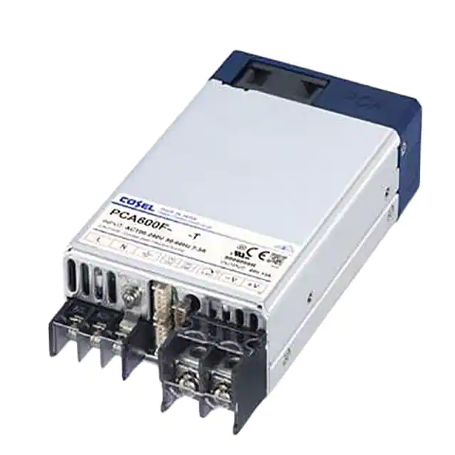
PCA600F
PCA1000F
Feature
Up to 5-year warranty (Refer to Instruction Manual)
Low profile (41mm, 1.61 inch = meet 1U height)
Universal input 85 - 264VAC
(Refer to “Input vltage Derating”)
DC input 88 - 370VDC possible : Excluding PCA1000F and
PCA1500F
(Refer to “Input vltage Derating”)
For medical electric equipment
(ANSI/AAMI ES60601-1, EN60601-1 3rd)
Medical Isolation Grade 2MOPP
With AUX output 12V 0.1A (Voltage adjustable range 5 - 12V)
Constant current function
Output voltage can be adjusted to near 0V (the item 2.6 on
Instruction Manual)
With various alarms
Parallel Operation / N+1 Parallel Redundancy Operation possible
Monitoring function and various setting values can be changed
by communication (the item 2.11 on Instruction Manual)
Safety agency approval
-�UL62368-1, C-UL (CSA62368-1), EN62368-1,
ANSI/AAMI ES60601-1, EN60601-1 3rd
PCA1500F
CE marking
Low Voltage Directive
RoHS Directive
EMI
-�PCA300F, PCA600F
Complies with FCC-B, CISPR32-B, EN55011-B, EN55032-B,
VCCI-B
-�PCA1000F, PCA1500F
Complies with FCC-A, CISPR32-A, EN55011-A, EN55032-A,
VCCI-A
EMS Compliance : �EN61204-3, EN61000-6-2
IEC60601-1-2 (2014), EN60601-1-2 (2015)
EN61000-4-2
EN61000-4-3
EN61000-4-4
EN61000-4-5
EN61000-4-6
EN61000-4-8
EN61000-4-11
April 02, 2021
PCA-1
�AC-DC Power Supplies Enclosed Type
PCA300F
Ordering information
PC
1
A 300 F
2
3
4
Example recommended EMI/EMC filter
NAC-06-472
R
High voltage pulse noise type : NAP series
Low leakage current type : NAM series
Low profile type : EAC series
2MOPP
*�
A higher current rating EMI/EMC filter
may be recommended in view of the
other devices that could be connected
in parallel with the power supply.
-5
5
-O
6
1 �Series name
2 �Single output
3 �Output wattage
4 �Universal input
5 �Output voltage
6 �Optional *7
C : �with Coating
G : �Low leakage current
T : �Terminal Block Style
I : �with PMBus interface
F2 : �Reverse air exhaust type
P3 : �Master-slave Operation
W1 : �Alarm function
For option details, refer to
instruction manual 6.1.
Terminal Block Style
*Make sure necessary tests will be carried out on your end equipment with the power supply installed in accordance with any required EMC/EMI regulations.
MODEL
MAX OUTPUT WATTAGE[W]
DC OUTPUT
PCA300F-5
300
5V 60A
PCA300F-12
324
12V 27A
PCA300F-15
330
15V 22A
PCA300F-24
336
24V 14A
PCA300F-32
320
32V 10A
PCA300F-48
336
48V 7A
SPECIFICATIONS
MODEL
[VAC]
[VDC]
ACIN 100V
ACIN 230V
VOLTAGE
CURRENT[A]
*1
FREQUENCY[Hz]
(Io=50%)
(Io=100%)
EFFICIENCY[%]
INPUT
(Io=50%)
ACIN 230V
(Io=100%)
ACIN 100V
POWER FACTOR
ACIN 230V
ACIN 100V*2
INRUSH CURRENT[A]
ACIN 230V*2
LEAKAGE CURRENT[mA]
VOLTAGE[V]
CURRENT[A]
LINE REGULATION[mV]
LOAD REGULATION[mV]
0 to +50C *3*4
RIPPLE[mVp-p]
-20 to 0C *3
0 to +50C *3*4
RIPPLE NOISE[mVp-p]
OUTPUT
-20 to 0C *3
0 to +50C *4
TEMPERATURE REGULATION[mV]
-20 to +50C *4
*5
DRIFT[mV]
START-UP TIME[ms]
HOLD-UP TIME[ms]
OUTPUT VOLTAGE ADJUSTMENT RANGE[V]
OUTPUT VOLTAGE SETTING[V]
OVERCURRENT PROTECTION
OVERVOLTAGE PROTECTION[V]
PROTECTION REMOTE SENSING
CIRCUIT AND REMOTE ON/OFF (RC)
OTHERS
DC_OK LAMP
ALARM LAMP
COMMUNICATION FUNCTION
INPUT-OUTPUT
INPUT-FG
ISOLATION
OUTPUT-FG
OUTPUT - AUX-RC-PG-INFO-DS-ADDR0-ADDR1-ADDR2
OPERATING TEMP.,HUMIDITY.AND ALTITUDE
STORAGE TEMP.,HUMIDITY.AND ALTITUDE
ENVIRONMENT
VIBRATION
IMPACT
ACIN 100V
SAFETY
AND NOISE
REGULATIONS
PCA-2
AGENCY APPROVALS
CONDUCTED NOISE
HARMONIC ATTENUATOR
*6
PCA300F-5
PCA300F-12
PCA300F-15
PCA300F-24
PCA300F-32
PCA300F-48
85 - 264 1f
88 - 370
3.8typ
1.6typ
50/60 (45 - 66)
86typ
87typ
87typ
88typ
88typ
88typ
87typ
88typ
88typ
89typ
89typ
89typ
87typ
88typ
88typ
89typ
89typ
89typ
89typ
90typ
90typ
91typ
91typ
91typ
0.98typ (Io=100%)
0.95typ (Io=100%)
20/40 typ (Io=100%) (Primary inrush current / Secondary inrush current) (More than 3 sec. to re-start)
40/40 typ (Io=100%) (Primary inrush current / Secondary inrush current) (More than 3 sec. to re-start)
0.5max (ACIN 240V 60Hz, Io=100%, According to IEC60601-1)
5
12
15
24
32
48
60
27
22
14
10
7
20max
48max
60max
96max
128max
192max
40max
100max
120max
150max
150max
480max
160max
240max
240max
240max
320max
480max
280max
320max
320max
320max
420max
640max
240max
300max
300max
300max
400max
600max
320max
360max
360max
360max
480max
720max
50max
120max
150max
240max
320max
480max
75max
180max
180max
290max
400max
600max
20max
48max
60max
96max
128max
192max
700typ (ACIN 100/230V Io=100%)
20typ (ACIN 230V Io=80%) / 16typ (ACIN 230V Io=100%)
3.00 to 6.00
7.20 to 14.40
9.00 to 18.00
14.40 to 28.80
19.20 to 38.40
28.80 to 57.60
5.00 to 5.05
12.00 to 12.12
15.00 to 15.15
24.00 to 24.24
32.00 to 32.32
48.00 to 48.48
Works over 105% of rating (Recovers automatically, Hiccup overcurrent)
6.25 to 7.00
15.00 to 16.80
18.75 to 21.00
30.00 to 33.60
40.00 to 44.80
60.00 to 67.20
Provided
Provided
LED (Blue)
LED (Orange)
Provided (Extended UART)
AC4,000V 1minute, Cutoff current = 10mA, DC500V 50MΩ min (At Room Temperature) 2MOPP
AC2,000V 1minute, Cutoff current = 10mA, DC500V 50MΩ min (At Room Temperature) 1MOPP
AC500V 1minute, Cutoff current = 100mA, DC500V 50MΩ min (At Room Temperature)
AC500V 1minute, Cutoff current = 100mA, DC500V 50MΩ min (At Room Temperature)
-20 to +70C, 20 - 90%RH (Non condensing)
-20 to +75C, 20 - 90%RH (Non condensing)
10 - 55Hz 19.6m/s2 (2G) 3minutes period, 60minutes each along X, Y and Z axis
196.1m/s2 (20G) 11ms, once each X, Y and Z axis
UL62368-1, EN62368-1, C-UL (equivalent to CAN/CSA-C22.2 No.62368-1), ANSI/AAMI ES60601-1, EN60601-1 3rd,
C-UL (equivalent to CAN/CSA-C22.2 No.60601-1), Complies with IEC60601-1-2 4th Ed.
Complies with FCC Part15 classB, VCCI-B, CISPR32-B, EN55011-B, EN55032-B
Complies with IEC61000-3-2 (class A)
April 02, 2021
�PCA300F
SPECIFICATIONS
CASE SIZE/WEIGHT
COOLING METHOD
OTHERS
89X41X152mm [3.50X1.61X5.98 inches] (without terminal block and screw) (WXHXD) / 840g max
Forced cooling (internal fan)
*1 �DC input safety agency approvals deleted.
*2 �The value is primary surge. The current of input surge to a built-in EMI/EMS Filter(0.2ms or
less) is excluded.
*3 �Measured by 20MHz oscilloscope or Ripple-Noise meter (equivalent to KEISOKUGIKEN:RM103). Please refer to the instruction manual 1.2.
*4 �5V output product, the maximum temperature of 40C.
*5 �Drift is the change in DC output for an eight hours period after a half-hour warm-up at 25C.
*6 �Please contact us about another class.
*7 �The listed options may affect the published standard specifications. Please contact us for
detailed product specifications and safety approvals.
* �A sound may occur from power supply at pulse loading.
Features
- �Low profile (41mm, 1.61 inch = meet 1U height)
- �Universal input 85 - 264VAC
- �DC input 88 - 370VDC possible
- �For medical electric equipment (ANSI/AAMI ES60601-1,
EN60601-1 3rd, IEC60601-1-2 4th Ed.)
- �Medical Isolation Grade 2MOPP
- �With AUX output 12V 0.1A (Voltage adjustable range 5 12V)
- �Constant current function
- �Output voltage can be adjusted to near 0V
(the item 2.6 on Instruction Manual)
- �With various alarms
- �Parallel Operation / N+1 Parallel Redundancy Operation
possible
- �Monitoring function and various setting values can be
changed by communication
(the item 2.11 on Instruction Manual)
- �Complies with SEMI F47 (the item 2.1 on Instruction Manual)
Block diagram
AC(L)
AC IN
85 - 264V
FUSE
250V10A
AC(N)
NOISE
FILTER
INRUSH
CURRENT
LIMIT
RECTIFIER
SWITCHING
DEVICE
RECTIFIER
AND
FILTER
250V10A
FG
CURRENT
SENSING
CONTROL
TRANSFORMER
FAN
INTERNAL
REGULATOR
AUX
(12V0.1A)
TRANSFORMER
REGULATOR
RECTIFIER
AND
FILTER
INVERTER
±S
(Remote sensing)
Photocoupler
OVER
VOLTAGE
PROTECTION
CURRENT
SENSING
DC OUT
RC
(Remote ON/OFF)
PG
(Alarm)
CB
(Current balance)
Photocoupler
CONTROL
DS
(Data Shared signal)
CONTROL
THERMAL
PROTECTION
Photocoupler
VTRM
(Adjustment of output voltage)
ITRM
(Adjustment of output current)
INFO
(Extended UART)
Photocoupler
April 02, 2021
PCA-3
�PCA300F
External view
2-M4 (Depth:6mm max)
Mounting Hole
7
7
[0.28]
[0.28]
[0.28]
7
14.5
16
[0.63]
20.5
[0.81]
14.5
[0.57]
[0.57]
13
[0.51]
39
[2.99]
Name plate
2-M4 (Depth:6mm max)
Mounting Hole (Bottom side)
44.5
[1.75]
M4
89
[3.50]
[0.34]
8.6
[2.31]
58.75
64.5
[2.54]
57.5
10
[0.79]
76±0.5
M4
CN1
[0.10]
2.5
14.5
[0.57]
32.5
35
[1.38]
4
[0.16]
[1.28]
24
[0.94]
87±0.5
[3.43]
152
[5.98]
2-M3
2-M4 (Depth:6mm max)
Mounting Hole
2-f8.5
PCA-4
20.5
[0.16]
4
¶ Tolerance : ±1 [±0.04]
¶ Weight : 840g max
¶ PCB Material / thickness : FR-4 / 1.6mm [0.06]
¶ Chassis Material : Aluminum
¶ Fan cover Material : PBT
¶ Dimensions in mm, [ ] = inches
¶ Mounting torque : 1.2N-m max
¶ Input and output terminal screw tightening torque
M3 0.6N-m max
M4 1.6N-m max
¶ Please connect safety ground to FG terminal on the unit.
[0.81]
[0.33]
41
15.5
9
[0.35]
24
[0.94]
39
[1.54]
April 02, 2021
76±0.5
[2.99]
[1.61]
[1.32]
Output voltage
adjustable
potentiometer
16.5
33.6
[0.61]
LED(Alarm) Orange
LED(DC OK) Blue
[0.65]
Output
terminal(+)
[0.39]
AC(L)
AC(N)
FG
CN2
CN4
CN3
Output
terminal(-)
20max
Terminal cover
[2.26]
[0.51]
10.3
12.85
[0.41]
[1.54]
AIR FLOW
�PCA300F
External view
20.5
[0.81]
2-M4 (Depth:6mm max)
Mounting Hole
39
[0.53]
33.6
44.5
[1.75]
M4
89
[3.50]
64.5
[2.54]
13 [0.51] 8.6
(f14.2) [0.34]
[0.56]
10
13.35
LED(Alarm) Orange
LED(DC OK) Blue
Output voltage
adjustable
potentiometer
M5
M5
[1.32]
Name plate 2-M4 (Depth:6mm max)
Mounting Hole (Bottom side)
15
57.5
[0.39]
CN1
[0.79]
[2.99]
9
[0.35]
28max
35
[1.38]
[1.10]
87±0.5
[3.43]
152
[5.98]
2-M4 (Depth:6mm max)
Mounting Hole
20.5
¶ Tolerance : ±1 [±0.04]
¶ Weight : 840g max
¶ PCB Material / thickness : FR-4 / 1.6mm [0.06]
¶ Chassis Material : Aluminum
¶ Fan cover Material : PBT
¶ Dimensions in mm, [ ] = inches
¶ Mounting torque : 1.2N-m max
¶ Input and output terminal screw tightening torque
M4 1.6N-m max
M5 2.5N-m max
¶ Please connect safety ground to FG terminal on the unit.
[0.81]
41
Terminal cover
[1.61]
Output
terminal(+)
[2.26]
AC(L)
AC(N)
FG
CN2
CN4
CN3
Output
terminal(-)
20max
Terminal cover
76±0.5
[0.59]
[0.51]
10.3
12.85
[0.41]
[1.54]
39
[1.54]
April 02, 2021
AIR FLOW
76±0.5
[2.99]
PCA-5
�AC-DC Power Supplies Enclosed Type
PCA600F
Ordering information
PC
1
A 600 F
2
3
4
Example recommended EMI/EMC filter
NAC-16-472
R
High voltage pulse noise type : NAP series
Low leakage current type : NAM series
Low profile type : EAC series
2MOPP
*�
A higher current rating EMI/EMC filter
may be recommended in view of the
other devices that could be connected
in parallel with the power supply.
-5
5
-O
6
1 �Series name
2 �Single output
3 �Output wattage
4 �Universal input
5 �Output voltage
6 �Optional *7
C : �with Coating
G : �Low leakage current
T : �Terminal Block Style
(�Only 12V, 15V, 24V,
32V and 48V)
I : �with PMBus interface
F2 : �Reverse air exhaust type
P3 : �Master-slave Operation
W1 : �Alarm function
For option details, refer to
instruction manual 6.1.
Terminal Block Style
*Make sure necessary tests will be carried out on your end equipment with the power supply installed in accordance with any required EMC/EMI regulations.
MODEL
MAX OUTPUT WATTAGE[W]
DC OUTPUT
PCA600F-5
600
5V 120A
PCA600F-12
636
12V 53A
PCA600F-15
645
15V 43A
PCA600F-24
648
24V 27A
PCA600F-32
640
32V 20A
PCA600F-48
624
48V 13A
SPECIFICATIONS
MODEL
[VAC]
[VDC]
ACIN 100V
ACIN 230V
VOLTAGE
CURRENT[A]
*1
FREQUENCY[Hz]
(Io=50%)
(Io=100%)
(Io=50%)
ACIN 230V
(Io=100%)
ACIN 100V
POWER FACTOR
ACIN 230V
ACIN 100V*2
INRUSH CURRENT[A]
ACIN 230V*2
LEAKAGE CURRENT[mA]
VOLTAGE[V]
CURRENT[A]
LINE REGULATION[mV]
LOAD REGULATION[mV]
0 to +50C *3*4
RIPPLE[mVp-p]
-20 to 0C *3
0 to +50C *3*4
RIPPLE NOISE[mVp-p]
OUTPUT
-20 to 0C *3
0 to +50C *4
TEMPERATURE REGULATION[mV]
-20 to +50C *4
*5
DRIFT[mV]
START-UP TIME[ms]
HOLD-UP TIME[ms]
OUTPUT VOLTAGE ADJUSTMENT RANGE[V]
OUTPUT VOLTAGE SETTING[V]
OVERCURRENT PROTECTION
OVERVOLTAGE PROTECTION[V]
PROTECTION REMOTE SENSING
CIRCUIT AND REMOTE ON/OFF (RC)
OTHERS
DC_OK LAMP
ALARM LAMP
COMMUNICATION FUNCTION
INPUT-OUTPUT
INPUT-FG
ISOLATION
OUTPUT-FG
OUTPUT - AUX-RC-PG-INFO-DS-ADDR0-ADDR1-ADDR2
OPERATING TEMP.,HUMIDITY.AND ALTITUDE
STORAGE TEMP.,HUMIDITY.AND ALTITUDE
ENVIRONMENT
VIBRATION
IMPACT
AGENCY APPROVALS
SAFETY
AND NOISE
CONDUCTED NOISE
REGULATIONS
HARMONIC ATTENUATOR *6
ACIN 100V
INPUT
PCA-6
EFFICIENCY[%]
PCA600F-5
PCA600F-12
PCA600F-15
PCA600F-24
PCA600F-32
PCA600F-48
85 - 264 1f (Output derating is required at less than 90V. Refer to “Derating” )
88 - 370 (Output derating is required at less than 110V. Refer to “Derating” )
7.3typ
3.2typ
50/60 (45 - 66)
90typ
91typ
91typ
91typ
91typ
91typ
89typ
90typ
90typ
91typ
91typ
91typ
92typ
92typ
92typ
93typ
93typ
93typ
91typ
92typ
92typ
93typ
93typ
93typ
0.98typ (Io=100%)
0.95typ (Io=100%)
20/40 typ (Io=100%) (Primary inrush current / Secondary inrush current) (More than 3 sec. to re-start)
40/40 typ (Io=100%) (Primary inrush current / Secondary inrush current) (More than 3 sec. to re-start)
0.5max (ACIN 240V 60Hz, Io=100%, According to IEC60601-1)
5
12
15
24
32
48
120
53
43
27
20
13
20max
48max
60max
96max
128max
192max
40max
100max
120max
150max
150max
480max
160max
240max
240max
240max
320max
480max
280max
320max
320max
320max
420max
640max
240max
300max
300max
300max
400max
600max
320max
360max
360max
360max
480max
720max
50max
120max
150max
240max
320max
480max
75max
180max
180max
290max
400max
600max
20max
48max
60max
96max
128max
192max
700typ (ACIN 100/230V Io=100%)
20typ (ACIN 230V Io=80%) / 16typ (ACIN 230V Io=100%)
3.00 to 6.00
7.20 to 14.40
9.00 to 18.00
14.40 to 28.80
19.20 to 38.40
28.80 to 57.60
5.00 to 5.05
12.00 to 12.12
15.00 to 15.15
24.00 to 24.24
32.00 to 32.32
48.00 to 48.48
Works over 105% of rating (Recovers automatically, Hiccup overcurrent)
6.25 to 7.00
15.00 to 16.80
18.75 to 21.00
30.00 to 33.60
40.00 to 44.80
60.00 to 67.20
Provided
Provided
LED (Blue)
LED (Orange)
Provided (Extended UART)
AC4,000V 1minute, Cutoff current = 10mA, DC500V 50MΩ min (At Room Temperature) 2MOPP
AC2,000V 1minute, Cutoff current = 10mA, DC500V 50MΩ min (At Room Temperature) 1MOPP
AC500V 1minute, Cutoff current = 100mA, DC500V 50MΩ min (At Room Temperature)
AC500V 1minute, Cutoff current = 100mA, DC500V 50MΩ min (At Room Temperature)
-20 to +70C, 20 - 90%RH (Non condensing)
-20 to +75C, 20 - 90%RH (Non condensing)
10 - 55Hz 19.6m/s2 (2G) 3minutes period, 60minutes each along X, Y and Z axis
196.1m/s2 (20G) 11ms, once each X, Y and Z axis
UL62368-1, EN62368-1, C-UL (equivalent to CAN/CSA-C22.2 No.62368-1), ANSI/AAMI ES60601-1, EN60601-1 3rd,
C-UL (equivalent to CAN/CSA-C22.2 No.60601-1), Complies with IEC60601-1-2 4th Ed.
Complies with FCC Part15 classB, VCCI-B, CISPR32-B, EN55011-B, EN55032-B
Complies with IEC61000-3-2 (class A)
April 02, 2021
�PCA600F
SPECIFICATIONS
CASE SIZE/WEIGHT
COOLING METHOD
OTHERS
89X41X152mm [3.50X1.61X5.98 inches] (without terminal block and screw) (WXHXD) / 840g max
Forced cooling (internal fan)
*1 �DC input safety agency approvals deleted.
*2 �The value is primary surge. The current of input surge to a built-in EMI/EMS Filter(0.2ms or
less) is excluded.
*3 �Measured by 20MHz oscilloscope or Ripple-Noise meter (equivalent to KEISOKUGIKEN:RM103). Please refer to the instruction manual 1.2.
*4 �5V output product, the maximum temperature of 40C.
*5 �Drift is the change in DC output for an eight hours period after a half-hour warm-up at 25C.
*6 �Please contact us about another class.
*7 �The listed options may affect the published standard specifications. Please contact us for
detailed product specifications and safety approvals.
* �A sound may occur from power supply at pulse loading.
Features
- �Low profile (41mm, 1.61 inch = meet 1U height)
- �Universal input 85 - 264VAC (Refer to “Derating”, when
using at 85 - 90VAC)
- �DC input 88 - 370VDC possible (Refer to when using at
88 - 110VDC)
- �For medical electric equipment (ANSI/AAMI ES60601-1,
EN60601-1 3rd, IEC60601-1-2 4th Ed.)
- �Medical Isolation Grade 2MOPP
- �With AUX output 12V 0.1A (Voltage adjustable range 5 - 12V)
- �Constant current function
- �Output voltage can be adjusted to near 0V
(the item 2.6 on Instruction Manual)
- �With various alarms
- �Parallel Operation / N+1 Parallel Redundancy Operation
possible
- �Monitoring function and various setting values can be
changed by communication
(the item 2.11 on Instruction Manual)
- �Complies with SEMI F47 (the item 2.1 on Instruction Manual)
Block diagram
AC(L)
AC IN
85 - 264V
FUSE
250V16A
AC(N)
NOISE
FILTER
INRUSH
CURRENT
LIMIT
RECTIFIER
SWITCHING
DEVICE
RECTIFIER
AND
FILTER
250V16A
FG
CURRENT
SENSING
CONTROL
TRANSFORMER
FAN
INTERNAL
REGULATOR
AUX
(12V0.1A)
TRANSFORMER
REGULATOR
RECTIFIER
AND
FILTER
INVERTER
±S
(Remote sensing)
Photocoupler
OVER
VOLTAGE
PROTECTION
CURRENT
SENSING
DC OUT
RC
(Remote ON/OFF)
PG
(Alarm)
CB
(Current balance)
Photocoupler
CONTROL
DS
(Data Shared signal)
CONTROL
THERMAL
PROTECTION
Photocoupler
VTRM
(Adjustment of output voltage)
ITRM
(Adjustment of output current)
INFO
(Extended UART)
Photocoupler
April 02, 2021
PCA-7
�PCA600F
External view
2-M4 (Depth:6mm max)
Mounting Hole
7
7
[0.28]
[0.28]
[0.28]
7
14.5
16
[0.63]
20.5
[0.81]
14.5
[0.57]
[0.57]
13
[0.51]
39
[2.99]
Name plate
2-M4 (Depth:6mm max)
Mounting Hole (Bottom side)
44.5
[1.75]
M4
89
[3.50]
[0.34]
8.6
[2.31]
58.75
64.5
[2.54]
57.5
10
[0.79]
76±0.5
M4
CN1
[0.10]
2.5
14.5
[0.57]
32.5
35
[1.38]
4
[0.16]
[1.28]
24
[0.94]
87±0.5
[3.43]
152
[5.98]
2-M3
2-M4 (Depth:6mm max)
Mounting Hole
2-f8.5
PCA-8
20.5
[0.16]
4
¶ Tolerance : ±1 [±0.04]
¶ Weight : 840g max
¶ PCB Material / thickness : FR-4 / 1.6mm [0.06]
¶ Chassis Material : Aluminum
¶ Fan cover Material : PBT
¶ Dimensions in mm, [ ] = inches
¶ Mounting torque : 1.2N-m max
¶ Input and output terminal screw tightening torque
M3 0.6N-m max
M4 1.6N-m max
¶ Please connect safety ground to FG terminal on the unit.
[0.81]
[0.33]
41
15.5
9
[0.35]
24
[0.94]
39
[1.54]
April 02, 2021
76±0.5
[2.99]
[1.61]
[1.32]
Output voltage
adjustable
potentiometer
16.5
33.6
[0.61]
LED(Alarm) Orange
LED(DC OK) Blue
[0.65]
Output
terminal(+)
[0.39]
AC(L)
AC(N)
FG
CN2
CN4
CN3
Output
terminal(-)
20max
Terminal cover
[2.26]
[0.51]
10.3
12.85
[0.41]
[1.54]
AIR FLOW
�PCA600F
External view
20.5
[0.81]
2-M4 (Depth:6mm max)
Mounting Hole
39
[0.53]
33.6
44.5
[1.75]
M4
89
[3.50]
64.5
[2.54]
13 [0.51] 8.6
(f14.2) [0.34]
[0.56]
10
13.35
LED(Alarm) Orange
LED(DC OK) Blue
Output voltage
adjustable
potentiometer
M5
M5
[1.32]
Name plate 2-M4 (Depth:6mm max)
Mounting Hole (Bottom side)
15
57.5
[0.39]
CN1
[0.79]
[2.99]
9
[0.35]
28max
35
[1.38]
[1.10]
87±0.5
[3.43]
152
[5.98]
2-M4 (Depth:6mm max)
Mounting Hole
20.5
¶ Tolerance : ±1 [±0.04]
¶ Weight : 840g max
¶ PCB Material / thickness : FR-4 / 1.6mm [0.06]
¶ Chassis Material : Aluminum
¶ Fan cover Material : PBT
¶ Dimensions in mm, [ ] = inches
¶ Mounting torque : 1.2N-m max
¶ Input and output terminal screw tightening torque
M4 1.6N-m max
M5 2.5N-m max
¶ Please connect safety ground to FG terminal on the unit.
[0.81]
41
Terminal cover
[1.61]
Output
terminal(+)
[2.26]
AC(L)
AC(N)
FG
CN2
CN4
CN3
Output
terminal(-)
20max
Terminal cover
76±0.5
[0.59]
[0.51]
10.3
12.85
[0.41]
[1.54]
39
[1.54]
April 02, 2021
AIR FLOW
76±0.5
[2.99]
PCA-9
�AC-DC Power Supplies Enclosed Type
PCA1000F
Ordering information
PC
1
A 1000 F
2
3
4
Example recommended EMI/EMC filter
NAC-20-472
R
High voltage pulse noise type : NAP series
Low leakage current type : NAM series
Low profile type : EAC series
2MOPP
*�
A higher current rating EMI/EMC filter
may be recommended in view of the
other devices that could be connected
in parallel with the power supply.
Terminal Block Style
-5
5
-O
6
1 �Series name
2 �Single output
3 �Output wattage
4 �Universal input
5 �Output voltage
6 �Optional *6
C : �with Coating
G : �Low leakage current
T : �Terminal Block Style
�(Only 24V, 32V and 48V)
I : �with PMBus interface
F2 : �Reverse air exhaust type
P3 : �Master-slave Operation
W1 : �Alarm function
E1 : �EMI classB
�(Only 24V, 32V and 48V)
For option details, refer to
instruction manual 6.1.
*Make sure necessary tests will be carried out on your end equipment with the power supply installed in accordance with any required EMC/EMI regulations.
MODEL
MAX OUTPUT WATTAGE[W]
DC OUTPUT
PCA1000F-5
1000
5V 200A
PCA1000F-12
1056
12V 88A
PCA1000F-15
1050
15V 70A
PCA1000F-24
1056
24V 44A
PCA1000F-32
1056
32V 33A
PCA1000F-48
1056
48V 22A
SPECIFICATIONS
MODEL
VOLTAGE
[VAC]
ACIN 100V
ACIN 230V
CURRENT[A]
FREQUENCY[Hz]
(Io=50%)
(Io=100%)
(Io=50%)
INPUT
ACIN 230V
(Io=100%)
ACIN 100V
POWER FACTOR
ACIN 230V
ACIN 100V*1
INRUSH CURRENT[A]
ACIN 230V*1
LEAKAGE CURRENT[mA]
VOLTAGE[V]
CURRENT[A]
LINE REGULATION[mV]
LOAD REGULATION[mV]
0 to +50C *2*3
RIPPLE[mVp-p]
-20 to 0C *2
0 to +50C *2*3
RIPPLE NOISE[mVp-p]
OUTPUT
-20 to 0C *2
0 to +50C *3
TEMPERATURE REGULATION[mV]
-20 to +50C *3
*4
DRIFT[mV]
START-UP TIME[ms]
HOLD-UP TIME[ms]
OUTPUT VOLTAGE ADJUSTMENT RANGE[V]
OUTPUT VOLTAGE SETTING[V]
OVERCURRENT PROTECTION
OVERVOLTAGE PROTECTION[V]
PROTECTION REMOTE SENSING
CIRCUIT AND REMOTE ON/OFF (RC)
OTHERS
DC_OK LAMP
ALARM LAMP
COMMUNICATION FUNCTION
INPUT-OUTPUT
INPUT-FG
ISOLATION
OUTPUT-FG
OUTPUT - AUX-RC-PG-INFO-DS-ADDR0-ADDR1-ADDR2
OPERATING TEMP.,HUMIDITY.AND ALTITUDE
STORAGE TEMP.,HUMIDITY.AND ALTITUDE
ENVIRONMENT
VIBRATION
IMPACT
AGENCY APPROVALS
SAFETY
AND NOISE
CONDUCTED NOISE
REGULATIONS
HARMONIC ATTENUATOR *5
ACIN 100V
EFFICIENCY[%]
PCA-10
PCA1000F-5
PCA1000F-12
PCA1000F-15
PCA1000F-24
PCA1000F-32
PCA1000F-48
85 - 264 1f (Output derating is required at less than 90V. Refer to “Derating”)
12.0typ
5.3typ
50/60 (45 - 66)
90typ
91typ
91typ
91typ
91typ
91typ
89typ
90typ
90typ
91typ
91typ
91typ
92typ
92typ
92typ
93typ
93typ
93typ
91typ
92typ
92typ
93typ
93typ
93typ
0.98typ (Io=100%)
0.95typ (Io=100%)
20/40 typ (Io=100%) (Primary inrush current / Secondary inrush current) (More than 3 sec. to re-start)
40/40 typ (Io=100%) (Primary inrush current / Secondary inrush current) (More than 3 sec. to re-start)
0.5max (ACIN 240V 60Hz, Io=100%, According to IEC60601-1)
5
12
15
24
32
48
200
88
70
44
33
22
20max
48max
60max
96max
128max
192max
40max
100max
120max
150max
150max
480max
160max
240max
240max
240max
320max
480max
280max
320max
320max
320max
420max
640max
240max
300max
300max
300max
400max
600max
320max
360max
360max
360max
480max
720max
50max
120max
150max
240max
320max
480max
75max
180max
180max
290max
400max
600max
20max
48max
60max
96max
128max
192max
700typ (ACIN 100/230V Io=100%)
20typ (ACIN 230V Io=80%) / 16typ (ACIN 230V Io=100%)
3.00 to 6.00
7.20 to 14.40
9.00 to 18.00
14.40 to 28.80
19.20 to 38.40
28.80 to 57.60
5.00 to 5.05
12.00 to 12.12
15.00 to 15.15
24.00 to 24.24
32.00 to 32.32
48.00 to 48.48
Works over 105% of rating (Recovers automatically, Hiccup overcurrent)
6.25 to 7.00
15.00 to 16.80
18.75 to 21.00
30.00 to 33.60
40.00 to 44.80
60.00 to 67.20
Provided
Provided
LED (Blue)
LED (Orange)
Provided (Extended UART)
AC4,000V 1minute, Cutoff current = 10mA, DC500V 50MΩ min (At Room Temperature) 2MOPP
AC2,000V 1minute, Cutoff current = 10mA, DC500V 50MΩ min (At Room Temperature) 1MOPP
AC500V 1minute, Cutoff current = 100mA, DC500V 50MΩ min (At Room Temperature)
AC500V 1minute, Cutoff current = 100mA, DC500V 50MΩ min (At Room Temperature)
-20 to +70C, 20 - 90%RH (Non condensing)
-20 to +75C, 20 - 90%RH (Non condensing)
10 - 55Hz 19.6m/s2 (2G) 3minutes period, 60minutes each along X, Y and Z axis
196.1m/s2 (20G) 11ms, once each X, Y and Z axis
UL62368-1, EN62368-1, C-UL (equivalent to CAN/CSA-C22.2 No.62368-1), ANSI/AAMI ES60601-1, EN60601-1 3rd,
C-UL (equivalent to CAN/CSA-C22.2 No.60601-1), Complies with IEC60601-1-2 4th Ed.
Complies with FCC Part15 classA, VCCI-A, CISPR32-A, EN55011-A, EN55032-A
Complies with IEC61000-3-2 (class A)
April 02, 2021
�PCA1000F
SPECIFICATIONS
CASE SIZE/WEIGHT
COOLING METHOD
OTHERS
102X41X178mm [4.02X1.61X7.01 inches] (without terminal block and screw) (WXHXD) / 1.2kg max
Forced cooling (internal fan)
*1 �The value is primary surge. The current of input surge to a built-in EMI/EMS Filter(0.2ms or
less) is excluded.
*2 �Measured by 20MHz oscilloscope or Ripple-Noise meter (equivalent to KEISOKUGIKEN:RM103). Please refer to the instruction manual 1.2.
*3 �5V, 12V, 15V output product, the maximum temperature of 40C.
*4 �Drift is the change in DC output for an eight hours period after a half-hour warm-up at 25C.
*5 �Please contact us about another class.
*6 �The listed options may affect the published standard specifications. Please contact us for
detailed product specifications and safety approvals.
* �A sound may occur from power supply at pulse loading.
Features
- �Low profile (41mm, 1.61 inch = meet 1U height)
- �Universal input 85 - 264VAC (Refer to “Derating”, when
using at 85 - 90VAC)
- �For medical electric equipment (ANSI/AAMI ES60601-1,
EN60601-1 3rd, IEC60601-1-2 4th Ed.)
- �Medical Isolation Grade 2MOPP
- �With AUX output 12V 0.1A (Voltage adjustable range 5 12V)
- �Constant current function
- �Output voltage can be adjusted to near 0V
(the item 2.6 on Instruction Manual)
- �With various alarms
- �Parallel Operation / N+1 Parallel Redundancy Operation
possible
- �Monitoring function and various setting values can be
changed by communication
(the item 2.11 on Instruction Manual)
- �Complies with SEMI F47 (the item 2.1 on Instruction Manual)
Block diagram
AC(L)
AC IN
85 - 264V
FUSE
250V20A
AC(N)
NOISE
FILTER
INRUSH
CURRENT
LIMIT
RECTIFIER
SWITCHING
DEVICE
RECTIFIER
AND
FILTER
250V20A
FG
CURRENT
SENSING
CONTROL
TRANSFORMER
FAN
INTERNAL
REGULATOR
AUX
(12V0.1A)
TRANSFORMER
REGULATOR
RECTIFIER
AND
FILTER
INVERTER
±S
(Remote sensing)
Photocoupler
OVER
VOLTAGE
PROTECTION
CURRENT
SENSING
DC OUT
RC
(Remote ON/OFF)
PG
(Alarm)
CB
(Current balance)
Photocoupler
CONTROL
DS
(Data Shared signal)
CONTROL
THERMAL
PROTECTION
Photocoupler
VTRM
(Adjustment of output voltage)
ITRM
(Adjustment of output current)
INFO
(Extended UART)
Photocoupler
April 02, 2021
PCA-11
�PCA1000F
External view
[0.28]
[0.28]
7
[0.57]
[0.57]
2-M4(Depth:6mm max)
Mounting Hole
7
20.5
[0.81]
[0.28]
47
83±0.5
[1.85]
Terminal cover
23.0max
[0.91]
[3.27]
Name plate
51
9
102
[4.02]
2.5
[0.10]
17.5
[0.69]
[1.32]
9
14.5
[0.57]
35
4
[0.16]
[1.38]
26.5
[1.04]
[0.35]
33
[1.30]
2-M3
116±0.5
[4.57]
178
[7.01]
2-M4(Depth:6mm max)
Mounting Hole
2-f8.5
PCA-12
20.5
4
[0.16]
¶ Tolerance : ±1 [±0.04]
¶ Weight : 1.2kg max
¶ PCB Material / thickness : FR-4 / 1.6mm [0.06]
¶ Chassis Material : Aluminum
¶ Fan cover Material : PBT
¶ Dimensions in mm, [ ] = inches
¶ Mounting torque : 1.2N-m max
¶ Input and output terminal screw tightening torque
M3 0.6N-m max
M4 1.6N-m max
¶ Please connect safety ground to FG terminal on the unit.
[0.81]
[0.33]
41
Output voltage
adjustable
potentiometer
[0.67]
33.6
17
LED(Alarm) Orange
LED(DC OK) Blue
[2.01]
[0.35]
74
[2.65]
67.25
M4
M4
CN1
CN3
Output
terminal(-)
Output
terminal(+)
[2.91]
11
[0.43]
FG
CN2
CN4
61.0
AC(N)
[2.40]
AC(L)
2-M4(Depth:6mm max)
Mounting Hole (Bottom side)
26.5
[1.04]
47
[1.85]
April 02, 2021
83±0.5
[3.27]
[1.61]
[0.41]
[0.63]
10.3
16.1
7
14.5
16
[0.63]
13
14.5
[0.51]
AIR FLOW
�PCA1000F
External view
20.5
[0.81]
2-M4(Depth:6mm max)
Mounting Hole
47
[1.85]
Terminal cover
23.0max
[0.91]
Name plate
Output
terminal(+)
13.35
[0.53]
33.6
Output voltage
adjustable
potentiometer
51
[2.01]
[4.02]
102
[0.56]
73.7
[2.90]
15
LED(Alarm) Orange
LED(DC OK) Blue
M4
[0.59]
CN1
CN3
Output
terminal(-)
13 [0.51] 9
(f14.2) [0.35]
11
[0.43]
FG
CN2
CN4
61.0
AC(N)
[2.40]
AC(L)
2-M4(Depth:6mm max)
Mounting Hole (Bottom side)
M5
M5
9
[1.32]
[0.35]
28max
33
[1.30]
[1.10]
116±0.5
[4.57]
178
[7.01]
2-M4(Depth:6mm max)
Mounting Hole
20.5
[0.81]
Terminal cover
¶ Tolerance : ±1 [±0.04]
¶ Weight : 1.2kg max
¶ PCB Material / thickness : FR-4 / 1.6mm [0.06]
¶ Chassis Material : Aluminum
¶ Fan cover Material : PBT
¶ Dimensions in mm, [ ] = inches
¶ Mounting torque : 1.2N-m max
¶ Input and output terminal screw tightening torque
M4 1.6N-m max
M5 2.5N-m max
¶ Please connect safety ground to FG terminal on the unit.
47
[1.85]
April 02, 2021
[1.61]
[0.63]
[3.27]
41
10.3
[0.41]
16.1
83±0.5
AIR FLOW
83±0.5
[3.27]
PCA-13
�Ordering information
AC-DC Power Supplies Enclosed Type
PCA1500F
PC
1
A 1500 F
2
3
4
Example recommended EMI/EMC filter
NAC-30-472
R
High voltage pulse noise type : NAP series
Low leakage current type : NAM series
Low profile type : EAC series
2MOPP
*�
A higher current rating EMI/EMC filter
may be recommended in view of the
other devices that could be connected
in parallel with the power supply.
-5
5
-O
6
1 �Series name
2 �Single output
3 �Output wattage
4 �Universal input
5 �Output voltage
6 �Optional *6
C : �with Coating
G : �Low leakage current
I : �with PMBus interface
F2 : �Reverse air exhaust type
P3 : �Master-slave Operation
W1 : �Alarm function
For option details, refer to
instruction manual 6.1.
Terminal Block Style
*Make sure necessary tests will be carried out on your end equipment with the power supply installed in accordance with any required EMC/EMI regulations.
MODEL
MAX OUTPUT WATTAGE[W]
DC OUTPUT
PCA1500F-5
ACIN 100V/230V 1500/1500
ACIN 100V/230V 5V 300A/300A
PCA1500F-12
1500/1500
12V 125A/125A
PCA1500F-15
1500/1500
15V 100A/100A
PCA1500F-24
1560/1680
24V 65A/70A
PCA1500F-32
1504/1664
32V 47A/52A
PCA1500F-48
1536/1680
48V 32A/35A
SPECIFICATIONS
MODEL
VOLTAGE
PCA1500F-5
PCA1500F-12
PCA1500F-15
PCA1500F-24
PCA1500F-32
PCA1500F-48
85 - 264 1f (Output derating is required at less than 95V. Refer to “Derating”)
18typ
CURRENT[A]
7.8typ
8.5typ
FREQUENCY[Hz]
50/60 (45 - 66)
(Io=50%)
90typ
91typ
91typ
91typ
91typ
91typ
ACIN 100V
(Io=100%)
88typ
90typ
90typ
91typ
91typ
91typ
EFFICIENCY[%]
(Io=50%)
92typ
92typ
92typ
93typ
93typ
93typ
INPUT
ACIN 230V
(Io=100%)
91typ
92typ
92typ
93typ
93typ
93typ
ACIN 100V
0.98typ (Io=100%)
POWER FACTOR
ACIN 230V
0.95typ (Io=100%)
ACIN 100V*1 20/40 typ (Io=100%) (Primary inrush current / Secondary inrush current) (More than 10 sec. to re-start)
INRUSH CURRENT[A]
ACIN 230V*1 40/40 typ (Io=100%) (Primary inrush current / Secondary inrush current) (More than 10 sec. to re-start)
LEAKAGE CURRENT[mA]
0.5max (ACIN 240V 60Hz, Io=100%, According to IEC60601-1)
VOLTAGE[V]
5
12
15
24
32
48
CURRENT[A]
ACIN 100V/230V 300/300
125/125
100/100
65/70
47/52
32/35
LINE REGULATION[mV]
20max
48max
60max
96max
128max
192max
LOAD REGULATION[mV]
40max
100max
120max
150max
150max
480max
0 to +50C *2*3 160max
240max
240max
240max
320max
480max
RIPPLE[mVp-p]
-20 to 0C *2 280max
320max
320max
320max
420max
640max
0 to +50C *2*3 240max
300max
300max
300max
400max
600max
RIPPLE NOISE[mVp-p]
OUTPUT
-20 to 0C *2 320max
360max
360max
360max
480max
720max
0 to +50C *3 50max
120max
150max
240max
320max
480max
TEMPERATURE REGULATION[mV]
-20 to +50C *3 75max
180max
180max
290max
400max
600max
*4 20max
DRIFT[mV]
48max
60max
96max
128max
192max
START-UP TIME[ms]
700typ (ACIN 100/230V Io=100%)
HOLD-UP TIME[ms]
20typ (ACIN 230V Io=80%) / 16typ (ACIN 230V Io=100%)
OUTPUT VOLTAGE ADJUSTMENT RANGE[V]
3.00 to 6.00
7.20 to 14.40
9.00 to 18.00
14.40 to 28.80
19.20 to 38.40
28.80 to 57.60
OUTPUT VOLTAGE SETTING[V]
5.00 to 5.05
12.00 to 12.12
15.00 to 15.15
24.00 to 24.24
32.00 to 32.32
48.00 to 48.48
OVERCURRENT PROTECTION
Works over 105% of rating (Recovers automatically, Hiccup overcurrent)
OVERVOLTAGE PROTECTION[V]
6.25 to 7.00
15.00 to 16.80
18.75 to 21.00
30.00 to 33.60
40.00 to 44.80
60.00 to 67.20
Provided
PROTECTION REMOTE SENSING
CIRCUIT AND REMOTE ON/OFF (RC)
Provided
OTHERS
DC_OK LAMP
LED (Blue)
ALARM LAMP
LED (Orange)
COMMUNICATION FUNCTION
Provided (Extended UART)
INPUT-OUTPUT
AC4,000V 1minute, Cutoff current = 10mA, DC500V 50MΩ min (At Room Temperature) 2MOPP
INPUT-FG
AC2,000V 1minute, Cutoff current = 10mA, DC500V 50MΩ min (At Room Temperature) 1MOPP
ISOLATION
OUTPUT-FG
AC500V 1minute, Cutoff current = 100mA, DC500V 50MΩ min (At Room Temperature)
OUTPUT - AUX-RC-PG-INFO-DS-ADDR0-ADDR1-ADDR2 AC500V 1minute, Cutoff current = 100mA, DC500V 50MΩ min (At Room Temperature)
OPERATING TEMP.,HUMIDITY.AND ALTITUDE
-20 to +70C, 20 - 90%RH (Non condensing)
STORAGE TEMP.,HUMIDITY.AND ALTITUDE
-20 to +75C, 20 - 90%RH (Non condensing)
ENVIRONMENT
VIBRATION
10 - 55Hz 19.6m/s2 (2G) 3minutes period, 60minutes each along X, Y and Z axis
IMPACT
196.1m/s2 (20G) 11ms, once each X, Y and Z axis
AGENCY APPROVALS
UL62368-1, EN62368-1, C-UL (equivalent to CAN/CSA-C22.2 No.62368-1), ANSI/AAMI ES60601-1, EN60601-1 3rd,
SAFETY
C-UL (equivalent to CAN/CSA-C22.2 No.60601-1), Complies with IEC60601-1-2 4th Ed.
AND NOISE
CONDUCTED NOISE
Complies with FCC Part15 classA, VCCI-A, CISPR11-A, CISPR32-A, EN55011-A, EN55032-A
REGULATIONS
HARMONIC ATTENUATOR *5
Complies with IEC61000-3-2 (class A)
PCA-14
[VAC]
ACIN 100V
ACIN 230V
April 02, 2021
�PCA1500F
SPECIFICATIONS
CASE SIZE/WEIGHT
COOLING METHOD
OTHERS
140X41X203mm [5.52X1.61X7.99 inches] (without terminal block and screw) (WXHXD) / 2.0kg max
Forced cooling (internal fan)
*1 �The value is primary surge. The current of input surge to a built-in EMI/EMS Filter(0.2ms or
less) is excluded.
*2 �Measured by 20MHz oscilloscope or Ripple-Noise meter (equivalent to KEISOKUGIKEN:RM103). Please refer to the instruction manual 1.2.
*3 �5V, 12V, 15V output product, the maximum temperature of 40C.
*4 �Drift is the change in DC output for an eight hours period after a half-hour warm-up at 25C.
*5 �Please contact us about another class.
*6 �The listed options may affect the published standard specifications. Please contact us for
detailed product specifications and safety approvals.
* �A sound may occur from power supply at pulse loading.
Features
- �Low profile (41mm, 1.61 inch = meet 1U height)
- �Universal input 85 - 264VAC (Refer to “Derating”, when
using at 85 - 95VAC)
- �For medical electric equipment (ANSI/AAMI ES60601-1,
EN60601-1 3rd, IEC60601-1-2 4th Ed.)
- �Medical Isolation Grade 2MOPP
- �With AUX output 12V 0.1A (Voltage adjustable range 5 - 12V)
- �Constant current function
- �Output voltage can be adjusted to near 0V
(Refer to the item 2.6 on Instruction Manual.)
- �With various alarms
- �Parallel Operation / N+1 Parallel Redundancy Operation available
- �Monitoring function and various setting values can be
changed by communication
(Refer to the item 2.11 on Instruction Manual.)
- �Complies with SEMI F47 (Refer to the item 2.1 on Instruction
Manual.)
Block diagram
AC(L)
AC IN
85 - 264V
FUSE
250V31.5A
AC(N)
NOISE
FILTER
INRUSH
CURRENT
LIMIT
RECTIFIER
SWITCHING
DEVICE
RECTIFIER
AND
FILTER
250V31.5A
FG
CURRENT
SENSING
CONTROL
TRANSFORMER
FAN
INTERNAL
REGULATOR
AUX
(12V0.1A)
TRANSFORMER
REGULATOR
RECTIFIER
AND
FILTER
INVERTER
±S
(Remote sensing)
Photocoupler
OVER
VOLTAGE
PROTECTION
CURRENT
SENSING
DC OUT
RC
(Remote ON/OFF)
PG
(Alarm)
CB
(Current balance)
Photocoupler
CONTROL
DS
(Data Shared signal)
CONTROL
THERMAL
PROTECTION
Photocoupler
VTRM
(Adjustment of output voltage)
ITRM
(Adjustment of output current)
INFO
(Extended UART)
Photocoupler
April 02, 2021
PCA-15
�PCA1500F
11
[0.43]
20
[0.79]
20.5
10
[0.39]
[0.43]
2-M4(Depth:6mm max)
Mounting Hole
10
[0.39]
15
[0.59]
External view
38
[1.50]
LED (Alarm) Orange
39
[1.54]
LED (DC OK) Blue
33.7
10
148
[5.83]
45
203
[1.77]
[7.99]
33.3
[0.39]
22
[0.87]
[1.31]
2-f9.0
2-M4
140
AIR FLOW
[0.21]
5.3
20.5
[0.81]
20
¶ Tolerance : ±1 [±0.04]
¶ Weight : 2.0kg max
¶ PCB Material / thickness : FR-4 / 1.6mm [0.06]
¶ Chassis Material : Aluminum
¶ Fan cover Material : PBT
¶ Dimensions in mm, [ ] = inches
¶ Mounting torque : 1.2N-m max
¶ Input and output terminal screw tightening torque
M3 0.6N-m max
M4 1.6N-m max
¶ Please connect safety ground to FG terminal on the unit.
PCA-16
[5.52]
2-M4(Depth:6mm max)
Mounting Hole
[0.79]
14.7
[0.58]
[1.33]
33.3
38
130
[1.31]
[1.50]
[5.12]
April 02, 2021
41
Output
terminal(+)
4
Output voltage
adjustable
potentiometer
[0.16]
Output
terminal(−)
[1.61]
CN3
4-M4(Depth:6mm max)
Mounting Hole
(Bottom side)
M4
64
CN1
[2.52]
CN4
84
CN2
Name plate
(Display item)
Model name
Rated Input/Output
Production Country
Lot No.
Safety Agency Mark Logo
Company Logo
[3.31]
75.9
[2.99]
FG
9
11
AC(N)
NC
[0.91]
[0.35]
13.3
[0.52]
AC(L)
130
[5.19]
23max
Terminal cover
[0.43]
16.1
[0.63]
38
[1.50]
�PCA-series
Terminal Blocks
¿PCA300F, PCA600F
9å
1 2 3
1AC (L) Input Terminals 85 - 264VAC 1f45 - 66Hz
88 - 370VDC (Excluding PCA1000F PCA1500F)
2AC (N) (M4)
3Frame ground (M4)
4-Output
5+Output
6LED for fault condition detection (ALARM) Color : Orange
7LED for output voltage confirmation (DC_OK) Color : Bule
8Output voltage adjustable potentiometer
9CN1
0CN2
Connectors
åCN3
∫CN4
çN.C.
Pin Configuration and Functions of CN1, CN2
Pin No.
Function
Ground level
1
+S
+Remote sensing
COM
2
N.C.
No connection
3
N.C.
No connection
4
-S
-Remote sensing
COM
5
VTRM
Adjustment of output voltage
COM
6
COM
Common ground (for signal)
COM
7
INFO
Extended UART signal
SGND
8
CB
Current Balance
COM
9
DS
Data Shared signal
SGND
10
SGND
Signal ground
SGND
11
RC2
Remote ON/OFF
RCG
12
RCG
Remote ON/OFF ground
RCG
* �Each terminal of CN1 and CN2 are connected inside the power supply.
67 8
0 ∫
4 5
¿PCA1000F
9å
1 2
3
6 7 8
0
∫
4 5
¿PCA1500F
9
1 2 ç 3
2
6 7 8
0∫
å
4
5
1
CN1
2
12
11
2
1
CN2
12
1
CN3
10
9
2
1
11 8
7
CN4
Connector pin numbers
Pin Configuration and Functions of CN3
Function
Ground level
AUX
Auxiliary output
AUXG
AUXG
Auxiliary output ground
AUXG
RC1
Remote ON/OFF
AUXG
AUXG
Auxiliary output ground
AUXG
PG
Alarm
PGG
PGG
Alarm ground
PGG
ITRM
Adjustment of output current
COM
COM
Common ground (for signal)
COM
VTRM_EN Enable Vtrm
COM
SLV_EN
Enable Slave mode *1
COM
Pin Configuration and Functions of CN4
Pin No.
Function
Ground level
1
SDA
Serial data *2
SGND
2
SGND
Signal ground
SGND
3
SCL
Serial clock *2
SGND
4
SMBA
SMBAlert *2
SGND
5
ADDR0
Address bit 0
SGND
6
ADDR1
Address bit 1
SGND
7
ADDR2
Address bit 2
SGND
8
SGND
Signal ground
SGND
Matching connectors and terminals
Connector
Housing
Terminal
Mfr.
CN1
S12B-PHDSS PHDR-12VS Reel : SPHD-002T-P0.5
CN2
Loose : BPHD-001T-P0.5 *3 J.S.T
CN3 S10B-PHDSS PHDR-10VS
BPHD-002T-P0.5 *3
CN4 S8B-PHDSS
PHDR-8VS
� or -P3 option.
*1 F
Pin No.
1
2
3
4
5
6
7
8
9
10
� or -I option.
*2 F
� he manufacturer prepares only the ratchet hand.
*3 T
Assembling and Installation Method
¡�Please observe the mounting screw length in right figure to obtain enough
isolation between screws and internal components.
1.5mm
Chassis of
customer system
Chassis
Screw M4
April 02, 2021
6mm max
PCA-17
�PCA-series
Assembling and Installation Method
¡�Please do not block built-in fans and ventilation holes.When the power supply is mounted by screws, please consider its weight and set it
in place. (Please see below.)
¡�Please avoid installing the power supply by only one narrow side like the Fig.(c).
In that case , another narrow side or the wide side should be also used to install as shown in Fig .(d), (e), and (f).
¡�If power supplies are used in a dusty environment, it might cause a failure. Please consider taking such countermeasures as installing an
air filter near the suction area of the system to prevent a failure.
AC
(L)
AC
(N)
(L) AC
(L) AC
(L) AC
(N)AC
(N)AC
(N)AC
(N)AC
FG
FG
FG
FG
-V
-V
+V
FG
(L) AC
-V
-V
-V
-V
+V
+V
+V
FG
+V
(N)AC
+V
(L) AC
(a)
(b)
(c)
(d)
(e)
(f)
Derating
Input voltage Derating curve
¿�PCA600F
80
100
Load [%]
Load [%]
Load [%]
90
¿�PCA1500F
100
100
100
Load [%]
¿�PCA1000F
90
〔
85
90
88
AC input voltage [VAC]
85
110
85
95
AC input voltage [VAC]
100
Load factor [%]
Load factor [%]
90
¿�PCA300F-12, -15, -24, -32, -48
Ambient Temperature Derating Curve
100
Vin=85 to 264VAC
Vin=88 to 370VDC
50
0
-20
〕
AC input voltage [VAC]
DC input voltage [VDC]
¿�PCA300F-5
Ambient Temperature Derating Curve
80
-10
0
10
20
30
40
50
60
70
Ambient temperature [C]
0
-20
80
Vin=85 to 264VAC
Vin=88 to 370VDC
50
-10
0
10
20
30
40
50
60
70
Ambient temperature [C]
(a) PCA300F-5
80
(b) PCA300F-12,-15,-24,-32,-48
¿�PCA600F-12, -15, -24, -32, -48
Ambient Temperature Derating Curve
¿�PCA600F-5
Ambient Temperature Derating Curve
100
100
Vin=85 to 264VAC *
Vin=88 to 370VDC *
50
0
-20
Load factor [%]
Load factor [%]
2
-10
0
10
20
30
40
50
60
70
80
1Vin=85 to 170VAC *
Vin=88 to 240VDC *
2Vin=170 to 264VAC
Vin=240 to 370VDC
50
0
-20
-10
0
10
20
30
40
50
60
Ambient temperature [C]
Ambient temperature [C]
(b) PCA600F-12,-15,-24,-32,-48
*With
derating due to input voltage
(a) PCA600F-5
*With derating
due to input voltage
PCA-18
1
April 02, 2021
70
80
�PCA-series
Derating
¿�PCA1000F-24, -32, -48
Ambient Temperature Derating Curve
¿�PCA1000F-5, -12, -15
Ambient Temperature Derating Curve
100
100
Load factor [%]
Load factor [%]
1
Vin=85 to 264VAC *
50
0
-20
-10
0
10
20
30
40
50
60
70
Ambient temperature [C]
1Vin=85 to 170VAC *
2Vin=170 to 264VAC
50
0
-20
80
2
-10
0
10
20
30
40
50
60
70
Ambient temperature [C]
PCA1000F-5,-12,-15
*With(a)
derating
due to input voltage
80
(b)derating
PCA1000F-24,-32,-48
*With
due to input voltage
¿��PCA1500F-24,-32,-48
Ambient Temperature Derating Curve
¿�PCA1500F-5,-12,-15
Ambient Temperature Derating Curve
100
100
Load factor [%]
Load factor [%]
2
Vin=85~264VAC *
50
0
- 20
-10
0
10
20
30
40
50
60
70
Ambient temperature [C]
1
0
- 20
80
1Vin=85~170VAC *
2Vin=170~264VAC
50
-10
0
10
20
30
40
50
60
70
Ambient temperature [C]
PCA1500F-5,-12,-15
*With(a)
derating
due to input voltage
80
(a)derating
PCA1500F-5,-12,-15
*With
due to input voltage
¡�Specifications for ripple and ripple noise are different in the hatched area.
¡The ambient temperature is defined as the temperature of the air at air-intake side of the power supply.
Instruction Manual
◆ It is neccessary to read the “Instruction Manual” and “Before using our product” before you use our product.
Instruction Manual
Before using our product https://en.cosel.co.jp/technical/caution/index.html
PCA
https://en.cosel.co.jp/product/powersupply/PCA/
NOTICE
Basic Characteristics Data
Model
Circuit method
Switching
frequency
[kHz]
Active filter
15 - 400
PCA300F
Buck converter
88
PCA600F
PCA1000F
PCA1500F
*
Full - bridge converter
44
Active filter
15 - 400
Buck converter
88
Full - bridge converter
44
Active filter
15 - 400
Buck converter
88
Full - bridge converter
44
Active filter
15 - 400
Buck converter
88
Full - bridge converter
44
Series/Parallel
operation availability
Input
current
[A]
Rated
input fuse
Inrush
current
protection
circuit
Material
Single
sided
Double
sided
Series
operation
Parallel
operation
3.8
250V 10A
Relay
FR-4
-
Yes
Yes
Yes
7.3
250V 16A
Relay
FR-4
-
Yes
Yes
Yes
12.0
250V 20A
Relay
FR-4
-
Yes
Yes
Yes
18.0
250V 31.5A
Relay
FR-4
-
Yes
Yes
Yes
PCB/Pattern
��The value of input current is at ACIN 100VAC and rated load.
April 02, 2021
PCA-19
�