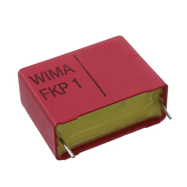
D
WIMA FKP 1
Polypropylene (PP) Capacitors for Very High Pulse Applications with Metal Foil
Electrodes and Metallized Internal Series Connection in PCM 15 mm to 52.5 mm.
Capacitances from 100 pF to 4.7 mF. Rated Voltages from 400 VDC to 6000 VDC.
Special Features
Electrical Data
˜ Extremely high pulse duty
˜ Self-healing
˜ Internal series connection
˜ Very low dissipation factor
˜ Negative capacitance change
versus temperature
˜ AEC-Q200 qualified
for PCM 37.5 mm (for larger box
sizes on request)
˜ According to RoHS 2011/65/EU
Typical Applications
For high pulse and high frequency
applications e.g.
˜ Switch mode power supplies
˜ Converters in drives and power
electronics
˜ Deflection systems in monitors
and TV-sets
˜ Electronic ballasts
Construction
Dielectric:
Polypropylene (PP) film
Capacitor electrodes:
Aluminium foil and double-sided metallized
plastic film
Internal construction:
Plastic film
Metal foil electrode
Electrode carrier
plastic film metallized
on both sides
Metal contact layer
(schoopage)
Terminating wire
06.21
Encapsulation:
Solvent-resistant, flame-retardant plastic
case with epoxy resin seal, UL 94 V-0
Terminations:
Tinned wire.
Marking:
Colour: Red. Marking: Black.
Capacitance range:
100 pF to 4.7 mF (E12-values on request)
Rated voltages:
400 VDC, 630 VDC, 1000 VDC, 1250 VDC,
1600 VDC, 2000 VDC, 4000 VDC,
6000 VDC
Capacitance tolerances:
±20%, ±10%, ±5% (other tolerances are
available subject to special enquiry)
Operating temperature range:
–55+ C to +105+ C
Climatic test category:
55/100/56 in accordance with IEC
Test voltage: 2 sec
Dielectric absorption: 0.05 %
Insulation resistance at +20+ C:
C T 0.1 mF: 1 x 10 5 M¸
C 0.1 mF: 30 000 sec (M¸ x mF)
Measuring voltage: 100 V/1 min.
Voltage derating:
A voltage derating factor of 1.35 % per K
must be applied from +85+ C for DC
voltages and from +75+ C for AC
voltages
Reliability:
Operational life 300 000 hours
Failure rate 1 fit (0.5 x U r and 40+ C)
PCM
4000 VDC
4000 VDC
6000 VDC
37.5
37.5
2 Ur
2 Ur
2 Ur
1.6 U r
1.6 U r
1.2 U r
Dissipation factors at +20+ C: tan d
at f
1 kHz
10 kHz
100 kHz
C 0.1 mF 0.1
mF P C 1.0 mF C 1.0 mF
5 x10 -4
5 x 10⁻⁴
5 x 10⁻⁴
-4
-4
–
6 x10
6 x 10
–
10 x 10-4 –
Maximum pulse rise time:
Capacitance max. pulse rise time V/msec at T A < 40) C
pF/mF
400 VDC 630 VDC 1000 VDC 1250 VDC 1600 VDC 2000 VDC 4000 VDC 6000 VDC
100
... 220
– – – –
56000
56000
– –
330
... 680
– – – –
51000
56000
56000
56000
1000
... 2200 29000 29000 29000 29000 46000 51000 51000 51000
3300
... 6800
9000 14000 27000 29000 29000 29000 29000 29000
0.01
... 0.022
9000 11000 11000 11000 11000 13000 13000 13000
0.033 ... 0.068
9000 11000 11000 11000 11000 11000 13000 13000
0.1 ... 0.22 7000 11000 11000 11000 11000 11000 13000 13000
0.33 ... 0.68 6000 10000 11000 11000 11000 11000 –
–
1.0 ... 2.2 5000 6600 8300 9500 11000
–
–
–
3.3 ... 4.7 2500
– – – – – – –
Mechanical Tests
Pull test on pins:
d T 0.8 l: 10 N in direction of pins
d > 0.8 l: 20 N in direction of pins
according to IEC 60068-2-21
Vibration:
6 hours at 10 ... 2000 Hz and 0.75 mm
displacement amplitude or 10 g in
accordance with IEC 60068-2-6
Low air density:
1kPa = 10 mbar in accordance with
IEC 60068-2-13
Bump test:
4000 bumps at 390 m/sec2
in accordance with IEC 60068-2-29
Packing
Available taped and reeled up to and
including case size 15 x 26 x 31.5 /
PCM 27.5 mm.
Detailed taping information and graphs
at the end of the catalogue.
For further details and graphs please
refer to Technical Information.
79
D
WIMA FKP 1
Continuation
General Data
Capacitance
1000
1500
2200
3300
4700
6800
W
pF 5
„ 5
„ 5
„ 5
„ 5
„ 5
400 VDC/250 VAC*
PCM**
Part number
H
L
11
11
11
11
11
11
18
18
18
18
18
18
15
15
15
15
15
15
W
FKP1G011004B_ _ _ _ _ _ 5
FKP1G011504B_ _ _ _ _ _ 5
FKP1G012204B_ _ _ _ _ _ 5
FKP1G013304B_ _ _ _ _ _ 5
FKP1G014704B_ _ _ _ _ _ 5
FKP1G016804B_ _ _ _ _ _ 6
630 VDC/400 VAC*
PCM**
Part number
H
L
11
11
11
11
11
12.5
18
18
18
18
18
18
15
15
15
15
15
15
FKP1J011004B_ _ _ _ _ _
FKP1J011504B_ _ _ _ _ _
FKP1J012204B_ _ _ _ _ _
FKP1J013304B_ _ _ _ _ _
FKP1J014704B_ _ _ _ _ _
FKP1J016804C_ _ _ _ _ _
0.01 mF 5 11 18 15 FKP1G021004B_ _ _ _ _ _ 7 14 18 15 FKP1J021004D_ _ _ _ _ _
5 14 26.5 22.5 FKP1J021005A_ _ _ _ _ _
0.015 „ 6 12.5 18 15 FKP1G021504C_ _ _ _ _ _ 8 15 18 15 FKP1J021504F_ _ _ _ _ _
6 15 26.5 22.5 FKP1J021505B_ _ _ _ _ _
0.022 „ 7 14 18 15 FKP1G022204D_ _ _ _ _ _ 7 16.5 26.5 22.5 FKP1J022205D_ _ _ _ _ _
5 14 26.5 22.5 FKP1G022205A_ _ _ _ _ _
0.033 „ 8 15 18 15 FKP1G023304F_ _ _ _ _ _
8.5 18.5 26.5 22.5 FKP1J023305F_ _ _ _ _ _
6 15 26.5 22.5 FKP1G023305B_ _ _ _ _ _
0.047 „ 7 16.5 26.5 22.5 FKP1G024705D_ _ _ _ _ _ 10.5 20.5 26.5 22.5 FKP1J024705H_ _ _ _ _ _
9 19 31.5 27.5 FKP1J024706A_ _ _ _ _ _
0.068 „
8.5 18.5 26.5 22.5 FKP1G026805F_ _ _ _ _ _
11 21 31.5 27.5 FKP1J026806B_ _ _ _ _ _
9 19 41.5 37.5 FKP1J026807A_ _ _ _ _ _
0.1 mF 10.5 20.5 26.5 22.5 FKP1G031005H_ _ _ _ _ _
9 19 31.5 27.5 FKP1G031006A_ _ _ _ _ _
0.15 „
11 21 31.5 27.5 FKP1G031506B_ _ _ _ _ _
0.22 „
13 24 31.5 27.5 FKP1G032206D_ _ _ _ _ _
11 22 41.5 37.5 FKP1G032207B_ _ _ _ _ _
0.33 „
13 24 41.5 37.5 FKP1G033307C_ _ _ _ _ _
0.47 „
17 29 41.5 37.5 FKP1G034707E_ _ _ _ _ _
0.68 „
19 32 41.5 37.5 FKP1G036807F_ _ _ _ _ _
13
11
13
15
24
22
24
26
19
20
24
32 41.5 37.5 FKP1J033307F_ _ _ _ _ _
39.5 41.5 37.5 FKP1J034707G_ _ _ _ _ _
45.5 41.5 37.5 FKP1J036807H_ _ _ _ _ _
1.0 mF 20 39.5 41.5 37.5 FKP1G041007G_ _ _ _ _ _
1.5 „
31 46 41.5 37.5 FKP1G041507I_ _ _ _ _ _
2.2 „
35 50 41.5 37.5 FKP1G042207J_ _ _ _ _ _
3.3 „
35 50 57 52.5 FKP1G043309F_ _ _ _ _ _
4.7 „
45 65 57 52.5 FKP1G044709J_ _ _ _ _ _
35
50 41.5 37.5 FKP1J041007J_ _ _ _ _ _
40
55 41.5 37.5 FKP1J041507K_ _ _ _ _ _
35
50 57 52.5 FKP1J041509F_ _ _ _ _ _
45
55 57 52.5 FKP1J042209H_ _ _ _ _ _
31.5
41.5
41.5
41.5
27.5
37.5
37.5
37.5
FKP1J031006D_ _ _ _ _ _
FKP1J031007B_ _ _ _ _ _
FKP1J031507C_ _ _ _ _ _
FKP1J032207D_ _ _ _ _ _
* AC voltages: f T 1000 Hz; 1.4 x Urms + UDC T Ur
** PCM = Printed circuit module = pin spacing
Dims. in mm.
Ionisation inception level in isolated cases may
be lower than admissible rated AC voltage.
Part number completeion:
Version code: 2-pin
4-pin
Tolerance:
20 %
10 %
5 %
Packing:
bulk
Pin length:
6-2
=
=
=
=
=
=
=
00
D4
M
K
J
S
SD
Taped version see page 161.
Rights reserved to amend design data without prior notification.
06.21
Continuation page 81
80
D
WIMA FKP 1
Continuation
General Data
Capacitance
1000
1500
2200
3300
4700
6800
W
pF 5
„ 5
„ 5
„ 5
„ 6
„ 7
1000 VDC/600 VAC*
L
PCM**
H
11
11
11
11
12.5
14
18
18
18
18
18
18
Part number
15
15
15
15
15
15
FKP1O111004B_ _ _ _ _ _
FKP1O111504B_ _ _ _ _ _
FKP1O112204B_ _ _ _ _ _
FKP1O113304B_ _ _ _ _ _
FKP1O114704C_ _ _ _ _ _
FKP1O116804D_ _ _ _ _ _
0.01 mF 8
15
18
15
FKP1O121004F_ _ _ _ _ _
6
15
26.5
22.5
FKP1O121005B_ _ _ _ _ _
0.015 „ 6
15
26.5
22.5
FKP1O121505B_ _ _ _ _ _
0.022 „
8.5 18.5 26.5 22.5
FKP1O122205F_ _ _ _ _ _
0.033 „ 10.5 20.5 26.5 22.5
FKP1O123305H_ _ _ _ _ _
9
19
31.5
27.5
FKP1O123306A_ _ _ _ _ _
0.047 „
11
21
31.5
27.5
FKP1O124706B_ _ _ _ _ _
0.068 „
13
24
31.5
27.5
FKP1O126806D_ _ _ _ _ _
11
22
41.5
37.5
FKP1O126807B_ _ _ _ _ _
0.1
0.15
0.22
0.33
0.47
0.68
mF
„
„
„
„
„
13
15
19
20
31
35
24
26
32
39.5
46
50
41.5
41.5
41.5
41.5
41.5
41.5
37.5
37.5
37.5
37.5
37.5
37.5
FKP1O131007C_ _ _ _ _ _
FKP1O131507D_ _ _ _ _ _
FKP1O132207F_ _ _ _ _ _
FKP1O133307G_ _ _ _ _ _
FKP1O134707I_ _ _ _ _ _
FKP1O136807J_ _ _ _ _ _
1.0 mF
1.5 „
2.2 „
40
35
45
45
55
50
55
65
41.5
57
57
57
37.5
52.5
52.5
52.5
FKP1O141007K_ _ _ _ _ _
FKP1O141009F_ _ _ _ _ _
FKP1O141509H_ _ _ _ _ _
FKP1O142209J_ _ _ _ _ _
* AC voltages: f T 1000 Hz; 1.4 x Urms + UDC T Ur
** PCM = Printed circuit module = pin spacing
Part number completion:
Dims. in mm.
Version code: 2-pin
4-pin
Tolerance:
20 %
10 %
5 %
Packing:
bulk
Pin length:
6-2
Ionisation inception level in isolated cases may
be lower than admissible rated AC voltage.
=
=
=
=
=
=
=
00
D4
M
K
J
S
SD
Taped version see page 161.
2-pin version
4-pin version
P d
W PCM b P d c
PCM
0.8 15 - 27.5
1.0 37.5
pin
pin
c
pin
c
17
19
20
24
31
35
40
35
45
37.5 10
37.5 10
37.5 12.5
37.5 12.5
37.5 20
37.5 20
37.5 20
52.5 20
52.5 20
1.0 0.4
1.0 0.4
1.0 0.4
1.0 0.4
1.0 0.4
1.0 0.4
1.0 0.4
1.2 0.8
1.2 0.8
Rights reserved to amend design data without prior notification
06.21
Continuation page 82
81
D
WIMA FKP 1
Continuation
General Data
Capacitance
100
150
220
330
470
680
W
H
1250 VDC/600 VAC*
L PCM**
Part number
W
H
pF 5 11
„ 5 11
„ 5 11
„ 5 11
„ 5 11
„ 5 11
1600 VDC/650 VAC*
L PCM**
Part number
18
18
18
18
18
18
15
15
15
15
15
15
FKP1T001004B_ _ _ _ _ _
FKP1T001504B_ _ _ _ _ _
FKP1T002204B_ _ _ _ _ _
FKP1T003304B_ _ _ _ _ _
FKP1T004704B_ _ _ _ _ _
FKP1T006804B_ _ _ _ _ _
1000 pF
5 11 18 15 FKP1R011004B_ _ _ _ _ _ 6 12.5 18 15 FKP1T011004C_ _ _ _ _ _
5 14 26.5 22.5 FKP1T011005A_ _ _ _ _ _
1500 „
5 11 18 15 FKP1R011504B_ _ _ _ _ _ 7 14 18 15 FKP1T011504D_ _ _ _ _ _
5 14 26.5 22.5 FKP1T011505A_ _ _ _ _ _
2200 „
5 11 18 15 FKP1R012204B_ _ _ _ _ _ 8 15 18 15 FKP1T012204F_ _ _ _ _ _
5 14 26.5 22.5 FKP1T012205A_ _ _ _ _ _
3300 „
6 12.5 18 15 FKP1R013304C_ _ _ _ _ _ 6 15 26.5 22.5 FKP1T013305B_ _ _ _ _ _
4700 „
7 14 18 15 FKP1R014704D_ _ _ _ _ _ 7 16.5 26.5 22.5 FKP1T014705D_ _ _ _ _ _
6800 „
8 15 18 15 FKP1R016804F_ _ _ _ _ _
8.5 18.5 26.5 22.5 FKP1T016805F_ _ _ _ _ _
5 14 26.5 22.5 FKP1R016805A_ _ _ _ _ _
0.01
0.015
0.022
0.033
0.047
0.068
mF
„
„
„
„
7 16.5 26.5 22.5 FKP1R021005D_ _ _ _ _ _ 10.5 20.5 26.5 22.5 FKP1T021005H_ _ _ _ _ _
8.5 18.5 26.5 22.5 FKP1R021505F_ _ _ _ _ _ 11 21 31.5 27.5 FKP1T021506B_ _ _ _ _ _
10.5 20.5 26.5 22.5 FKP1R022205H_ _ _ _ _ _ 11 21 31.5 27.5 FKP1T022206B_ _ _ _ _ _
11 21 31.5 27.5 FKP1R023306B_ _ _ _ _ _ 13 24 31.5 27.5 FKP1T023306D_ _ _ _ _ _
9 19 41.5 37.5 FKP1R023307A_ _ _ _ _ _ 13 24 41.5 37.5 FKP1T023307C_ _ _ _ _ _
13 24 31.5 27.5 FKP1R024706D_ _ _ _ _ _ 13 24 41.5 37.5 FKP1T024707C_ _ _ _ _ _
11 22 41.5 37.5 FKP1R024707B_ _ _ _ _ _
11 22 41.5 37.5 FKP1R026807B_ _ _ _ _ _ 15 26 41.5 37.5 FKP1T026807D_ _ _ _ _ _
mF
„
„
„
„
„
15
17
19
24
31
40
26
29
32
45.5
46
55
41.5
41.5
41.5
41.5
41.5
41.5
37.5
37.5
37.5
37.5
37.5
37.5
FKP1R031007D_ _ _ _ _ _ 17 29 41.5 37.5
FKP1R031507E_ _ _ _ _ _ 20 39.5 41.5 37.5
FKP1R032207F_ _ _ _ _ _ 24 45.5 41.5 37.5
FKP1R033307H_ _ _ _ _ _ 31 46 41.5 37.5
FKP1R034707I_ _ _ _ _ _ 40 55 41.5 37.5
FKP1R036807K_ _ _ _ _ _ 35 50 57 52.5
FKP1T031007E_ _ _ _ _ _
FKP1T031507G_ _ _ _ _ _
FKP1T032207H_ _ _ _ _ _
FKP1T033307I_ _ _ _ _ _
FKP1T034707K_ _ _ _ _ _
FKP1T036809F_ _ _ _ _ _
1.0 mF
1.5 „
35
45
50
65
57
57
52.5
52.5
FKP1R041009F_ _ _ _ _ _ 45 55 57 52.5
FKP1R041509J_ _ _ _ _ _
FKP1T041009H_ _ _ _ _ _
0.1
0.15
0.22
0.33
0.47
0.68
„
* AC voltages: f T 1000 Hz; 1.4 x Urms + UDC T Ur
** PCM = Printed circuit module = pin spacing
Dims. in mm.
Part number completion:
Ionisation inception level in isolated cases may
be lower than admissible rated AC voltage.
Version code: 2-pin
4-pin
Tolerance:
20 %
10 %
5 %
Packing:
bulk
Pin length:
6-2
=
=
=
=
=
=
=
00
D4
M
K
J
S
SD
Taped version see page 161.
Rights reserved to amend design data without prior notification
06.21
Continuation page 83
82
D
WIMA FKP 1
Continuation
General Data
Capacitance
W
2000 VDC/700 VAC*
L PCM**
Part number
H
W
4000 VDC/700 VAC*
L PCM**
Part number
H
100
150
220
330
470
680
pF
„
„
„
„
„
5 11 18 15
5 11 18 15
5 11 18 15
6 12.5 18 15
6 12.5 18 15
6 12.5 18 15
1000
1500
2200
3300
4700
6800
pF
7 14 18 15 FKP1U011004D_ _ _ _ _ _
5 14 26.5 22.5 FKP1X011005A_ _ _ _ _ _
5 14 26.5 22.5 FKP1U011005A_ _ _ _ _ _
6 15 26.5 22.5 FKP1U011505B_ _ _ _ _ _ 7 16.5 26.5 22.5 FKP1X011505D_ _ _ _ _ _
7 16.5 26.5 22.5 FKP1U012205D_ _ _ _ _ _
8.5 18.5 26.5 22.5 FKP1X012205F_ _ _ _ _ _
7 16.5 26.5 22.5 FKP1U013305D_ _ _ _ _ _ 10.5 20.5 26.5 22.5 FKP1X013305H_ _ _ _ _ _
8.5 18.5 26.5 22.5 FKP1U014705F_ _ _ _ _ _ 11 21 31.5 27.5 FKP1X014706B_ _ _ _ _ _
10.5 20.5 26.5 22.5 FKP1U016805H_ _ _ _ _ _ 13 24 31.5 27.5 FKP1X016806D_ _ _ _ _ _
„
„
„
„
„
FKP1U001004B_ _ _ _ _ _
FKP1U001504B_ _ _ _ _ _
FKP1U002204B_ _ _ _ _ _
FKP1U003304C_ _ _ _ _ _
FKP1U004704C_ _ _ _ _ _
5 14 26.5 22.5 FKP1X004705A_ _ _ _ _ _
FKP1U006804C_ _ _ _ _ _ 5 14 26.5 22.5 FKP1X006805A_ _ _ _ _ _
0.01
0.015
0.022
0.033
0.047
0.068
mF
„
„
„
„
„
11 21 31.5 27.5 FKP1U021006B_ _ _ _ _ _ 15 26 31.5 27.5 FKP1X021006F_ _ _ _ _ _
13 24 31.5 27.5 FKP1U021506D_ _ _ _ _ _ 13 24 41.5 37.5 FKP1X021507C_ _ _ _ _ _
15 26 31.5 27.5 FKP1U022206F_ _ _ _ _ _ 17 29 41.5 37.5 FKP1X022207E_ _ _ _ _ _
13 24 41.5 37.5 FKP1U022207C_ _ _ _ _ _
13 24 41.5 37.5 FKP1U023307C_ _ _ _ _ _ 20 39.5 41.5 37.5 FKP1X023307G_ _ _ _ _ _
17 29 41.5 37.5 FKP1U024707E_ _ _ _ _ _ 24 45.5 41.5 37.5 FKP1X024707H_ _ _ _ _ _
19 32 41.5 37.5 FKP1U026807F_ _ _ _ _ _ 31 46 41.5 37.5 FKP1X026807I_ _ _ _ _ _
0.1
0.15
0.22
0.33
0.47
0.68
mF
„
„
„
„
„
20 39.5 41.5 37.5
24 45.5 41.5 37.5
35 50 41.5 37.5
40 55 41.5 37.5
45 55 57 52.5
45 65 57 52.5
FKP1U031007G_ _ _ _ _ _ 35 50 41.5 37.5 FKP1X031007J_ _ _ _ _ _
FKP1U031507H_ _ _ _ _ _ 40 55 41.5 37.5 FKP1X031507K_ _ _ _ _ _
FKP1U032207J_ _ _ _ _ _ 45 55 57 52.5 FKP1X032209H_ _ _ _ _ _
FKP1U033307K_ _ _ _ _ _
FKP1U034709H_ _ _ _ _ _
FKP1U036809J_ _ _ _ _ _
* AC voltages: f T 1000 Hz; 1.4 x Urms + UDC T Ur
** PCM = Printed circuit module = pin spacing
Part number completion:
Dims. in mm.
Version code: 2-pin
4-pin
Tolerance:
20 %
10 %
5 %
Packing:
bulk
Pin length:
6-2
Ionisation inception level in isolated cases may
be lower than admissible rated AC voltage.
=
=
=
=
=
=
=
00
D4
M
K
J
S
SD
Taped version see page 161.
2-pin version
4-pin version
P d
W PCM b P d c
PCM
0.8 15 - 27.5
1.0 37.5
pin
pin
c
pin
c
17
19
20
24
31
35
40
35
45
37.5 10
37.5 10
37.5 12.5
37.5 12.5
37.5 20
37.5 20
37.5 20
52.5 20
52.5 20
1.0 0.4
1.0 0.4
1.0 0.4
1.0 0.4
1.0 0.4
1.0 0.4
1.0 0.4
1.2 0.8
1.2 0.8
Rights reserved to amend design data without prior notificationn.
06.21
Continuation page 84
83
D
WIMA FKP 1
Continuation
General Data
Capacitance
W
6000 VDC/700 VAC*
L PCM**
Part number
H
Dims. in mm.
470 pF 5 14 26.5 22.5 FKP1Y004705A_ _ _ _ _ _
680 „ 5 14 26.5 22.5 FKP1Y006805A_ _ _ _ _ _
1000
1500
2200
3300
4700
6800
pF
5 14 26.5 22.5 FKP1Y011005A_ _ _ _ _ _
„ 7 16.5 26.5 22.5 FKP1Y011505D_ _ _ _ _ _
„
10.5 20.5 26.5 22.5 FKP1Y012205H_ _ _ _ _ _
„ 10.5 20.5 26.5 22.5 FKP1Y013305H_ _ _ _ _ _
„
11 21 31.5 27.5 FKP1Y014706B_ _ _ _ _ _
„
13 24 31.5 27.5 FKP1Y016806D_ _ _ _ _ _
0.01
0.015
0.022
0.033
0.047
0.068
mF 15 26 31.5 27.5 FKP1Y021006F_ _ _ _ _ _
„
13 24 41.5 37.5 FKP1Y021507C_ _ _ _ _ _
„
17 29 41.5 37.5 FKP1Y022207E_ _ _ _ _ _
„
20 39.5 41.5 37.5 FKP1Y023307G_ _ _ _ _ _
„
24 45.5 41.5 37.5 FKP1Y024707H_ _ _ _ _ _
„
31 46 41.5 37.5 FKP1Y026807I_ _ _ _ _ _
0.1 mF
0.15 „
0.22 „
Ionisation inception level in isolated cases may
be lower than admissible rated AC voltage.
Part number completion:
Version code: 2-pin
4-pin
Tolerance:
20 %
10 %
5 %
Packing:
bulk
Pin length:
6-2
35 50 41.5 37.5 FKP1Y031007J_ _ _ _ _ _
40 55 41.5 37.5 FKP1Y031507K_ _ _ _ _ _
45 55 57 52.5 FKP1Y032209H_ _ _ _ _ _
=
=
=
=
=
=
=
00
D4
M
K
J
S
SD
Taped version see page 161.
* AC voltages: f T 1000 Hz; 1.4 x Urms + UDC T Ur
** PCM = Printed circuit module = pin spacing
Rights reserved to amend design data without prior notificationn.
10
Impedance change with frequency
(general guide).
1
PCM 22.5
Z
Z
7
5
--
--
22
0.
47
0.
--
µF
0
1.
107
108
0.001
106
3
5
7
107
f/Hz
PCM 15
0
pF
--
7
5
--
3
00
7
5
pF
3
µF
0.1
7
5
3
0.01
7
5
µF
03
0.01
00
5
3
pF
68
01
0.
pF
7
5
22
--
3
-0.
0.1
47
0.
--
7
5
Z
--
0.1
-0
15
Z
pF
00
F
47
µ
-01
0.
µF
-2 F
02 µ
0. 33 µF
-- 0.0 47 µF
-- 0.0.068
-- - 0
-
1
1
PCM 52.5
10
Z
108
f/Hz
1
10
PCM 37.5
µF
7
--
3
µF
5
--
pF
7
5
µF
3
--
00
22
0.01
2
7
04
0.
106
3
02
0.
--
3
pF
00
F
47 1 µ
0
0.
--
7
5
0.01
10
----
0.1
pF F
0
p
68 00
--
3
µF
2
02 3 µF
0.
F
03 8 µ
-0.
06
0.
µF
1
µF
0.
0.1
7
5
--
1
4.7 µF
3
PCM 27.5
3
0.01
106
3
5
7
µF
107
108
0.001
106
3
5
7
107
108
f/Hz
0.001
105
3
5
7
106
107
f/Hz
06.21
f/Hz
84
Continuation page 85
D
WIMA FKP 1
Continuation
Permissible AC voltage in relation to frequency till
15) C internal temperature rise (general guide).
The information behind the cross bar denote the PCM
of the measured value.
103
103
Urms
V
650
Urms
V
250
2
1.0
µF
/3
7.5
102
5
400 VDC
103
2
5
2
0.0
33
µF
/15
0.2
2µ
F/2
4.
7.5
7µ
F/
52
.5
2
101
0.0
47
µF
/22
.5
104
2
5
105
2
5 f 106
Hz
630 VDC
2
2
5
104
2
5
105
2
5 f 106
Hz
103
150
0p
F/1
5
0.0
22
µ
F/2
0.0
7.5
4
0.0 7 µF
/27
68
.5
µF
/3
7.5
2
102
2
5
104
2
5
105
1000 VDC
2
5 f 106
Hz
470 pF/15
15
00
pF
/22
0.0
.5
1µ
F/
0.0
27
68
.
5
µF
/3
7.5
102
5
2000 VDC
2
101
103
2
5
104
2
Urms
V
5
0.
1µ
F/
37
.5
2
102
5
2
4000 VDC
105
2
5 f 106
Hz
15
00 68
pF/ 0 p
22 F/2
.5 2.5
0.0
1µ
F/
27
0.
04
.5
7µ
F/
37
.5
2
103
2
5
104
2
5
105
2
5 f 106
Hz
68
00
pF
/15
0.0
33
µF
/27
.5 0.01
5µ
0.1
F/2
5µ
2.5
F/3
7.5
2
102
5
101
103
2
5
104
2
5
103
700
103
600
Urms
V
1250 VDC
2
2
5 f 106
Hz
10
00
pF/
22
47 .5
00
pF
/2
7.5
0.
04
7
0.
µF
15
/3
7.
µF
5
/3
7.
5
Urms
V
2
102
5
105
6000 VDC
2
103
2
5
104
2
5
105
2
5 f 106
Hz
101
103
2
5
104
2
5
105
2
5 f 106
Hz
06.21
101
103
103
700
600
Urms
V
101
101
2
0.0
1µ
F/2
2.5
0.0
68
µF
/2
0.
7.5
47
µF
/3
7.
5
102
5
1600 VDC
Urms
V
0.0
15
0.2
µF
2µ
/1
5
F/
37
.5
103
5
103
700
2
101
102
47
00
pF/
22
.5
0.0
22
µF/
27
.5
2
103
Urms
V
400
5
100 pF/15
0.0
47
0.
µF
33
/3
7.5
µF
/3
7.
5
Continuation page 86
85
D
WIMA FKP 1
Continuation
Permissible AC current in relation to frequency till
15) C internal temperature rise (general guide).
The information behind the cross bar denote the PCM
of the measured value.
102
Irms
A
102
Irms
A
4.7 µF/52.5
10
10
0.33 µF/37.5
0,047 µF/37.5
0.022 µF/27.5
4700 pF/22.5
1.0 µF/37.5
0.047 µF/22.5
1
10-1
10-2
0.22 µF/27.5
0.033 µF/15
10-1
400 VDC
103
2
5
104
2
5
105
2
5 f 106
Hz
10
0.47 µF/37.5
0.22 µF/37.5
0.015 µF/15
1
10-1
103
2
5
104
0.01 µF/22.5
5
105
103
2
5
104
2
5
105
10
2
5
f 106
Hz
0.068 µF/37.5
2
0.01 µF/27.5
1500 pF/22.5
1
10-1
630 VDC
5
f 106
Hz
10-2
15
pF/
470
103
2
5
104
2
102
Irms
A
10
10
0.068 µF/37.5
0.022 µF/22.5
1
5
2000 VDC
105
0.1 µF/37.5
2
5 f 106
Hz
0.047 µF/37.5
0,01 µF/27.5
0.047 µF/27.5
1
1500 pF/15
1500 pF/22.5
680 pF/22.5
10-1
10-1
1000 VDC
4000 VDC
10-2
103
2
5
104
2
5
105
2
5 f 106
Hz
103
2
5
104
2
5
105
2
5 f 106
Hz
102
Irms
A
102
Irms
A
10
0.15 µF/37.5
0.033 µF/27,5
0.015 µF/22.5
6800 pF/15
1
0.15 µF/37.5
10
0.047 µF/37.5
4700 pF/27.5
1
2.5
F/2
0p
100
10-1
10-1
1250 VDC
102
2
5
103
2
5
104
2
5 f 105
Hz
10-2
103
2
5
104
2
5
6000 VDC
105
2
5
f 106
Hz
06.21
10-2
2
0.068 µF/27.5
102
Irms
A
10-2
10-2
1600 VDC
15
pF/
100
102
Irms
A
102
Irms
A
10-2
1
86
D
Recommendation for Processing
and Application of
Through-Hole Capacitors
Soldering Process
Internal temperature of the capacitor must
be kept as follows:
Polyester:
preheating: T max. T 125° C
soldering: T max. T 135° C
Polypropylene: preheating: Tmax. T 100° C
soldering: T max. T 110° C
Single wave soldering
Soldering bath temperature: T P 260 ° C
Dwell time:
t P 5 sec
Double wave soldering
Soldering bath temperature: T P 260 ° C
Dwell time:
St P 5 sec
Due to different soldering processes and
heat requirements the graphs are to be
regarded as a recommendation only.
WIMA Quality and Environmental Philosophy
ISO 9001:2015 Certification
ISO 9001:2015 is an international basic
standard of quality assurance systems
for all branches of industry. The approval
according to ISO 9001:2015 of our factories by the infaz (Institut für Auditierung und
Zertifizierung) certifies that organisation,
equipment and monitoring of quality assurance in our factories correspond to internationally recognized standards.
WIMA WPCS
The WIMA Process Control System (WPCS)
is a quality surveillance and optimization
system developed by WIMA. WPCS is a
major part of the quality-oriented WIMA
production. Points of application during
production process:
All WIMA capacitors, irrespective of
whether through-hole devices or SMD,
are made of environmentally friendly
materials. Neither during manufacture
nor in the product itself any toxic substances are used, e.g.
–
–
–
–
–
Lead
PCB
CFC
Hydrocarbon chloride
Chromium 6+
–
–
–
–
–
PBB/PBDE
Arsenic
Cadmium
Mercury
etc.
We merely use pure, recyclable materials
for packing our components, such as:
” carton
” cardboard
” adhesive tape made of paper
” polystyrene
We almost completely refrain from using
packing materials such as:
” adhesive tapes made of plastic
” metal clips
RoHS Compliance
According to the RoHS Directive 2011/65/EU
as amended from time to time certain hazardous substances like e.g. lead, cadmium,
mercury must not be used any longer in
electronic equipment as of July 1st, 2006. For
the sake of the environment WIMA has refraind from using such substances since years
already.
WIMA Kondensatoren sind bleifrei
konform RoHS 2011/65/EU
WIMA capacitors are lead free
in accordance with RoHS 2011/65/EU
Tape for lead-free WIMA capacitors
DIN EN ISO 14001:2004
WIMA’s environmental management has
been established in accordance with the
guidelines of DIN EN ISO 14001:2004 to
optimize the production processes with
regard to energy and resources.
06.21
” incoming material inspection
” metallization
” film inspection
” schoopage
” pre-healing
” pin attachment
” cast resin preparation/
encapsulation
” 100% final inspection
” Testing as per customer requirements
WIMA Environmental Policy
15
D
Typical Dimensions for
Taping Configuration
Vh
P
P2
Diagram 1:
PCM 2.5/5/7.5mm
W
W1
W0
H
H1
W2
P1
D0
d
P
t
F
P0
H1
P
P1
H
P1
d
d
F
P0
P2
Diagram 2: PCM 10/15 mm
Diagram 3: PCM 22.5 and 27.5*mm
*PCM 27.5 taping possible with two feed holes between components
Designation
Carrier tape width
Dimensions for Radial Taping
Symbol PCM 2.5 taping
W
P0
P2
F
PCM 5 taping
PCM 7.5 taping
PCM 10 taping*
PCM 15 taping*
PCM 22.5 taping
PCM 27.5 taping
18.0 p0.5 18.0 p0.5 18.0 p0.5 18.0 p0.5 18.0 p0.5 18.0 p0.5 18.0 p0.5
for hot-sealing
for hot-sealing
for hot-sealing
for hot-sealing
for hot-sealing
for hot-sealing
for hot-sealing
Hold-down tape width
W0 6.0
6.0
12.0
12.0
12.0
12.0
12.0
adhesive
tape adhesive tape adhesive tape adhesive tape adhesive tape adhesive tape adhesive tape
Hole position
W1 9.0 p0.5 9.0 p0.5 9.0 p0.5 9.0 p0.5 9.0 p0.5 9.0 p0.5 9.0 p0.5
Hold-down tape position
W 2
Feed hole diameter
D0 4.0 p0.2 4.0 p0.2 4.0 p0.2 4.0 p0.2 4.0 p0.2 4.0 p0.2 4.0 p0.2
P
12.7 p1.0 12.7 p1.0 12.7 p1.0 25.4 p1.0 25.4 p1.0 38.1 p1.5 3*8.1 p1.5 or 50.8 p1.5
0.5 to 3.0 max.
Pitch of component
Feed hole pitch
P0 12.7 p0.3
cumulative pitch
error max.
1.0 mm/20 pitch
0.5 to 3.0 max.
12.7 p0.3
cumulative pitch
error max.
1.0 mm/20 pitch
0.5 to 3.0 max.
12.7 p0.3
cumulative pitch
error max.
1.0 mm/20 pitch
0.5 to 3.0 max.
12.7 p0.3
0.5 to 3.0 max.
cumulative pitch
error max.
1.0 mm/20 pitch
12.7 p0.3
cumulative pitch
error max.
1.0 mm/20 pitch
0.5 to 3.0 max.
12.7 p0.3
cumulative pitch
error max.
1.0 mm/20 pitch
0.5 to 3.0 max.
12.7 p0.3
Feed hole centre
to pin
P1 5.1 p0.5 3.85 p0.7 2.6 p0.7 7.7 p0.7 5.2 p0.7 7.8 p0.7 5.3 p0.7
Hole centre to
component centre
P2 6.35 p1.3 6.35 p1.3 6.35 p1.3 12.7 p1.3 12.7 p1.3 19.05 p1.3 19.05 p1.3
Feed hole centre to bottom
H
edge of the component
cumulative pitch
error max.
1.0 mm/20 pitch
16.5 p0.3 16.5 p0.3 16.5 p0.5 16.5 p0.5 16.5 p0.5 16.5 p0.5 16.5 p0.5
18.5 p0.5 18.5 p0.5 18.5 p0.5 18.5 p0.5 18.5 p0.5 18.5 p0.5 18.5 p0.5
Feed hole centre to top
H+Hcomponent < H1 H+Hcomponent < H1 H+Hcomponent < H1 H+Hcomponent < H1 H+Hcomponent < H1 H+Hcomponent < H1 H+Hcomponent < H1
H
edge of the component 1
32.25 max.
32.25 max.
24.5 to 31.5
25.0 to 31.5
26.0 to 37.0
30.0 to 43.0
35.0 to 45.0
Pin spacing at
+0.8
F 2.5 p0.5 5.0 7.5 p0.8 10.0 p0.8 15 p0.8 22.5 p0.8 27.5 p0.8
upper edge of carrier tape –0.2
Pin diameter
d
0.4 p0.05 0.5 p0.05
Component alignment
Dh
p 2.0 max.
Total tape thickness
t
p 2.0 max.
+0.06 +0,06
+0,08 +0,08 +0.08
„
0.5 p0.05 or 0.6 –0.05 „ 0.5 p0.05 or 0.6 –0.05 0.8 –0.05 0.8 –0.05 0.8 –0.05
p 3.0 max.
p 3.0 max.
p 3.0 max.
p 3.0 max.
p 3.0 max.
0.6 p0.2 0.6 p0.2 0.6 p0.2 0.6 p0.2 0.6 p0.2 0.6 p0.2 0.6 p0.2
ROLL/AMMO
Package
(see also page 162)
52 p2 depending on
P 360 max.
B p2 comp. dimensions
REEL P 30 p1 58
Unit
AMMO
52 p2 54 p2
500 max.
B 60 p2
REEL P 360 max. B 58 p2 or REEL PP 25
p1
P 30 p1 66 p2
68 p2
depending
on PCM and
component dimensions
see details page 163.
Dims in mm.
06.21
„ Diameter of pins see General Data.
Please clarify customer-specific deviations with the manufacturer.
* PCM 10 and PCM 15 can be crimped to PCM 7.5.
Position of components according to PCM 7.5 (sketch 1). P 0 = 12.7 or 15.0 is possible
161
D
Types of Tape Packaging of
Capacitors for Automatic
Radial Insertion
˜ REEL Packaging
340 max.
30±1
25±1
360 max.
500 max.
˜ AMMO Packaging
340 max.
370 max.
˜ ROLL Packaging
34
0m
ax.
50 max.
50 max.
70 max.
.
ax
0 m ax.
34 0 m
49
B
BAR CODE (Labelling)
Labelling of package units in
plain text and with
alphanumerical Bar Code
BARCODE PDF417
BARCODE 2D Datamatrix
„ WIMA supplier number
„ Date code
„ Customer‘s P/O number
„ P/O line
„ Customer‘s part number
„ WIMA part number
„ Quantity
„ WIMA confirmation number
„ Country of origin
„ Customer name
„ Handling unit number
„ Week of delivery.
In addition part description of
article
capacitance value
rated voltage
dimensions
technical note
capacitance tolerance
packing
connecting information
06.21
–
–
–
–
–
–
–
–
162
D
Packing Quantities for Capacitors with
Radial Pins in PCM 2.5 mm to 22.5 mm
Size
PCM
2.5 mm
5 mm
7.5 mm
10 mm
15 mm
22.5 mm
W
2.5
3
3.8
4.6
5.5
2.5
3
3.5
4.5
4.5
5
5.5
5.5
6.5
7.2
7.2
8.5
8.5
11
2.5
3
4
4.5
5
5.7
7.2
3
4
4
4
5
5
6
6
8
5
5
6
6
7
7
8
8
9
9
10
11
5
6
7
8
8.5
10
10.5
10.5
11
12
H
7
7.5
8.5
9
10
6.5
7.5
8.5
6
9.5
10
7
11.5
8
8.5
13
10
14
16
7
8.5
9
9.5
10.5
12.5
12.5
9
8.5
9
9.5
10
11
12
12.5
12
11
13
12.5
14
14
15
15
17
14
16
18
14
14
15
16.5
20
18.5
22
19
20.5
21
24
bulk
L
4.6
4.6
4.6
4.6
4.6
7.2
7.2
7.2
7.2
7.2
7.2
7.2
7.2
7.2
7.2
7.2
7.2
7.2
7.2
10
10
10
10.3
10.3
10.3
10.3
13
13.5
13
13
13.5
13
13
13
13
18
19
18
19
18
19
18
19
18
18
19
18
26.5
26.5
26.5
28
26.5
28
26.5
26.5
26.5
28
Codes
0B
0C
0D
0E
0F
1A
1B
1C
1D
1E
1F
1G
1H
1I
1J
1K
1L
1M
1N
2A
2B
2C
2D
2E
2F
2G
3A
FA
3C
3D
FB
3F
3G
3H
3I
4B
FC
4C
FD
4D
FE
4F
FF
4H
4J
FG
4M
5A
5B
5D
FH
5F
FI
5G
5H
5I
FJ
S
5000
5000
5000
5000
5000
5000
5000
5000
6000
4000
3500
4000
2500
2500
2500
2000
2000
1500
1000
5000
5000
4000
3500
3000
2000
1500
3000
3000
3000
3000
2000
3000
2400
2400
2000
2400
1000
2000
1000
1600
1000
1200
500
1200
900
500
1000
1200
1000
760
500
500
570*
594*
594*
561*
480*
Moulded versions.
Rights reserved to amend design data without prior notification.
06.21
* TPS (Tray-Packing-System). Plate versions may have different packing units.
Samples and pre-production needs on request.
pcs. per packing unit
REEL
AMMO
P 360
P 500
340 x 340
490 x 370
H16.5 H18.5 H16.5 H18.5 H16.5 H18.5 H16.5 H18.5 H16.5 H18.5
N
O
F
I
H
J
A
C
B
D
2200
2500
–
2800
–
2000
2300
–
2300
–
1500
1800
–
1800
–
1200
1500
–
1500
–
900
1200
–
1200
–
2200
2500
–
2800
–
2000
2300
–
2300
–
1600
2000
–
2000
–
1300
1500
–
1500
–
1300
1500
–
1500
–
1100
1400
–
1400
–
1000
1200
–
1200
–
1000
1200
–
1200
–
800
1000
–
1000
–
1000
–
1000
–
700
700
950
–
1000
–
600
800
800
–
–
600
800
800
–
–
500
600
640
–
–
–
2500
4400
2500
–
–
2200
4300
2300
4150
–
1700
3200
1700
3000
–
1500
2900
1400
2700
–
1300
2500
1300
–
–
1000
2200
1100
–
900
–
1800
1000
–
–
1100
2200
–
1900
900
–
1600
–
1450
–
900
1600
–
1450
900
–
1600
–
1400
–
700
1300
–
1200
700
–
1300
–
1100
–
550
1100
–
1000
–
1100
–
1000
550
–
–
400
800
740
1200
–
1150
–
600
–
600
1200
–
1200
–
1000
–
1000
500
–
500
1000
–
1000
–
–
450
900
850
–
450
900
–
850
–
–
400
800
740
–
400
800
–
740
–
–
350
700
650
–
350
700
–
650
–
–
300
650
590
300
600
540
–
–
–
–
800
–
770
700
640
–
–
–
–
–
600
–
550
–
–
–
500
480
–
–
480
–
450
–
–
–
420
380
–
–
400
–
360
400
360
–
–
–
–
–
380
–
350
350
310
–
–
–
ROLL
163
D
Packing Quantities for Capacitors with
Radial Pins in PCM 27.5 mm to 52.5 mm
Size
PCM
pcs. per packing unit
REEL
AMMO
P 360
P 500
340 x 340
490 x 370
H16.5 H18.5 H16.5 H18.5 H16.5 H18.5 H16.5 H18.5 H16.5 H18.5
N
O
F
I
H
J
A
C
B
D
–
–
460/340*
–
–
–
–
380/280*
–
–
–
–
300
–
–
–
–
–
–
–
270
–
–
–
–
–
–
–
–
–
–
–
–
–
–
–
–
–
–
–
–
–
–
–
–
–
–
–
–
–
ROLL
bulk
W
9
11
13
13
15
15
17
17
20
20
H
19
21
24
25
26
26
29
34.5
32
39.5
L
31.5
31.5
31.5
33
31.5
33
31.5
31.5
33
31.5
Codes
6A
6B
6D
FK
6F
FL
6G
6I
FM
6J
S
567*
459*
378*
405*
324*
324*
198*
198*
162*
162*
37.5 mm
9
11
13
15
17
19
20
24
28
31
35
40
19
22
24
26
29
32
39.5
45.5
38
46
50
55
41.5
41.5
41.5
41.5
41.5
41.5
41.5
41.5
41.5
41.5
41.5
41.5
7A
7B
7C
7D
7E
7F
7G
7H
7L
7I
7J
7K
441*
357*
294*
252*
154*
140*
126*
112*
84*
84*
35*
28*
–
–
–
–
–
–
–
–
–
–
–
–
–
–
–
–
–
–
–
–
–
–
–
–
–
–
–
–
–
–
–
–
–
–
–
–
–
–
–
–
–
–
–
–
–
–
–
–
–
–
–
–
–
–
–
–
–
–
–
–
48.5 mm
19
23
27
33
37
31
34
37.5
48
54
56
56
56
56
56
8D
8E
8H
8J
8L
120*
80*
84*
25*
25*
–
–
–
–
–
–
–
–
–
–
–
–
–
–
–
–
–
–
–
–
–
–
–
–
–
52.5 mm
25
30
35
45
45
45
45
50
55
65
57
57
57
57
57
9D
9E
9F
9H
9J
70*
60*
25*
20*
20*
–
–
–
–
–
–
–
–
–
–
–
–
–
–
–
–
–
–
–
–
–
–
–
–
–
27.5 mm
* for 2-inch transport pitches.
* TPS (Tray-Packing-System). Plate versions may have different packing units.
Samples and pre-production needs on request.
Moulded versions.
Rights reserved to amend design data without prior notification.
06.21
Updated data on www.wima.com
164
D
WIMA Part Number System
A WIMA part number consists of 18 digits and is composed as follows:
Field 1 - 4: Type description
Field 5 - 6: Rated voltage
Field 7 - 10: Capacitance
Field 11 - 12: Size and PCM
Field 13 - 14: Version code (e.g. Snubber versions)
Field 15:
Capacitance tolerance
Field 16:
Packing
Field 17 - 18: Pin length (untaped)
1
2
3
4
5
6
7
8
9
10
11
12
13
14
15
16
17
18
M
K
S
2
C
0
2
1
0
0
1
A
0
0
M
S
S
D
20 %
bulk
MKS 2
06.21
Type description:
SMD-PET
= SMDT
SMD-PEN
= SMDN
SMD-PPS
= SMDI
FKP 02
= FKP0
MKS 02
= MKS0
FKS 2
= FKS2
FKP 2
= FKP2
FKS 3
= FKS3
FKP 3
= FKP 3
MKS 2
= MKS2
MKP 2
= MKP2
MKS 4
= MKS4
MKP 4
= MKP4
MKP 10
= MKP1
FKP 4
= FKP4
FKP 1
= FKP1
MKP-X2
= MKX2
MKP-X1 R
= MKX1
MKP-Y2
= MKY2
MP 3-X2
= MPX2
MP 3-X1
= MPX1
MP 3-Y2
= MPY2
MP 3R-Y2
= MPRY
MKP 4F
= MKPF
Snubber MKP = SNMP
Snubber FKP
= SNFP
GTO MKP
= GTOM
DC-LINK MKP 4 = DCP4
DC-LINK MKP 6 = DCP6
DC-LINK HC
= DCHC
63 VDC
Rated voltage:
50 VDC = B0
63 VDC = C0
100 VDC = D0
250 VDC = F0
400 VDC = G0
450 VDC = H0
520 VDC = H2
600 VDC = I0
630 VDC = J0
700 VDC = K0
800 VDC = L0
850 VDC = M0
900 VDC = N0
1000 VDC = O1
1100 VDC = P0
1200 VDC = Q0
1250 VDC = R0
1500 VDC = S0
1600 VDC = T0
1700 VDC = TA
2000 VDC = U0
2500 VDC = V0
3000 VDC = W0
4000 VDC = X0
6000 VDC = Y0
250 VAC = 0W
275 VAC = 1W
300 VAC = 2W
305 VAC = AW
350 VAC = BW
440 VAC = 4W
500 VAC = 5W
...
0.01 mF
Capacitance:
22 pF
= 0022
47 pF
= 0047
100 pF = 0100
150 pF = 0150
220 pF = 0220
330 pF = 0330
470 pF = 0470
680 pF = 0680
1000 pF = 1100
1500 pF = 1150
2200 pF = 1220
3300 pF = 1330
4700 pF = 1470
6800 pF = 1680
0.01 mF = 2100
0.022 mF = 2220
0.047 mF = 2470
0.1 mF = 3100
0.22 mF = 3220
0.47 mF = 3470
= 4100
1 mF
2.2 mF = 4220
4.7 mF = 4470
= 5100
10 mF
= 5220
22 mF
= 5470
47 mF
100 mF = 6100
220 mF = 6220
1000 mF = 7100
1500 mF = 7150
...
2.5 x 6.5 x 7.2
-
Size:
4.8 x 3.3 x 3 Size 1812 = KA
4.8 x 3.3 x 4 Size 1812 = KB
5.7 x 5.1 x 3.5 Size 2220 = QA
5.7 x 5.1 x 4.5 Size 2220 = QB
7.2 x 6.1 x 3 Size 2824 = TA
7.2 x 6.1 x 5 Size 2824 = TB
10.2 x 7.6 x 5 Size 4030 = VA
12.7 x 10.2 x 6 Size 5040 = XA
15.3 x 13.7 x 7 Size 6054 = YA
2.5 x 7 x 4.6 PCM 2.5 = 0B
3 x 7.5 x 4.6 PCM 2.5 = 0C
2.5 x 6.5 x 7.2 PCM 5 = 1A
3 x 7.5 x 7.2 PCM 5
= 1B
2.5 x 7 x 10 PCM 7.5
= 2A
3 x 8.5 x 10 PCM 7.5
= 2B
3 x 9 x 13 PCM 10
= 3A
4 x 9 x 13 PCM 10
= 3C
5 x 11 x 18 PCM 15
= 4B
6 x 12.5 x 18 PCM 15 = 4C
5 x 14 x 26.5 PCM 22.5 = 5A
6 x 15 x 26.5 PCM 22.5 = 5B
9 x 19 x 31.5 PCM 27.5 = 6A
11 x21 x 31.5 PCM 27.5 = 6B
9 x 19 x 41.5 PCM 37.5 = 7A
11 x 22 x 41.5 PCM 37.5 = 7B
19 x 31 x 56 PCM 48.5 = 8D
25 x 45 x 57 PCM 52.5 = 9D
...
Version code:
Standard
=
Version A1
=
Version A1.1.1 =
Version A2
=
...
00
1A
1B
2A
Tolerance:
±20 % =
±10 % =
±5 %
=
±2.5 % =
±1 %
=
...
6 -2
M
K
J
H
E
Packing:
AMMO H16.5 340 x 340
AMMO H16.5 490 x 370
AMMO H18.5 340 x 340
AMMO H18.5 490 x 370
REEL H16.5 360
REEL H16.5 500
REEL H18.5 360
REEL H18.5 500
ROLL H16.5
ROLL H18.5
BLISTER W12 180
BLISTER W12 330
BLISTER W16 330
BLISTER W24 330
Bulk/TPS Standard
...
=A
=B
=C
=D
=F
=H
=I
=J
=N
=O
=P
=Q
=R
=T
=S
Pin length (untaped)
3.5 ±0.5 = C9
6 -2
= SD
16 ±1
= P1
...
Pin length (taped)
none
= 00
The data on this page is not complete and serves only to explain the part number system. Part number information is listed on the
pages of the respective WIMA range.
159
很抱歉,暂时无法提供与“FKP1Y021006F00KSC9”相匹配的价格&库存,您可以联系我们找货
免费人工找货