AC-DC Power Supplies Bus Converter . Power Module Type
Medical
electric
equipment
Power
Factor
Correction
World wide Low Profile Safety
Approvals
Inrush
current
limiting
Isolated
OCP
OVP
Remote
ON/OFF
Parallel
Operation
TUNS-series
Feature
CE marking
AC-DC Power Module Type Converter
Harmonic attenuator (Complies with IEC61000-3-2 class A)
Thin and small size
Built-in overcurrent, overvoltage and thermal protection circuits
Mounting hole (M3 tapped)
Universal input 85 - 264VAC
Peak current (TUNS500F)
Wide input 85 - 305VAC
For medical electric equipment
Constant current regulation
Output voltage can be varied to near 0V
Parallel operation possible
Low voltage directive
RoHS Directive
Safety Approval
UL60950-1, C-UL, EN62368-1
(TUNS50F/100F/300F/500F/700F)
UL62368-1, C-UL, EN62368-1 (TUNS1200F)
ANSI/AAMI ES60601-1, EN60601-1 3rd (TUNS1200F)
5-year warranty
Optional parts
Heat sink
July 13, 2022
TUNS-1
�AC-DC Power Supplies Bus Converter . Power Module Type
TUNS50F
Ordering information
TUN
1
S
2
50
3
F
*�Providing heat sink
as option
R
05
4
5
-O
6
1 Series name
2 Single output
3 Output wattage
4 Universal Input
5 Output voltage
6 Optional
T : with Mounting hole
(f3.4 thru)
*Avoid short circuit between +BC and -BC. It may cause the failure of inside components.
*Keep TRM open, if output voltage adjustment is not necessary.
MODEL
MAX OUTPUT WATTAGE[W]
DC OUTPUT
TUNS50F05
50.0
5V 10A
TUNS50F12
50.4
12V 4.2A
TUNS50F24
50.4
24V 2.1A
SPECIFICATIONS
MODEL
VOLTAGE[V]
CURRENT[A]
ACIN 100V
ACIN 200V
FREQUENCY[Hz]
INPUT
OUTPUT
ACIN 100V
ACIN 200V
ACIN 100V
POWER FACTOR (Io=100%)
ACIN 200V
INRUSH CURRENT
LEAKAGE CURRENT[mA]
VOLTAGE[V]
CURRENT[A]
LINE REGULATION[mV]
LOAD REGULATION[mV]
0 to +100C *1
RIPPLE[mVp-p]
-40 to 0C *1
0 to 15% Load *1
0 to +100C *1
RIPPLE NOISE[mVp-p] -40 to 0C *1
0 to 15% Load* 1
0 to +65C
TEMPERATURE REGULATION[mV]
-40 to +100C
*2
DRIFT[mV]
EFFICIENCY[%]
OUTPUT VOLTAGE ADJUSTMENT RANGE[V]
PROTECTION
CIRCUIT AND
OTHERS
ISOLATION
ENVIRONMENT
SAFETY AND
NOISE REGULATIONS
OTHERS
OUTPUT VOLTAGE SETTING[V]
OVERCURRENT PROTECTION
OVERVOLTAGE PROTECTION[V]
REMOTE SENSING
REMOTE ON/OFF
INPUT-OUTPUT
INPUT-FG
OUTPUT-FG
OPERATING TEMP.,HUMID.AND ALTITUDE
STORAGE TEMP.,HUMID.AND ALTITUDE
VIBRATION
IMPACT
AGENCY APPROVALS
HARMONIC ATTENUATOR
CASE SIZE/WEIGHT
COOLING METHOD
TUNS50F05
TUNS50F12
TUNS50F24
AC85 - 264 1f (Refer to “Derating”)
0.67typ (Io=100%)
0.35typ (Io=100%)
50/60 (47 - 63)
79typ
83typ
84typ
81typ
84typ
86typ
0.95typ
0.90typ
Limited by external components (Thermistor)
0.75max (ACIN 240V 60Hz, Io=100%, According to IEC62368-1)
5
12
24
10
4.2
2.1
10max
24max
48max
10max
24max
48max
80max
120max
120max
120max
150max
150max
200max
280max
380max
120max
150max
150max
200max
200max
250max
280max
360max
460max
50max
120max
240max
100max
240max
480max
20max
40max
90max
Fixed (TRM pin open), adjustable by external resistor or external signal
4.50 - 6.00
10.80 - 13.20
21.60 - 26.40
4.97 - 5.13
11.91 - 12.29
23.62 - 24.38
Works over 105% of rating and recovers automatically
6.30 - 7.00
13.90 - 16.35
27.60 - 32.40
Not provided
Not provided
AC3,000V 1minute, Cutoff current = 10mA, DC500V 50MW min (20±15C)
AC2,000V 1minute, Cutoff current = 10mA, DC500V 50MW min (20±15C)
AC500V 1minute, Cutoff current = 100mA, DC500V 50MW min (20±15C)
-40 to +100C (On aluminum base plate), 20 - 95%RH (Non condensing) (Refer to “Derating”), 3,000m (10,000 feet) max
-40 to +100C, 20 - 95%RH (Non condensing), 9,000m (30,000 feet) max
10 - 55Hz, 49.0m/s2 (5G), 3minutes period, 60minutes each along X, Y and Z axis
196.1m/s2 (20G), 11ms, once each along X, Y and Z axis
UL60950-1, C-UL (CSA60950-1), EN62368-1
Complies with IEC61000-3-2 (Class A) *3
58.4X12.7X37.3mm [2.3X0.5X1.47 inches] (WXHXD) / 80g max
Conduction cooling (e.g. heat radiation from the aluminum base plate to the attached heat sink)
*1 �Refer to instruction manual for measuring method of electric characteristics.
*2 Drift is the change in DC output for an eight hour period after a half-hour warm-up at 25C, with the input voltage held constant at the rated input/output.
*3 Please contact us about another class.
TUNS-2
July 13, 2022
�TUNS50F
External view
Base Plate (Aluminum)
Lot No.
2- 2.5
48.3
[1.9]
Dimensions in :
25.4
[0.3]
[1.0]
[0.19]
7.62
(4.7)
-BC
+BC
Name Plate
7.62 7.62
37.3 max
AC2
[1.47]
[1.1]
[0.5]
+VOUT
27.94 ±0.5
TRM
AC1
[0.5]
±0.2
-VOUT
[0.05]
1.27
5- 1 ±0.1
12.7
[0.5]
2- 2
12.7
[1.9]
7.62 7.62
[0.2]
[0.3] [0.3]
48.3 ±0.5
2- 3.5
25.4
[1.0]
[0.3]
[2.3]
(5.0)
7.62
[0.3]
[0.3]
58.4 max
5- 1.5
1.27
[0.05]
5.0 ±0.5
Case (PBT)
[0.2]
12.7 ±0.5
Recommending size for processing PCB
(TOP VIEW)
2-M3
Mounting Hole
July 13, 2022
Div. : 0.2inch
Tolerance : 0.3 [ 0.012]
Weight : 80g max
Dimensions in mm, [ ]=inches
Mounting hole screwing torque : 0.49N m (5.0kgf
mm
[inch]
cm) max
TUNS-3
�AC-DC Power Supplies Bus Converter . Power Module Type
TUNS100F
Ordering information
TUN
1
S
2
100
3
F
4
*�Providing heat sink
as option
R
05
5
-O
6
1 Series name
2 Single output
3 Output wattage
4 Universal Input
5 Output voltage
6 Optional
T : with Mounting hole
(f3.4 thru)
*Avoid short circuit between +BC and -BC. It may cause the failure of inside components.
*Keep TRM open, if output voltage adjustment is not necessary.
*If remote sensing is not necessary, connect between +Vout & +S and between -Vout & -S.
MODEL
MAX OUTPUT WATTAGE[W]
DC OUTPUT
TUNS100F05
100.0
5V 20A
TUNS100F12
100.8
12V 8.4A
TUNS100F24
100.8
24V 4.2A
SPECIFICATIONS
MODEL
VOLTAGE[V]
CURRENT[A]
ACIN 100V
ACIN 200V
FREQUENCY[Hz]
INPUT
OUTPUT
ACIN 100V
ACIN 200V
ACIN 100V
POWER FACTOR (Io=100%)
ACIN 200V
INRUSH CURRENT
LEAKAGE CURRENT[mA]
VOLTAGE[V]
CURRENT[A]
LINE REGULATION[mV]
LOAD REGULATION[mV]
0 to +100C *1
RIPPLE[mVp-p]
-40 to 0C *1
0 to 15% Load *1
0 to +100C *1
RIPPLE NOISE[mVp-p] -40 to 0C *1
0 to 15% Load* 1
0 to +65C
TEMPERATURE REGULATION[mV]
-40 to +100C
*2
DRIFT[mV]
EFFICIENCY[%]
OUTPUT VOLTAGE ADJUSTMENT RANGE[V]
PROTECTION
CIRCUIT AND
OTHERS
ISOLATION
ENVIRONMENT
SAFETY AND
NOISE REGULATIONS
OTHERS
OUTPUT VOLTAGE SETTING[V]
OVERCURRENT PROTECTION
OVERVOLTAGE PROTECTION[V]
REMOTE SENSING
REMOTE ON/OFF
INPUT-OUTPUT
INPUT-FG
OUTPUT-FG
OPERATING TEMP.,HUMID.AND ALTITUDE
STORAGE TEMP.,HUMID.AND ALTITUDE
VIBRATION
IMPACT
AGENCY APPROVALS
HARMONIC ATTENUATOR
CASE SIZE/WEIGHT
COOLING METHOD
TUNS100F05
TUNS100F12
TUNS100F24
AC85 - 264 1f (Refer to “Derating”)
1.3typ (Io=100%)
0.7typ (Io=100%)
50/60 (47 - 63)
82typ
83typ
84typ
85typ
85typ
86typ
0.95typ
0.90typ
Limited by external components (Thermistor)
0.75max (ACIN 240V 60Hz, Io=100%, According to IEC62368-1)
5
12
24
20
8.4
4.2
10max
24max
48max
10max
24max
48max
80max
120max
120max
120max
150max
150max
160max
240max
240max
120max
150max
150max
200max
200max
250max
240max
300max
300max
50max
120max
240max
100max
240max
480max
20max
40max
90max
Fixed (TRM pin open), adjustable by external resistor or external signal
4.50 - 6.00
10.80 - 13.20
21.60 - 26.40
4.97 - 5.13
11.91 - 12.29
23.62 - 24.38
Works over 105% of rating and recovers automatically
6.30 - 7.00
13.90 - 16.35
27.60 - 32.40
Provided
Not provided
AC3,000V 1minute, Cutoff current = 10mA, DC500V 50MW min (20±15C)
AC2,000V 1minute, Cutoff current = 10mA, DC500V 50MW min (20±15C)
AC500V 1minute, Cutoff current = 100mA, DC500V 50MW min (20±15C)
-40 to +100C (On aluminum base plate), 20 - 95%RH (Non condensing) (Refer to “Derating”), 3,000m (10,000 feet) max
-40 to +100C, 20 - 95%RH (Non condensing), 9,000m (30,000 feet) max
10 - 55Hz, 49.0m/s2 (5G), 3minutes period, 60minutes each along X, Y and Z axis
196.1m/s2 (20G), 11ms, once each along X, Y and Z axis
UL60950-1, C-UL (CSA60950-1), EN62368-1
Complies with IEC61000-3-2 (Class A) *3
58.4X12.7X61.0mm [2.3X0.5X2.4 inches] (WXHXD) / 120g max
Conduction cooling (e.g. heat radiation from the aluminum base plate to the attached heat sink)
*1 �Refer to instruction manual for measuring method of electric characteristics.
*2 Drift is the change in DC output for an eight hour period after a half-hour warm-up at 25C, with the input voltage held constant at the rated input/output.
*3 Please contact us about another class.
TUNS-4
July 13, 2022
�TUNS100F
External view
Base Plate (Aluminum)
12.7 ±0.5
[0.5]
Lot No.
Case (PBT)
5.0 ±0.5
[0.2]
Recommending size for processing PCB
(TOP VIEW)
58.4 max
[2.3]
48.3 ±0.5
(5.0)
[0.2]
[1.9]
2- 2.5
+VOUT
7.62 5.08 5.08 7.62 7.62 10.16
[0.3] [0.2][0.2] [0.3] [0.3] [0.4]
50.8
[2.0]
61max
[0.4]
4- 3.5
48.3
[1.9]
25.4
[0.3]
[1.0]
Dimensions in :
[0.2]
-BC
7.62
( 5.1)
+BC
[0.3] [0.3]
+S
[2.4]
TRM
[2.0]
AC2
50.8 ±0.5
[0.5]
-S
[0.4]
-VOUT
10.16 7.62 7.62 10.16
7- 1.5
AC1
12.7
25.4
[1.0]
2- 2 ±0.2
7- 1 ±0.1
Name Plate
7.62
[0.3]
4-M3
Mounting Hole
Div. : 0.2inch
Tolerance : 0.3 [ 0.012]
Weight : 120g max
Dimensions in mm, [ ]=inches
Mounting hole screwing torque : 0.49N m (5.0kgf
July 13, 2022
mm
[inch]
cm) max
TUNS-5
�AC-DC Power Supplies Bus Converter . Power Module Type
TUNS300F
Ordering information
TUN
1
S
2
300
3
F
4
48
5
-O
6
1 Series name
2 Single output
3 Output wattage
4 Universal Input
5 Output voltage
6 Optional
T : with Mounting hole
(f3.4 thru)
Y1: Outputvoltage adjustment
range ±20% (Only 48V)
R1: with Remote ON/OFF
(Negative logic control)
R2: with Remote ON/OFF
�
(Negative logic and Low
standby power)
R3: with Remote ON/OFF
(Positive logic control)
N1: �Auto restart from thermal
protection
R
*Avoid short circuit between +BC/R and -BC. It may cause the failure of inside components.
*Keep TRM open, if output voltage adjustment is not necessary.
*If remote sensing is not necessary, connect between +Vout & +S and between -Vout & -S.
MODEL
MAX OUTPUT WATTAGE[W]
DC OUTPUT
TUNS300F12
300
12V 25A
TUNS300F28
308
28V 11A
TUNS300F48
312
48V 6.5A
SPECIFICATIONS
MODEL
VOLTAGE[V]
CURRENT[A]
ACIN 100V
ACIN 200V
FREQUENCY[Hz]
INPUT
OUTPUT
ACIN 100V
ACIN 200V
ACIN 100V
POWER FACTOR (Io=100%)
ACIN 200V
INRUSH CURRENT
LEAKAGE CURRENT[mA]
VOLTAGE[V]
CURRENT[A]
LINE REGULATION[mV]
LOAD REGULATION[mV]
0 to +100C *1
RIPPLE[mVp-p]
-40 to 0C *1
0 to +100C *1
RIPPLE NOISE[mVp-p]
-40 to 0C *1
0 to +65C
TEMPERATURE REGULATION[mV]
-40 to +100C
*2
DRIFT[mV]
EFFICIENCY[%]
OUTPUT VOLTAGE ADJUSTMENT RANGE[V]
PROTECTION
CIRCUIT AND
OTHERS
ISOLATION
ENVIRONMENT
SAFETY AND
NOISE REGULATIONS
OTHERS
OUTPUT VOLTAGE SETTING[V]
OVERCURRENT PROTECTION
OVERVOLTAGE PROTECTION[V]
REMOTE SENSING
REMOTE ON/OFF
*4
INPUT-OUTPUT-RC
INPUT-FG
*4
OUTPUT-RC-FG
*4
OUTPUT-RC
OPERATING TEMP.,HUMID.AND ALTITUDE
STORAGE TEMP.,HUMID.AND ALTITUDE
VIBRATION
IMPACT
AGENCY APPROVALS
HARMONIC ATTENUATOR
CASE SIZE/WEIGHT
COOLING METHOD
TUNS300F12
TUNS300F28
TUNS300F48
AC85 - 264 1f
3.6typ (Io=100%)
1.8typ (Io=100%)
50/60 (47 - 63)
84typ
87typ
87typ
86typ
89typ
90typ
0.96typ
0.93typ
Limited by external resistance
0.75max (ACIN 240V 60Hz, Io=100%, According to IEC62368-1)
12
28
48
25
11
6.5
24max
56max
96max
24max
56max
96max
120max
180max
250max
150max
200max
300max
150max
200max
300max
200max
300max
450max
120max
280max
480max
240max
560max
960max
40max
90max
180max
Fixed (TRM pin open), adjustable by external resistor or external signal
9.60 - 14.40
22.40 - 33.60
38.40 - 52.80 (-Y1 Option : 38.4 - 57.6)
11.91 - 12.29
27.56 - 28.44
47.24 - 48.76
Works over 105% of rating and recovers automatically
15.00 - 16.80
35.00 - 39.20
55.20 - 64.80 (-Y1 Option : 60.0 - 67.2)
Provided
Optional (External power supply is required)
AC3,000V 1minute, Cutoff current = 10mA, DC500V 50MW min (20±15C)
AC2,000V 1minute, Cutoff current = 10mA, DC500V 50MW min (20±15C)
AC500V 1minute, Cutoff current = 100mA, DC500V 50MW min (20±15C)
AC100V 1minute, Cutoff current = 100mA, DC100V 10MW min (20±15C)
-40 to +100C (On aluminum base plate), 20 - 95%RH (Non condensing) (Refer to “Derating”), 3,000m (10,000 feet) max
-40 to +100C, 20 - 95%RH (Non condensing), 9,000m (30,000 feet) max
10 - 55Hz, 49.0m/s2 (5G), 3minutes period, 60minutes each along X, Y and Z axis
196.1m/s2 (20G), 11ms, once each along X, Y and Z axis
UL60950-1, C-UL (CSA60950-1), EN62368-1
Complies with IEC61000-3-2 (Class A) *3
117.3X12.7X61.5mm [4.62X0.5X2.42 inches] (WXHXD) / 190g max
Conduction cooling (e.g. heat radiation from the aluminum base plate to the attached heat sink)
*1 �Refer to instruction manual for measuring method of electric characteristics.
*2 Drift is the change in DC output for an eight hour period after a half-hour warm-up at 25C, with the input voltage held constant at the rated input/output.
*3 Please contact us about another class.
*4 ”RC” is applicable when remote control (optional) is added.
TUNS-6
July 13, 2022
�TUNS300F
Lot No.
Recommending size for processing PCB
(TOP VIEW)
[0.5]
Base Plate (Aluminum)
12.7 ±0.5
External view
11- 1.5
15
15
[0.59] [0.59]
44.05
[1.73]
4- 3.5
10.2 10 9 3×4=12
[0.4] [0.39] [0.35] [0.47]
50.8
[2.0]
5.0
117.3 max
[0.2]
±0.5
Case (PBT)
[4.62]
106.7 ±0.5
[4.2]
(5.3)
2- 2 ±0.2
10 10.2
[0.47] [0.35] [0.39] [0.4]
3×4=12 9
[2.42]
61.5 max
±0.5
[2.0]
50.8
10 10.2
[0.39] [0.4]
[0.21]
2- 2.5
106.7
[4.2]
4
[0.16]
11- 1 ±0.1
15
15
44.05
[0.59]
[0.59]
[1.73]
Control pin for Remote
ON/OFF (Option)
[0.16]
Div. : 0.5inch
[0.21]
4
Name Plate
(5.35)
Dimensions in :
4-M3
Mounting Hole
AC1
-VOUT
AC2
+VOUT
-S
+S
TRM
IOG
R
+BC -BC
RC2 (Option)
RC1 (Option)
mm
[inch]
Tolerance : 0.3 [ 0.012]
Weight : 190g max
Dimensions in mm, [ ]=inches
Mounting hole screwing torque : 0.49N m (5.0kgf cm) max
4-FG
July 13, 2022
TUNS-7
�AC-DC Power Supplies Bus Converter . Power Module Type
TUNS500F
Ordering information
TUN
1
S
2
500
3
F
4
48
5
-O
6
1 Series name
2 Single output
3 Output wattage
4 Universal Input
5 Output voltage
6 Optional
T : with Mounting hole
(f3.4 thru)
Y1: Outputvoltage adjustment
range ±20% (Only 48V)
R1: with Remote ON/OFF
(Negative logic control)
R2: with Remote ON/OFF
�
(Negative logic and Low
standby power)
R3: with Remote ON/OFF
(Positive logic control)
N1: �Auto restart from thermal
protection
R
*Avoid short circuit between +BC/R and -BC. It may cause the failure of inside components.
*Keep TRM open, if output voltage adjustment is not necessary.
*If remote sensing is not necessary, connect between +Vout & +S and between -Vout & -S.
MODEL
MAX OUTPUT WATTAGE[W]
DC OUTPUT
TUNS500F12
504
12V 42A (Peak 55A)
TUNS500F28
504
28V 18A (Peak 24A)
TUNS500F48
504
48V 10.5A (Peak 14A)
SPECIFICATIONS
MODEL
VOLTAGE[V]
CURRENT[A]
ACIN 100V
ACIN 200V
FREQUENCY[Hz]
INPUT
OUTPUT
ACIN 100V
ACIN 200V
ACIN 100V
POWER FACTOR (Io=100%)
ACIN 200V
INRUSH CURRENT
LEAKAGE CURRENT[mA]
VOLTAGE[V]
*3
CURRENT[A]
LINE REGULATION[mV]
LOAD REGULATION[mV]
0 to +100C *1
RIPPLE[mVp-p]
-40 to 0C *1
0 to +100C *1
RIPPLE NOISE[mVp-p]
-40 to 0C *1
0 to +65C
TEMPERATURE REGULATION[mV]
-40 to +100C
*2
DRIFT[mV]
EFFICIENCY[%]
OUTPUT VOLTAGE ADJUSTMENT RANGE[V]
PROTECTION
CIRCUIT AND
OTHERS
ISOLATION
ENVIRONMENT
SAFETY AND
NOISE REGULATIONS
OTHERS
OUTPUT VOLTAGE SETTING[V]
OVERCURRENT PROTECTION
OVERVOLTAGE PROTECTION[V]
REMOTE SENSING
REMOTE ON/OFF
*5
INPUT-OUTPUT-RC
INPUT-FG
*5
OUTPUT-RC-FG
*5
OUTPUT-RC
OPERATING TEMP.,HUMID.AND ALTITUDE
STORAGE TEMP.,HUMID.AND ALTITUDE
VIBRATION
IMPACT
AGENCY APPROVALS
HARMONIC ATTENUATOR
CASE SIZE/WEIGHT
COOLING METHOD
TUNS500F12
TUNS500F28
TUNS500F48
AC85 - 264 1f
6.0typ (Io=100%)
3.0typ (Io=100%)
50/60 (47 - 63)
84typ
87typ
88typ
86typ
90typ
90.5typ
0.96typ
0.93typ
Limited by external resistance
0.75max (ACIN 240V 60Hz, Io=100%, According to IEC62368-1)
12
28
48
42 (Peak 55)
18 (Peak 24)
10.5 (Peak 14)
24max
56max
96max
24max
56max
96max
120max
180max
250max
150max
200max
300max
150max
200max
300max
200max
300max
450max
120max
280max
480max
240max
560max
960max
40max
90max
180max
Fixed (TRM pin open), adjustable by external resistor or external signal
9.60 - 14.40
22.40 - 33.60
38.40 - 52.80 (-Y1 Option : 38.4 - 57.6)
11.91 - 12.29
27.56 - 28.44
47.24 - 48.76
Works over 101% of peak current and recovers automatically
15.00 - 16.80
35.00 - 39.20
55.20 - 64.80 (-Y1 Option : 60.0 - 67.2)
Provided
Optional (External power supply is required)
AC3,000V 1minute, Cutoff current = 10mA, DC500V 50MW min (20±15C)
AC2,000V 1minute, Cutoff current = 10mA, DC500V 50MW min (20±15C)
AC500V 1minute, Cutoff current = 100mA, DC500V 50MW min (20±15C)
AC100V 1minute, Cutoff current = 100mA, DC100V 10MW min (20±15C)
-40 to +100C (On aluminum base plate), 20 - 95%RH (Non condensing) (Refer to “Derating”), 3,000m (10,000 feet) max
-40 to +100C, 20 - 95%RH (Non condensing), 9,000m (30,000 feet) max
10 - 55Hz, 49.0m/s2 (5G), 3minutes period, 60minutes each along X, Y and Z axis
196.1m/s2 (20G), 11ms, once each along X, Y and Z axis
UL60950-1, C-UL (CSA60950-1), EN62368-1
Complies with IEC61000-3-2 (Class A) *4
117.3X12.7X61.5mm [4.62X0.5X2.42 inches] (WXHXD) / 190g max
Conduction cooling (e.g. heat radiation from the aluminum base plate to the attached heat sink)
*1 �Refer to instruction manual for measuring method of electric characteristics.
*2 Drift is the change in DC output for an eight hour period after a half-hour warm-up at 25C, with the input voltage held constant at the rated input/output.
*3 ( ) means peak current. Avoid operating with peak current continuously. It may cause failure of the components inside the product.
There are limitation of available condition of the peak current, such as peak time, duty etc. (Refer to the instruction manual in detail.)
*4 Please contact us about another class.
*5 ”RC” is applicable when remote control (optional) is added.
TUNS-8
July 13, 2022
�TUNS500F
Lot No.
Recommending size for processing PCB
(TOP VIEW)
[0.5]
Base Plate (Aluminum)
12.7 ±0.5
External view
11- 1.5
15
15
[0.59] [0.59]
44.05
[1.73]
4- 3.5
10.2 10 9 3×4=12
[0.4] [0.39] [0.35] [0.47]
50.8
[2.0]
5.0
117.3 max
[0.2]
±0.5
Case (PBT)
[4.62]
106.7 ±0.5
[4.2]
(5.3)
2- 2 ±0.2
10 10.2
[0.47] [0.35] [0.39] [0.4]
3×4=12 9
[2.42]
61.5 max
±0.5
[2.0]
50.8
10 10.2
[0.39] [0.4]
[0.21]
2- 2.5
106.7
[4.2]
4
[0.16]
11- 1 ±0.1
15
15
44.05
[0.59]
[0.59]
[1.73]
Control pin for Remote
ON/OFF (Option)
[0.16]
Div. : 0.5inch
[0.21]
4
Name Plate
(5.35)
Dimensions in :
4-M3
Mounting Hole
AC1
-VOUT
AC2
+VOUT
-S
+S
TRM
IOG
R
+BC -BC
RC2 (Option)
RC1 (Option)
mm
[inch]
Tolerance : 0.3 [ 0.012]
Weight : 190g max
Dimensions in mm, [ ]=inches
Mounting hole screwing torque : 0.49N m (5.0kgf cm) max
4-FG
July 13, 2022
TUNS-9
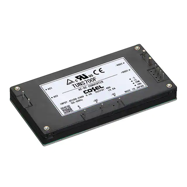
�AC-DC Power Supplies Bus Converter . Power Module Type
TUNS700F
Ordering information
TUN
1
S
2
700
3
F
4
*Avoid short circuit between +BC/R and -BC. It may cause the failure of inside components.
*Keep TRM open, if output voltage adjustment is not necessary.
*If remote sensing is not necessary, connect between +Vout & +S and between -Vout & -S.
TUNS700F12
700.8
12V 58.4A
-O
6
1 Series name
2 Single output
3 Output wattage
4 Universal Input
5 Output voltage
6 Optional
T : with Mounting hole
(f3.4 thru)
Y1: Outputvoltage adjustment
range ±20% (Only 48V)
R1: with Remote ON/OFF
(Negative logic control)
R2: with Remote ON/OFF
(Negative logic and Low standby power)
�
R3: with Remote ON/OFF
(Positive logic control)
P : Parallel operation
(�Output voltage trimming disabled,
Remote sensing disabled)
R
MODEL
MAX OUTPUT WATTAGE[W]
DC OUTPUT
48
5
TUNS700F28
700.0
28V 25A
TUNS700F48
700.8
48V 14.6A
SPECIFICATIONS
MODEL
VOLTAGE[V]
TUNS700F48
POWER FACTOR
(Io=100%)
INRUSH CURRENT
LEAKAGE CURRENT[mA]
VOLTAGE[V]
CURRENT[A]
LINE REGULATION[mV]
LOAD REGULATION[mV]
0 to +100C* 1
RIPPLE[mVp-p]
-40 to 0C *1
0 to +100C *1
OUTPUT
RIPPLE NOISE[mVp-p]
-40 to 0C *1
0 to +65C
TEMPERATURE REGULATION[mV]
-40 to +100C
*2
DRIFT[mV]
OUTPUT VOLTAGE ADJUSTMENT
RANGE[V]
OUTPUT VOLTAGE SETTING[V]
OVERCURRENT PROTECTION
PROTECTION OVERVOLTAGE PROTECTION[V]
CIRCUIT AND
REMOTE SENSING
OTHERS
REMOTE ON/OFF
TUNS700F12
TUNS700F28
AC85 - 264 1f
8.6typ (Io=100%)
4.1typ (Io=100%)
50/60 (47 - 63)
83typ
86typ
86typ
89typ
0.96typ
0.93typ
Limited by external resistance
0.75max (ACIN 240V 60Hz, Io=100%, According to IEC62368-1)
12
28
58.4
25
24max
56max
24max
56max
120max
180max
150max
200max
150max
200max
200max
300max
120max
280max
240max
560max
40max
90max
Fixed (TRM pin open), adjustable by external resistor or external signal
9.60 - 14.40
22.40 - 33.60
11.91 - 12.29
27.56 - 28.44
Works over 105% of rating and recovers automatically
15.00 - 16.80
35.00 - 39.20
Provided
Optional (External power supply is required)
MODEL
MAX OUTPUT WATTAGE[W]
DC OUTPUT
TUNS700F12-P
700.8
12V 58.4A
TUNS700F48-P
700.8
48V 14.6A
CURRENT[A]
ACIN 100V
ACIN 200V
FREQUENCY[Hz]
INPUT
EFFICIENCY[%]
ACIN 100V
ACIN 200V
ACIN 100V
ACIN 200V
TUNS700F28-P
700.0
28V 25A
87typ
90typ
48
14.6
96max
96max
250max
300max
300max
450max
480max
960max
180max
38.40 - 52.80 (-Y1 Option : 38.4 - 57.6)
47.24 - 48.76
55.20 - 64.80 (-Y1 Option : 60.0 - 67.2)
SPECIFICATIONS
MODEL
VOLTAGE[V]
TUNS700F12-P
TUNS700F28-P
AC85 - 264 1f
ACIN 100V 8.6typ (Io=100%)
CURRENT[A]
ACIN 200V 4.1typ (Io=100%)
FREQUENCY[Hz]
50/60 (47 - 63)
ACIN 100V 83typ
86typ
INPUT
EFFICIENCY[%]
ACIN 200V 86typ
89typ
POWER FACTOR
ACIN 100V 0.96typ
(Io=100%)
ACIN 200V 0.93typ
INRUSH CURRENT
Limited by external resistance
LEAKAGE CURRENT[mA] 0.75max (ACIN 240V 60Hz, Io=100%, According to IEC62368-1)
VOLTAGE[V]
12
28
CURRENT[A]
58.4
25
VOLTAGE ACCURACY[%]
+5, -3
+5, -3
0 to +100C *1 240max
360max
OUTPUT
RIPPLE[mVp-p] -40 to 0C *1 300max
400max
0 to +30% Load *1 360max
540max
0 to +100C *1 300max
400max
RIPPLE NOISE[mVp-p] -40 to 0C *1 400max
600max
0 to +30% Load *1 450max
600max
PROTECTION OVERCURRENT PROTECTION Works over 105% of rating and recovers automatically
35.00 - 39.20
CIRCUIT AND OVERVOLTAGE PROTECTION[V] 15.00 - 16.80
REMOTE ON/OFF
Optional (External power supply is required)
OTHERS
TUNS-10
July 13, 2022
TUNS700F48-P
87typ
90typ
48
14.6
+5, -3
600max
700max
900max
700max
1000max
1000max
55.20 - 64.80
�TUNS700F
GENERAL SPECIFICATIONS
*4
INPUT-OUTPUT-RC
INPUT-FG
ISOLATION
*4
OUTPUT-RC-FG
*4
OUTPUT-RC
OPERATING TEMP.,HUMID.AND ALTITUDE
STORAGE TEMP.,HUMID.AND ALTITUDE
ENVIRONMENT
VIBRATION
IMPACT
AGENCY APPROVALS
SAFETY AND
NOISE REGULATIONS HARMONIC ATTENUATOR
CASE SIZE/WEIGHT
OTHERS
COOLING METHOD
AC3,000V 1minute, Cutoff current = 10mA, DC500V 50MW min (20±15C)
AC2,000V 1minute, Cutoff current = 10mA, DC500V 50MW min (20±15C)
AC500V 1minute, Cutoff current = 100mA, DC500V 50MW min (20±15C)
AC100V 1minute, Cutoff current = 100mA, DC100V 10MW min (20±15C)
-40 to +100C (On aluminum base plate), 20 - 95%RH (Non condensing) (Refer to “Derating”), 3,000m (10,000 feet) max
-40 to +100C, 20 - 95%RH (Non condensing), 9,000m (30,000 feet) max
10 - 55Hz, 49.0m/s2 (5G), 3minutes period, 60minutes each along X, Y and Z axis
196.1m/s2 (20G), 11ms, once each along X, Y and Z axis
UL60950-1, C-UL (CSA60950-1), EN62368-1
Complies with IEC61000-3-2 (Class A) *3
117.3X12.7X61.5mm [4.62X0.5X2.42 inches] (WXHXD) / 190g max
Conduction cooling (e.g. heat radiation from the aluminum base plate to the attached heat sink)
*1 �Refer to instruction manual for measuring method of electric characteristics.
*2 Drift is the change in DC output for an eight hour period after a half-hour warm-up at 25C, with the input voltage held constant at the rated input/output.
*3 Please contact us about another class.
*4 ”RC” is applicable when remote control (optional) is added.
Lot No.
Recommending size for processing PCB
(TOP VIEW)
[0.5]
Base Plate (Aluminum)
12.7 ±0.5
External view
11- 1.5
15
15
[0.59] [0.59]
44.05
[1.73]
4- 3.5
10.2 10 9 3×4=12
[0.4] [0.39] [0.35] [0.47]
50.8
[2.0]
5.0
117.3 max
[0.2]
±0.5
Case (PBT)
[4.62]
106.7 ±0.5
[4.2]
(5.3)
2- 2 ±0.2
10 10.2
[0.47] [0.35] [0.39] [0.4]
3×4=12 9
[2.42]
±0.5
[2.0]
50.8
61.5 max
10 10.2
[0.39] [0.4]
[0.21]
2- 2.5
106.7
[4.2]
4
[0.16]
11- 1 ±0.1
15
15
44.05
[0.59]
[0.59]
[1.73]
Control pin for Remote
ON/OFF (Option)
[0.16]
Div. : 0.5inch
[0.21]
4
Name Plate
(5.35)
Dimensions in :
4-M3
Mounting Hole
AC1
-VOUT
AC2
+VOUT
-S, -M (Option : P)
+S, +M (Option : P)
TRM, NC (Option : P)
IOG
R +BC -BC
RC2 (Option : R1/R2)
RC1 (Option : R1/R2)
mm
[inch]
Tolerance : 0.3 [ 0.012]
Weight : 190g max
Dimensions in mm, [ ]=inches
Mounting hole screwing torque : 0.49N m (5.0kgf cm) max
4-FG
July 13, 2022
TUNS-11
�AC-DC Power Supplies Bus Converter . Power Module Type
TUNS1200F
Ordering information
TUN
1
S
2
1200
3
F
4
48
5
-O
6
1 Series name
2 Single output
3 Output wattage
4 Universal Input
5 Output voltage
6 Optional
T : with Mounting hole
(f3.4 thru)
Y1: Outputvoltage adjustment
range ±20% (Only 48V)
R3: with Remote ON/OFF
(Positive logic control)
N1: �Auto restart from thermal
protection
R
*�Avoid short circuit between +BC/R and -BC. It may cause the failure of inside components.
*�Keep VTRM open, if output voltage adjustment is not necessary.
*�Keep ITRM open, if output current adjustment is not necessary.
*�If remote sensing is not necessary, connect between +Vout & +S and between -Vout & -S.
MODEL
MAX OUTPUT WATTAGE[W]
DC OUTPUT
TUNS1200F12
1008
12V 84A
TUNS1200F28
1204
28V 43A
TUNS1200F48
1200
48V 25A
TUNS1200F65
1202.5
65V 18.5A
SPECIFICATIONS
MODEL
VOLTAGE[V]
CURRENT[A]
ACIN 100V
ACIN 200V
FREQUENCY[Hz]
INPUT
OUTPUT
ACIN 100V
ACIN 200V
ACIN 100V
POWER FACTOR (Io=100%)
ACIN 200V
INRUSH CURRENT
LEAKAGE CURRENT[mA]
VOLTAGE[V]
CURRENT[A]
LINE REGULATION[mV]
LOAD REGULATION[mV]
0 to +100C *1
RIPPLE[mVp-p]
-40 to 0C *1
0 to +100C *1
RIPPLE NOISE[mVp-p]
-40 to 0C *1
0 to +80C *1
TEMPERATURE REGULATION[mV]
-40 to +100C *1
*2
DRIFT[mV]
EFFICIENCY[%]
OUTPUT VOLTAGE ADJUSTMENT RANGE[V]
OUTPUT VOLTAGE SETTING[V]
OVERCURRENT PROTECTION
PROTECTION
OVERVOLTAGE PROTECTION[V]
CIRCUIT AND
REMOTE SENSING
OTHERS
REMOTE ON/OFF
INPUT-OUTPUT
INPUT-FG
ISOLATION
OUTPUT-FG
OUTPUT-RC, PG
OPERATING TEMP.,HUMID.AND ALTITUDE
STORAGE TEMP.,HUMID.AND ALTITUDE
ENVIRONMENT
VIBRATION
IMPACT
AGENCY APPROVALS
SAFETY AND
NOISE REGULATIONS
HARMONIC ATTENUATOR
CASE SIZE/WEIGHT
OTHERS
COOLING METHOD
TUNS1200F12
TUNS1200F28
TUNS1200F48
TUNS1200F65
AC85 - 305V 1f
12typ
14typ
14typ
14typ
5.9typ
6.7typ
6.6typ
6.7typ
50/60 (47 - 63)
85typ
89typ
90typ
89typ
87typ
91typ
92typ
91typ
0.98typ
0.95typ
Limited by external resistance
0.5max (ACIN 240V 60Hz, Io=100%, According to IEC60601-1)
12
28
48
65
84
43
25
18.5
24max
56max
96max
130max
24max
56max
96max
130max
150max
180max
250max
350max
180max
200max
300max
400max
180max
200max
300max
400max
200max
300max
450max
450max
120max
280max
480max
650max
240max
560max
960max
1300max
40max
90max
180max
240max
Fixed (VTRM pin open), adjustable by external resistor or external signal
9.60 - 14.40
22.40 - 33.60
38.40 - 52.80 (Y1:38.4 - 57.6) 52.00 - 78.00
11.91 - 12.29
27.56 - 28.44
47.24 - 48.76
63.96 - 66.04
Works over 105% of rating and recovers automatically
15.00 - 16.80
35.00 - 39.20
55.20 - 60.00 (Y1:60.0 - 67.2) 81.25 - 91.00
Provided
Provided
AC3,000V 1minute, Cutoff current = 10mA, DC500V 50MW min (20±15C) 2MOOP
AC2,000V 1minute, Cutoff current = 10mA, DC500V 50MW min (20±15C) 1MOOP
TUNS1200F12/28/48 : AC500V 1minute, Cutoff current = 100mA, DC500V 50MW min (20±15C)
: AC1,200V 1minute, Cutoff current = 10mA, DC500V 50MW min (20±15C) 1MOOP
TUNS1200F65
AC100V 1minute, Cutoff current = 100mA, DC100V 10MW min (20±15C)
-40 to +100C (On aluminum base plate), 20 - 95%RH (Non condensing) (Refer to DERATING CURVE)
-40 to +100C, 20 - 95%RH (Non condensing), 9,000m (30,000 feet) max
10 - 55Hz, 49.0m/s2 (5G), 3minutes period, 60minutes each along X, Y and Z axis
196.1m/s2 (20G), 11ms, once each along X, Y and Z axis
UL62368-1, EN62368-1, C-UL (equivalent to CAN/CSA-C22.2 No.62368-1), ANSI/AAMI ES60601-1, EN60601-1 3rd,
C-UL (equivalent to CAN/CSA-C22.2 No.60601-1), Complies with IEC60601-1-2 4th
Complies with IEC61000-3-2 (Class A) *3
117.3X12.7X86.8mm [4.62X0.5X3.42 inches] (WXHXD) / 280g max
Conduction cooling (e.g. heat radiation from the aluminum base plate to the attached heat sink)
*1 �Refer to instruction manual for measuring method of electric characteristics.
*2 Drift is the change in DC output for an eight hour period after a half-hour warm-up at 25C, with the input voltage held constant at the rated input/output.
*3 Please contact us about another class.
TUNS-12
July 13, 2022
�TUNS1200F
12.7±0.5
[0.5]
Lot No.
[0.2]
Base plate(Aluminum)
5±0.5
External view
Case(PBT)
4-M3(FG)
Mounting Hole
15
15
[0.59]
[0.59]
AC1
2.5
3.5
9-f
[1.3]
10-f
1.5
[3.0]
10
[0.39]
33.1
[0.39]
[0.2]
10 5
4-f
4
[0.16]
[4.2]
¶ Dimensions in :
PGG
RC2
CB
-S
+S
¶ Div. : 0.5inch
mm
[inch]
¶ Tolerance : �0.3 [�0.012]
¶ Weight : 280g max
¶ Dimensions in mm, [ ]=inches
¶ Mounting hole screwing torque : 0.49N-m (5.0kgf-cm) max
-VOUT
AC2
15
106.7
Pin Configuration
PG
RC1
AUX
VTRM
ITRM
15
[0.59] [0.59]
76.2
[0.45]
10
5
10 4x4=16
[0.39] [0.63]
[0.2]
[3.42]
86.8max
34.3
[1.35]
[0.2]
34.3
±0.2
5.05
9-f2
[3.0]
[0.39]
76.2±0.5
10-f1 ±0.1
10
11.45
[0.16]
[1.3]
33.1
Name Plate
[1.35]
Recommending size for processing PCB
(TOP VIEW)
4
[0.45] [0.63] [0.39][0.2]
[4.2]
5
[0.2]
[0.39] [0.2]
[4.62]
106.7±0.5
11.45 4x4=16 10 5
117.3max
5.06
+VOUT
R
+BC
-BC
Bottom View
July 13, 2022
TUNS-13
�TUNS-series
Pin Configuration
¿ TUNS50F
No.
Pin
Function
TUNS50F TUNS100F Connection
1
1
AC1
AC input
2
2
AC2
3
3
+BC
+BC output
4
4
-BC
-BC output
5
5
+VOUT +DC output
7
9
-VOUT -DC output
8
-S
Remote sensing (-)
6
+S
Remote sensing (+)
6
7
TRM
Adjustment of output voltage
FG
Mounting hole (FG)
7-VOUT
6TRM
5+VOUT
1AC1
2AC2
2-FG
3+BC 4-BC
*bottom view
¿ TUNS100F
9-VOUT
1AC1
8-S
7TRM
6+S
2AC2
5+VOUT
4-FG
3+BC 4-BC
*bottom view
¿ TUNS300F/TUNS500F/TUNS700F
1 AC1
7 -VOUT
2 AC2
6 +VOUT
8 -S
9 +S
0 TRM
å IOG
4-FG
3 R 4 +BC 5 -BC
*bottom view
¿ TUNS700FOO-P (OPTION)
1 AC1
7 -VOUT
2 AC2
6 +VOUT
8 -M
9 +M
0 NC
å IOG
4-FG
3 R 4 +BC 5 -BC
No.
1
2
3
4
5
6
7
8
9
0
å
∫
ç
-
Pin
Connection
AC1
AC2
R
+BC
-BC
+VOUT
-VOUT
-S
+S
TRM
IOG
RC1
RC2
FG
Function
AC input
External resistor for inrush current protection
+BC output
-BC output
+DC output
-DC output
Remote sensing (-)
Remote sensing (+)
Adjustment of output voltage
Inverter operation monitor
Remote ON/OFF (Option)
Mounting hole (FG)
Pin
Function
Connection
8
-M
Output voltage monitor terminal
9
+M
0
NC
No connection
Other than the above are the same as standard products.
No.
*bottom view
¿ TUNS1200F
No.
ˆPG
˙RC1
©AUX
ƒVTRM
´ITRM
1AC1
9
-VOUT
8
2AC2
3R 4+BC 5-BC
*bottom view
TUNS-14
∂PGG
çRC2
∫CB
å-S
0+S
7 +VOUT
6
4-FG
1
2
3
4
5
67
89
0
å
∫
ç
∂
´
ƒ
©
˙
ˆ
-
Pin
Connection
AC1
AC2
R
+BC
-BC
+VOUT
-VOUT
+S
-S
CB
RC2
PGG
ITRM
VTRM
AUX
RC1
PG
FG
July 13, 2022
Function
AC input
External resistor for inrush current protection
+BC output
-BC output
+DC output
-DC output
Remote sensing (+)
Remote sensing (-)
Current balance
Remote ON/OFF ground
Power good output ground
Adjustment of output current
Adjustment of output voltage
Auxiliary output
Remote ON/OFF
Power good output
Mounting hole (FG)
�TUNS-series
Implementation・Mounting Method
Mounting method
¡Use with the conduction cooling (e.g. heat dissipation from the aluminum base plate to the attached heat sink).
¡Use a heat sink that larger than the power supply and has a large thickness so that the alminum base plate can be cooled uniformly.
¡The unit can be mounted in any direction. When two or more power supplies are used side by side, position them with proper intervals to
allow enough air ventilation. Aluminum base plate temperature of each power supply should not exceed the temperature range shown in
“derating”.
¡Avoid placing the AC input line pattern layout underneath the unit. It will increase the line conducted noise. Make sure to leave an ample
distance between the line pattern layout and the unit. Also avoid placing the DC output line pattern underneath the unit because it may
increase the output noise. Lay out the pattern away from the unit.
¡Avoid placing the signal line pattern layout underneath the unit because the power supply might become unstable. Lay out the pattern
away from the unit.
¡High-frequency noise radiates directly from the unit to the atmosphere. Therefore, design the shield pattern on the printed circuit board
and connect it to FG or -BC.The shield pattern prevents noise radiation.
¡When a heat sink cannot be fixed on the base plate side, order the power module
with “-T”option. A heat sink can be mounted by affixing a M3 tap on the heat sink.
Please make sure a mounting hole will be connected to a grounding capacitor CY.
Standard
Optional : -T
Mounting hole
M3 tapped
f3.4 thru
¿ TUNS50F/100F/300F/500F/700F
Stress onto the pins
+VOUT, -VOUT
¡When too much stress is applied to the pins may damage internal
connections. Avoid applying stress in excess of that shown in right
Others
figure.
¡The pins are soldered onto the internal PCB.
Therefore, Do not bend or pull the leads with excessive force.
Less than
39.2N(4kgf)
¡Mounting hole diameter of PCB should be 3.5mm to reduce the
stress to the pins.
¡Fix the unit on PCB (fixing fittings) by screws to reduce the stress to
the pins. Be sure to mount the unit first, then solder the unit.
Soldering temperature
: 260C for up to 15 seconds.
¡Flow soldering
¡Soldering iron (26W) : 450Cfor up to 5 seconds.
Less than
39.2N(4kgf)
Less than
19.6N(2kgf)
Less than
19.6N(2kgf)
Less than
19.6N(2kgf)
Less than
39.2N(4kgf)
¿ TUNS1200F
AC1,AC2,R,+BC,-BC,+VOUT,-VOUT
Less than
39.2N(4kgf)
Less than
39.2N(4kgf)
Others
Less than
19.6N(2kgf)
Less than
19.6N(2kgf)
Less than
19.6N(2kgf)
Less than
39.2N(4kgf)
Derating
Input voltage derating curve
¿ TUNS50F/100F
¿ TUNS700F/1200F
*�TUNS1200F12 has no input voltage derating.
Load factor
Load Factor [%]
[%]
100
80
85 90
100
85
85
[AC V]
100
[AC V]
¿ TUNS300F/500F
*�TUNS300F/500F has no input voltage derating.
July 13, 2022
TUNS-15
�TUNS-series
Derating
Output voltage derating curve
¡Use the power modules with conduction cooling (e.g. heat dissipation from the aluminum base plate to the attached heat sink).
�Below shows the derating curves with respect to the aluminum base plate temperature. Note that operation within the hatched areas will
cause a significant level of ripple and ripple noise.
¡Please measure the temperature on the aluminum base plate edge side when you cannot measure the temperature of the center part of
the aluminum base plate.In this case, please take 5deg temperature margin from the derating characteristics shown in below. Please reduce the temperature fluctuation range as much as possible when the up and down of the temperature are frequently generated. Contact
us for more information on cooling methods.
¿ TUNS50F/100F
Load Factor [%]
100
Tc
Measuring point
1
(75)
50
1TUNS50F/TUNS100F
0
-40
-20
0
20
40
(85)
80
60
100
Aluminum base plate temperature Tc [C]
TUNS50F
¿ TUNS300F
¿ TUNS500F
100
1
Load Factor [%]
Load Factor [%]
100
1TUNS300F
50
-20
0
20
40
60
80
Load Factor [%]
100
2
(75)
-20
0
20
40
Tc
Measuring point
1TUNS700F12
2TUNS700F28,TUNS700F48
50
(40)
1
0
-20
0
20
40
(50)
60
(70)
80
100
TUNS300F / TUNS500F / TUNS700F
Aluminum base plate temperature Tc [C]
¿ TUNS1200F
Tc
Measuring point
Load Factor [%]
100
0
-40
3
2
1
(75)
(65)
(60)
50
1 TUNS1200F12
2 TUNS1200F28,TUNS1200F48 (Vin = 85~170VAC),
TUNS1200F65
3 TUNS1200F28,TUNS1200F48 (Vin = 170~305VAC)
-20
0
20
40
60
(85)
80
100
Aluminum base plate temperature Tc [C]
TUNS-16
60
(75)
80
Aluminum base plate temperature Tc [C]
¿ TUNS700F
July 13, 2022
2
1TUNS500F12
2TUNS500F28,TUNS500F48
(60)
50
-40
100
Aluminum base plate temperature Tc [C]
-40
1
0
0
-40
TUNS100F
TUNS1200F
100
�TUNS-series
Instruction Manual
◆ It is neccessary to read the “Instruction Manual” and “Before using our product” before you use our product.
Instruction Manual
https://en.cosel.co.jp/product/powersupply/TUNS/
Before using our product
https://en.cosel.co.jp/technical/caution/index.html
TUNS
NOTICE
Basic Characteristics Data
Model
TUNS50F
TUNS100F
TUNS300F
TUNS500F
TUNS700F
TUNS1200F
Circuit method
Switching
frequency
[kHz]
Active filter
80-600
Flyback converter
100-300
Active filter
80-600
Forward converter
300
Active filter
100
Half-bridge converter
400
Active filter
100
Half-bridge converter
400
Active filter
100
Half-bridge converter
400
Active filter
100
Full-bridge converter
400
Input
current
[A] *1
Inrush
current
protection
circuit
Material
0.67
Thermistor
Aluminum
1.3
Thermistor
3.6
PCB/Pattern
Single Double
sided
sided
Series/Parallel
operation availability
Series
operation
Parallel
operation
Yes
Yes
*2
Aluminum
Yes
Yes
*2
SCR
Aluminum
Yes
Yes
*2
6.0
SCR
Aluminum
Yes
Yes
*2
8.6
SCR
Aluminum
Yes
Yes
*2
14
SCR
Aluminum
Yes
Yes
Yes
*1 The
��
value of input current is at ACIN 100V and rated load.
*2 �Refer to instruction manual.
July 13, 2022
TUNS-17
�