SURFACE MOUNT CERMET TRIMMERS (SINGLE TURN)
RoHS compliant
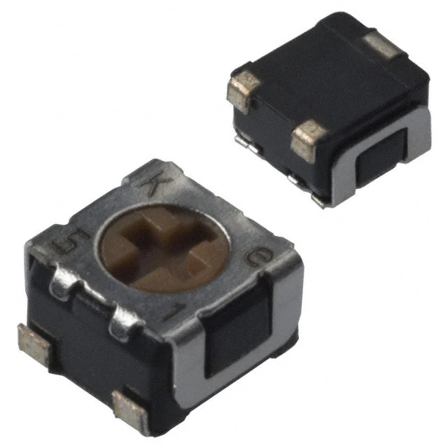
ST-32
INTERNAL STRUCTURE
2
1
7
6
5
3
■ FEATURES
● RoHS compliant
● Rotor with a cross slot for ease of adjustment
● Leaded terminals provide strong as adhesive strength
against P.C.B. bending
● J-hook, Gull wing and leaded terminal configurations
● Sealed (Washable: Refer to page 698.)
● Resin materials are UL Recognized 94V-0 or 94V-1 equivalent
4
9 8
Part name
Material
1
Wiper
Multi metal alloy
2
Cover
Stainless steel (SUS 304)
3
Housing
4
Terminal pin
Copper alloy, Sn-Cu-plated
5
Base element
Ceramic
6
“O” ring
7
Rotor
8
Electrode
Ag-Pd cermet
9
Resistive element
RuO2 cermet
Epoxy
Silicone rubber
PPS
Polyphenylenesulphide
■ PART NUMBER DESIGNATION
S T - 3 2 E T A 1 0 0 Ω ( 1 2 )
Series name
Resistance code
Terminal pin
Resistance value
E:Sn-Cu (Lead-free)
Form of packaging
T:Taping (Reel)
Blank:Bulk in plastic bag
※ Please refer to the LIST OF PART NUMBERS when placing orders.
Product shape (Shape of terminal)
A: J-hook(Top adjustment)
B: Gull wing(Top adjustment)
G:J-hook (Side adjustment)
H:Gull wing(Side adjustment)
�ST-32
SURFACE MOUNT TRIMMERS
■ LIST OF PART NUMBERS
Adjustment Shape of
position
terminal
Top
adjustment
Side
adjustment
)
B (Gull wing)
G ( J-hook )
H (Gull wing)
A ( J-hook
Pieces in package
〈Nominal resistance values〉
Form of packaging
Taping (reel)
Plastic bag
ST-32ETA
ST-32EA
ST-32ETB
ST-32EB
ST-32ETG
ST-32EG
ST-32ETH
ST-32EH
500 pcs./reel
100 pcs./pack
A 10 Ω A 20 Ω 50 Ω 100 Ω 200 Ω 300 Ω 500 Ω
1 kΩ 2 kΩ 3 kΩ 5 kΩ 10 kΩ 20 kΩ 30 kΩ
50 kΩ 100 kΩ 200 kΩ 500 kΩ 1 MΩ 2 MΩ
Fig.1
The products indicated by A mark are manufactured upon receipt of
order basis.
※ The part numbers on the left are all available with the respective combination of
(Fig. 1).
※ Verify the above part numbers when placing orders.
※ Taping specification is not sold separately and must be purchased in reel units.
■ MECHANICAL CHARACTERISTICS
■ ELECTRICAL CHARACTERISTICS
10 Ω ~ 2 MΩ
Nominal resistance range
Resistance tolerance
± 20 %
Power ratings
0.125 W (70 °C) 0 W (125 °C)
Resistance law
Linear law (B)
Maximum input voltage
DC200 V or power rating, whichever is smaller
Maximum wiper current
100 mA or power rating, whichever is smaller
Effective electrical angle
210 ° (1 turn)
End resistance
1 % or 2 Ω , whichever is greater
C.R.V.
1 % or 3 Ω , whichever is greater
− 55 ~ 125 °C
Operating temp. range
Temp. coefficient
Insulation resistance
10 Ω ~ 50 Ω : ± 250 10-6/°C maximum
100 Ω ~ 2 MΩ : ± 100 10-6/°C maximum
1000 MΩ minimum (DC500 V)
Dielectric strength
〈Reflow profile for soldering heat evaluation〉
(°C)
250
250 ° (1 turn)
Operating torque
5 mN·m {51 gf·cm} maximum
Stop strength
20 mN·m {204 gf·cm} minimum
Rotational life
100 cycles [ Δ R/R ≦ ± (2 Ω +3 %)]
Thrust to rotor
5 N {0.51 kgf} minimum
Solderability
245 ± 3 °C, 2 ~ 3 s
Shear (Adhesion)
5 N {0.51 kgf} 10 s
Substrate bending
Width 90 mm, bend 3 mm, 5 s, 1 time
Peak : 250
+5
0
°C
5 N {0.51 kgf} 10 s
Pull-off strength
{ }:Reference only
■ ENVIRONMENTAL CHARACTERISTICS
Test item
Thermal shock
Humidity
Shock
AC500 V, 60 s
Approx. 0.05 g (ST-32EA, EB)
Approx. 0.11 g (ST-32EG, EH)
Net weight
Mechanical angle
Test conditions
Specifications
− 65 ~ 125 °C (0.5 h), 5 cycles
[ Δ R/R ≦ 2 %]
[S.S. ≦ 1 %]
− 10 ~ 65 °C (80 ~ 98 %),
10 cycles, 240 h
981 m/s2, 6 ms
6 directions for 3 times each
Vibration
(Amplitude) 1.52 mm or
(Acceleration) 196 m/s2,
10 ~ 2000 Hz, 3 directions, 12 times each
Load life
70 °C, 0.125 W, 1000 h
[ Δ R/R ≦ 2 %]
[ Δ R/R ≦ 1 %]
[S.S. ≦ 1 %]
[ Δ R/R ≦ 3 %]
[S.S. ≦ 1 %]
[ Δ R/R ≦ 2 %]
[S.S. ≦ 2 %]
[ Δ R/R ≦ 3 %]
[S.S. ≦ 2 %]
Low temp. operation
− 55 °C, 2 h
High temp. exposure
125 °C, 250 h
Immersion seal
85 °C, 60 s
No leaks (No continuous bubbles)
Soldering heat
Flow : 260 ± 3 °C as the temperature in a
pot of molten solder, immersion from head
of terminal to backside of board, 5 ~ 6 s,
two times maximum.
Reflow : Peak temperature 255 °C
(Please refer to the profile below.)
Manual soldering:350 ± 10 °C, 3 ~ 4 s
[ Δ R/R ≦ 1 %]
Temperature
Over 230 °C
200
150
100
50
180 °C
150 °C
Pre Heating Zone
90 ± 30 s
30 ± 10 s
Heating time
Soldering Zone
リフロー回数:2回 Reflow : two times maximum
Δ R/R:Change in total resistance
S.S. :Setting stability
�ST-32
SURFACE MOUNT TRIMMERS
■ MAXIMUM INPUT RATINGS
Nominal resistance
values ( Ω )
Resistance
code
A 10
A 20
Maximum input
voltage (V)
Maximum wiper
current (mA)
11
21
51
12
22
32
52
1.00
1.58
2.50
3.53
5.00
6.12
7.91
100
79.1
50.0
35.4
25.0
20.4
15.8
1 k
2 k
3 k
5 k
10 k
20 k
30 k
50 k
13
23
33
53
14
24
34
54
11.2
15.8
19.4
25.0
35.4
50.0
61.2
79.1
11.2
7.91
6.45
5.00
3.54
2.50
2.04
1.58
100 k
200 k
500 k
1 M
2 M
15
25
55
16
26
112
158
200
200
200
1.12
0.79
0.40
0.20
0.10
50
100
200
300
500
The products indicated by A mark are manufactured upon
receipt of order basis.
■ RECOMMENDED P.C.B. PAD OUTLINE DIMENSIONS
● ST-32EA, EG
● ST-32EB, EH
(Unit : mm)
1.6
0.9
2.2
1.5
1.6
0.9
1
4.6
0
1.2
0.8
1.9
1.2
1
6
0
1.2
3.2
For reflow soldering
1.2
0.8
1.2
3.2
Note) The zero point is the center of mounting.
�ST-32
SURFACE MOUNT TRIMMERS
■ OUTLINE DIMENSIONS
Unless otherwise specified, tolerance : ± 0.3 (Unit : mm)
①
● ST-32EA
Top adjustment
③
CW rotation
②
※ Note the terminal position.
Cross slot for a 0 bit driver, depth : 0.45
Production date code & Lead-free Identification mark
1 digit (Location reversed every 2 years)
1.5
0.5
1
2
3.5
0.6
1.9
3.4
2
0.05
3.4
3
1
Resistance code 2 digits
2
2 – 0.7
t = 0.12
2.1
● ST-32EB
Top adjustment
Cross slot for a 0 bit driver, depth : 0.45
3.4
1
Resistance code 2 digits
2
t = 0.12
2
1.9
0.05
3
1
4.4
Production date code & Lead-free Identification mark
1 digit (Location reversed every 2 years)
1.5
0.5
3.4
2
2.1
2 – 0.7
�ST-32
SURFACE MOUNT TRIMMERS
■ OUTLINE DIMENSIONS
Unless otherwise specified, tolerance : ± 0.3 (Unit : mm)
①
● ST-32EG
Side adjustment
③
CW rotation
②
※ Note the terminal position.
Cross slot for a 0 bit driver, depth : 0.45
Production date code & Lead-free Identification mark
1 digit (Location reversed every 2 years)
Adjustment
3.6
1.5
0.5
3
3.5
1
2.4
2 – 0.6
1.7
1.1
2.6
1.9
4.7
1
0.2
1
t = 0.12
Resistance code 2 digits
2
● ST-32EH
Side adjustment
Cross slot for a 0 bit driver, depth : 0.45
3.6
1.5
Production date code & Lead-free Identification mark
1 digit (Location reversed every 2 years)
0.5
3
3.5
2.4
1
2 – 0.6
1.7
1.3
2.6
1.9
4.7
1.4
0.2
Adjustment
Resistance code 2 digits
t = 0.12
1
2
�ST-32
SURFACE MOUNT TRIMMERS
■ PACKAGING SPECIFICATIONS
● Taping version is packaged in 500 pcs. per reel.
Orders will be accepted for units of 500 pcs., i.e., 500, 1000, 1500 pcs., etc.
● ST-32ETA, ETB versions are boxed with 4 reels (2000 pcs.). ST-32ETG, ETH versions are boxed with one reel (500 pcs.).
Maximum number of consecutive missing pieces = 2
Leader length and reel dimension are shown in the diagrams below.
● EMBOSSED TAPE DIMENSIONS
● REEL DIMENSIONS
(Conforms to JIS C 0806-3)
(In accordance with EIAJ ET-7200A)
Empty
Filled
(Unit: mm)
Empty
Head
φ 21±0.8
40 mm min.
φ 60 +10 (ETA/ETB)
φ 50 min.(ETG/ETH)
End
13 +10 (ETA/ETB)
13.4±1 (ETG/ETH)
2±0.5
20 pitches min.
Leader
400 mm min.
Direction of feed
φ 13±0.2
15.4±1 (ETA/ETB)
17.4±1 (ETG/ETH)
0
(ST-32ETA/ETB)
φ 180 –1.5
φ 254±2 (ST-32ETG/ETH)
● ST-32ETA, ETB
● ST-32ETG, ETH
8±0.1
4±0.1
5.5±0.1
12
5.5±0.05
.1
+0 0
2
Installation example
(ST-32EA)
2.5
3
1
3
● Unit of bulk in a plastic bag is 100 pcs. per pack.
● Boxing of bulk in a plastic bag is performed with
500 pcs. per box.
0.4±0.1 Installation example
(ST-32EH)
1
5.5 max.
Direction of feed
Direction of feed
1.75±0.1
8±0.1
2±0.1
.5
φ1
.1
+0 0
.5
φ1
2
0.3±0.1
12
2±0.05
1.75±0.1
4±0.1
�


 工商网监
湘ICP备2023018690号
工商网监
湘ICP备2023018690号
