Confidential
Ver. 2.0 Preliminary
160A-M
4/3-Type, 16.78-mega pixel CMOS Image Sensor
The specifications are subject to change without notice.
General Description
The 160A-M is a 4/3-type 16.78-megapixel high resolution CMOS image sensor, the frame rate is up to 46.8fps at
full resolution of 4096 (H) x 4096 (V). Sensors is featured with global shutter pixels, high-resolution ADC and highspeed readout. The sensors meet the high-performance and high-resolution requirements in applications such as
intelligent traffic system, machine vision and high-resolution industrial inspection, etc.
Features
• Active pixel array
160A-M 4112 (H) × 4112 (V)
14.34mm (H) × 14.34 mm (V), 20.27mm
• Global shutter pixel
• Programmable analog gain and digital gain
• 14-bit ADC
• Master mode, Slave mode and TRIGEXP mode
• External electronic shutter control (only in TRIGEXP mode)
• Other functions
Multi-ROI (V-direction only)
Vertical/Horizontal binning
Vertical/Horizontal sub-sampling
Vertical/Horizontal normal and inverted readout mode
Specifications
Applications
Table 1. Sensor specifications
Parameters
Specifications
160A-M:
Image Format
20.27mm
4/3-Type,
Number of Total Pixels
160A-M: 4336 (H) x 4184
(V)
Number of Active Pixels
160A-M: 4112 (H) x 4112
(V)
Pixel Size
Pixel Type
Sensitivity
Saturation (Linear)
Dynamic Range
Read noise (with Pixel)
Windowing (ROI)
ADC Resolution
Frame Rate
LVDS Outputs
Data Rate
Power Supply
Power Consumption
Chroma
Type of Package
diagonal
• Intelligent traffic system
• Machine vision
• High resolution industrial inspection
3.5μm x 3.5μm
Global shutter pixel
T.B.D. (> 2V/lux∙s)
T.B.D. (> 0.9V)
T.B.D.
T.B.D.
V-direction only with multi-ROI
14bit
Maximum frame rate at full
resolution 160A-M: 46.8fps
16 LVDS pairs
Max. 800 Mbps/pair
1.2V/1.8V/3.3V
T.B.D
Mono
and Color
※
230
WWpin LGA
1 / 45
�4/3-Type, 16.78-Mpix CMOS Image Sensor
Contents
General Description ..................................................................................................................................................................................... 1
Features ........................................................................................................................................................................................................ 1
Specifications ................................................................................................................................................................................................ 1
Applications .................................................................................................................................................................................................. 1
Block Diagram ............................................................................................................................................................................................... 3
Pixel Array ..................................................................................................................................................................................................... 4
Pin Arrangement .......................................................................................................................................................................................... 6
Pin Descriptions ............................................................................................................................................................................................ 7
Peripheral Connections .............................................................................................................................................................................. 12
Absolute Maximum Ratings ....................................................................................................................................................................... 13
DC Electrical characteristics ....................................................................................................................................................................... 13
AC Electrical characteristics ....................................................................................................................................................................... 15
Internal Register Access ............................................................................................................................................................................. 20
Internal Register Access ..................................................................................................................................................................... 20
Register Reflection Timing ................................................................................................................................................................. 22
Register Map .............................................................................................................................................................................................. 23
Input Signals ............................................................................................................................................................................................... 24
Master Mode and Salve Mode .......................................................................................................................................................... 24
Input Signals ....................................................................................................................................................................................... 24
Input Reference Clock and Clock System .......................................................................................................................................... 24
Synchronize Signal ............................................................................................................................................................................. 27
Frame Rate and Output Data Rate ............................................................................................................................................................ 27
Image Data Output Format ........................................................................................................................................................................ 28
Pixel Read Out Order ......................................................................................................................................................................... 28
Image Output Data Format ............................................................................................................................................................... 28
Sync Code ........................................................................................................................................................................................... 30
Example Data Output of One LVDS Pair ............................................................................................................................................ 32
LVDS Data Bit Output Order .............................................................................................................................................................. 35
Exposure time Adjustment ........................................................................................................................................................................ 36
Internal Expsoure Time Control Mode.............................................................................................................................................. 36
External Exposure Time Control Mode ............................................................................................................................................. 37
Various Function Description..................................................................................................................................................................... 38
Windowing ......................................................................................................................................................................................... 38
Gain..................................................................................................................................................................................................... 39
Test Pattern ........................................................................................................................................................................................ 40
LVDS Receiver Training Code Output ................................................................................................................................................ 40
Vertical/Horizontal Binning ................................................................................................................................................................ 40
Vertical/Horizontal Sub-sampling...................................................................................................................................................... 41
Vertical/Horizontal - Normal/Inverted readout................................................................................................................................. 42
WDR mode ......................................................................................................................................................................................... 42
Other Functions ................................................................................................................................................................................. 42
Power-On Sequence ................................................................................................................................................................................... 43
Spectrum Response ................................................................................................................................................................................... 44
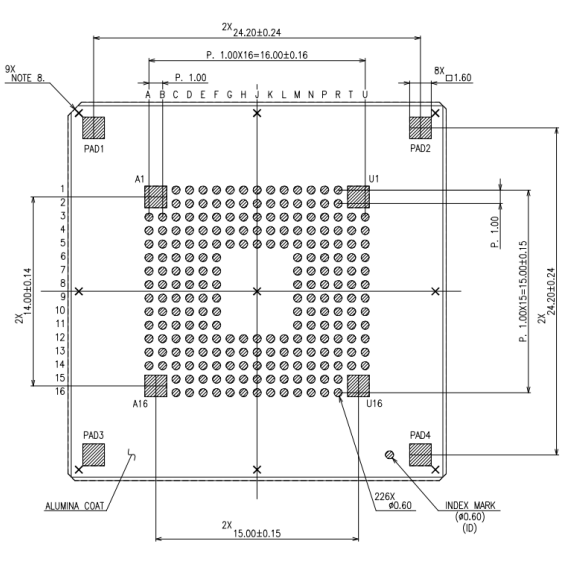
Package ....................................................................................................................................................................................................... 44
Document History ...................................................................................................................................................................................... 45
160A-M
Datasheet Ver. 2.0
Confidential
2 / 45
�4/3-Type, 16.78-Mpix CMOS Image Sensor
Block Diagram
Figure 1. Block Diagram
160A-M
Datasheet Ver. 2.0
Confidential
3 / 45
�4/3-Type, 16.78-Mpix CMOS Image Sensor
Pixel Array
Figure 2. 160A-M Pixel Array
160A-M
Datasheet Ver. 2.0
Confidential
4 / 45
�4/3-Type, 16.78-Mpix CMOS Image Sensor
PIXOUTL[4335]
PIXOUTR[4335]
PIXOUTL[4334]
PIXOUTR[4334]
PIXOUTL[1]
PIXOUTR[1]
PIXOUTL[0]
PIXOUTR[0]
Pixel arrangement at corners
B
G
B
B
G
B
4182
G
R
R
G
R
R
4181
B
G
B
B
G
B
4180
G
R
R
G
R
R
4180
3
B
G
B
B
2
G
R
R
1
B
G
B
0
G
R
R
Pixel arrangement
at top left corner
Pixel Array
4336 H x 4184 V
Pixel arrangement at
bottom right corner
4182
4181
G
B
3
G
R
R
2
B
G
B
1
G
R
R
0
PIXOUTL[4334]
PIXOUTR[4334]
Pixel arrangement at
bottom left corner
4183
PIXOUTL[4335]
PIXOUTR[4335]
Pixel arrangement
at top right corner
PIXOUTL[1]
PIXOUTR[1]
PIXOUTL[0]
PIXOUTR[0]
4183
Figure 4. Pixel arrangement at corner
PIXOUTL[4335]
PIXOUTR[4335]
PIXOUTL[4334]
PIXOUTR[4334]
PIXOUTL[1]
PIXOUTR[1]
PIXOUTL[0]
PIXOUTR[0]
Pixel arrangement at center
B
G
B
B
G
B
2095
2094
G
R
R
G
R
R
2094
2093
B
G
B
B
G
B
2093
2092
G
R
R
G
R
R
2092
2091
B
G
B
B
2090
G
R
R
2089
B
2088
G
R
Pixel Array
4336 H x 4184 V
R
2090
G
B
B
G
B
2089
R
G
R
R
2088
PIXOUTL[4335]
PIXOUTR[4335]
2091
Pixel
arrangement at
vertical center
PIXOUTL[4334]
PIXOUTR[4334]
G
B
G
R
Pixel
arrangement at
vertical center
PIXOUTL[1]
PIXOUTR[1]
PIXOUTL[0]
PIXOUTR[0]
2095
Figure 5. Pixel arrangement at vertical center
160A-M
Datasheet Ver. 2.0
Confidential
5 / 45
�4/3-Type, 16.78-Mpix CMOS Image Sensor
Pin Arrangement
U
1
NC
T
U1
2
R
P
N
M
L
K
J
H
G
F
E
NC
DTSTL0 VSYNC
VDD12
T
SDO
SA
VDD12
VDD12
VSS12T
TOUT0 DTSTR0
T
T
NC
DTSTL1 HSYNC VSS12T
CSN
NC
VSS12T VSS12T VSS12T TOUT2 DTSTR1
D
C
NC6
NC
B
A
NC
A1
VDD12
VNSUB
T
3
NC
TXDN6
TXDP6
NC
TRGEXP
SDI
SCK
SYSRST
SYSSTB
MSTSLV
TOUT1
N
N
NC
NC
VSSR
VSSR
4
TXDN4
TXDP4
TXDN2
TXDP2
NC
VSSA1
VSSP
VSSA1
VSSA1
VSSP
VSSP
NC
VSSP
NC
VSSR
VDDR VRA0_T
5
TXCN1
TXCP1
TXDN0
TXDP0 VSS18L VDDA1
VDDP
NC
VDDA1
VDDP
VDDP
VDDCH
VSSP
NC
VSSR
VDDR VRA1_T
6
TXDN1
TXDP1
TXDN3
TXDP3 VSS18L VSS12L
TX2H
VSSP
RSL
VDDCL
NC
VRA2_T
7
TXDN5
TXDP5
TXDN7
TXDP7 VSS18L VDD18
RSH
VSSP
VSSR
VIREF
TX1L
VSSR
8
VSS12L
ATST2
VSS18L VSS18L VDD18L VSS12L
TX1H
VSSP
VSSR
VSSR
TX2L
GRSTL
GRSTH
VSSP
ATSTIN
VSSR
VDDR
VSSR
NC
VSSP
VSSCP
VCP1
ATST1 VRA2_B
VDDP
VSSP
VSSCP VCP1IN ATST0 VRA1_B
NC
VRP_T
Top View
9
INCLK
NC
VSS18L VSS18L VDD18L VDD12L
VDD12
D
10
TXDN12 TXDP12 TXDN14 TXDP14 VSS18L
11
TXDN8
TXDP8 TXDN10 TXDP10 VSS18L VSS12D
12
TXCN2
TXCP2
13
TXDN13 TXDP13 TXDN11 TXDP11
14
15
16
NC
TXDN9
U16
NC
VDDP
VDDA2
NC
NC
VR_EXT VR_EXT
S
R
VCP2
VSSCP VDDCP VRA0_B
NC
VSSA2
NC
VSSP
VSSA2
VSSA2
NC
NC
NC
VCP2IN
NC
NC
VRP_B
NC2
NC3
NC
NC
NC
NC
NC
NC
NC
VDD12
CP
VSSCP
VSSCP
NC
NC
NC1
DTSTL4
NC4
VSS12B
NC
VSS12B
NC
VSS12B
NC
VSS12B DTSTR4
RCK2
DTSTL3
NC5
VDD12
B
NC
VDD12
B
NC
VDD12
B
NC
VDD12
DTSTR3
B
TXDN15 TXDP15
NC
TXDP9 VSS18L VDDA2
VDD12
VDDCP
CP
NC
NC
A16
NC
Figure 6. Package pin arrangement (Top View)
160A-M
Datasheet Ver. 2.0
Confidential
6 / 45
�4/3-Type, 16.78-Mpix CMOS Image Sensor
Pin Descriptions
#
1
2
3
4
5
6
7
8
9
10
11
12
13
14
15
16
17
18
PIN#
A1
A3
A4
A5
A6
A7
A8
A9
A10
A11
A12
A13
A14
A16
B3
B4
B5
B6
I/O
I
I
I
I
GND
I
GND
I
I
I
I
PWR
PWR
-
A/D
A
A
A
A
A
A
A
A
A
A
A
A
A
-
PIN Function
NC
VRP_T
VRA0_T
VRA1_T
VRA2_T
VSSR
GRSTL
VSSR
VRA2_B
VRA1_B
VRA0_B
VRP_B
NC
NC
NC
VDDR
VDDR
NC
19
B7
I/O
A
TX1L
20
B8
I/O
A
TX2L
21
22
23
24
25
26
27
28
29
30
31
B9
B10
B11
B12
B13
B14
C1
C2
C3
C4
C5
PWR
O
O
PWR
PWR
GND
GND
GND
A
A
A
A
A
A
A
A
VDDR
ATST1
ATST0
VDDCP
NC
NC
NC
VNSUB
VSSR
VSSR
VSSR
32
C6
GND
A
VDDCL
33
34
35
C7
C8
C9
O
GND
GND
A
A
A
VIREF
VSSR
VSSR
36
C10
O
A
VCP1
37
38
39
40
41
42
43
44
45
C11
C12
C13
C14
C15
C16
D1
D2
D3
I
GND
GND
PWR
PWR
GND
A
A
A
A
D
A
VCP1IN
VSSCP
NC
VSSCP
VDDCP
NC
NC
VDD12T
VSSR
160A-M
Datasheet Ver. 2.0
Description
Voltage reference input for read-out circuits
Voltage reference input for read-out circuits
Voltage reference input for read-out circuits
Voltage reference input for read-out circuits
3.3V analog ground
Pixel driving signal low level voltage power supply
3.3V analog ground
Voltage reference input for read-out circuits
Voltage reference input for read-out circuits
Voltage reference input for read-out circuits
Voltage reference input for read-out circuits
3.3V analog power supply
3.3V analog power supply
Pixel driving signal low level voltage power supply,
connect to 10uF+0.1uF to GND
Pixel driving signal low level voltage power supply,
connect to 10uF+0.1uF to GND
3.3V analog power supply
analog test output
analog test output
3.3V analog power supply
Chip substrate potential, 3.3V.
3.3V analog ground
3.3V analog ground
3.3V analog ground
Pixel driving signal low level voltage power supply,
connect to 2.2uF+0.1uF to GND
Connect to analog ground through a 62k resistance.
3.3V analog ground
3.3V analog ground
charge pump output,connect to VCP1IN and 22uF+0.1uF
to GND
LDO power supply, connect to VCP1
3.3V analog ground
3.3V analog ground
3.3V analog power supply
Digital power supply, 1.2V
3.3V analog ground
Confidential
7 / 45
�4/3-Type, 16.78-Mpix CMOS Image Sensor
46
47
48
49
50
51
52
53
D4
D5
D6
D7
D8
D9
D10
D11
-
-
GND
GND
I
GND
GND
A
A
A
D
D
NC
NC
RSL
VSSR
VSSR
ATSTIN
VSSCP
VSSCP
54
D12
O
A
VCP2
55
56
57
58
59
60
61
62
63
64
65
66
67
68
69
70
71
72
73
74
75
76
77
78
79
D13
D14
D15
D16
E1
E2
E3
E4
E5
E6
E7
E8
E9
E10
E11
E12
E13
E14
E15
E16
F1
F2
F3
F4
F5
I
GND
PWR
O
O
GND
GND
GND
GND
GND
GND
GND
GND
I
PWR
O
O
O
O
PWR
A
D
D
D
D
A
A
A
A
A
A
A
A
A
D
D
D
D
D
A
VCP2IN
VSSCP
VDD12CP
NC
DTSTR0
DTSTR1
NC
VSSP
VSSP
VSSP
VSSP
VSSP
VSSP
VSSP
VSSP
VR_EXTR
NC
VDD12CP
DTSTR4
DTSTR3
TOUT0
TOUT2
NC
NC
VDDCH
80
F6
PWR
A
TX2H
81
F7
PWR
A
RSH
82
F8
PWR
A
TX1H
83
F9
PWR
A
GRSTH
84
85
86
87
88
89
90
91
92
93
F10
F11
F12
F13
F14
F15
F16
G1
G2
G3
PWR
I
GND
PWR
PWR
GND
O
A
A
D
D
D
D
D
NC
VDDP
VR_EXTS
NC
NC
VSS12B
VDD12B
VDD12T
VSS12T
TOUT1
160A-M
Datasheet Ver. 2.0
Pixel driving signal low level voltage power supply
3.3V analog ground
3.3V analog ground
Test pin. Leave this pin open
Digital ground
Digital ground
charge pump output,connect to VCP2IN and 22uF+0.1uF
to GND
LDO power supply, connect to VCP2
Digital ground
Digital power supply, 1.2V
Digital test output
Digital test output
3.3V analog ground
3.3V analog ground
3.3V analog ground
3.3V analog ground
3.3V analog ground
3.3V analog ground
3.3V analog ground
3.3V analog ground
Test pin. Leave this pin open.
Digital power supply, 1.2V
Digital test output
Digital test output
Pulse output. High during pixel exposure period.
Leave this pin open if not use.
Pixel driving signal high level voltage power supply
Pixel driving signal high level voltage power supply,
connect to 2.2uF+0.1uF to GND
Pixel driving signal high level voltage power supply,
connect to 2.2uF+0.1uF to GND
Pixel driving signal high level voltage power supply,
connect to 4.7uF+0.1uF to GND
Pixel driving signal high level voltage power supply,
connect to 2.2uF+0.1uF to GND
3.3V analog power supply
Test pin. Leave this pin open.
Digital ground
Digital power supply, 1.2V
Digital power supply, 1.2V
Digital ground
Leave this pin open if not use.
Confidential
8 / 45
�4/3-Type, 16.78-Mpix CMOS Image Sensor
94
95
96
97
98
99
100
101
102
103
104
105
106
107
108
109
110
111
112
113
114
115
116
117
118
119
120
G4
G5
G12
G13
G14
G15
G16
H1
H2
H3
H4
H5
H12
H13
H14
H15
H16
J1
J2
J3
J4
J5
J12
J13
J14
J15
J16
GND
PWR
GND
GND
I
GND
PWR
GND
GND
PWR
PWR
GND
I
GND
PWR
PWR
GND
-
A
A
D
D
D
A
A
A
D
D
D
D
D
A
A
A
A
-
VSSP
VDDP
NC
NC
NC
NC
NC
VSS12T
VSS12T
SYSSTBN
VSSP
VDDP
NC
VSSA2
NC
VSS12B
VDD12B
VDD12T
VSS12T
MSTSLV
VSSA1
VDDA1
VDDA2
VSSA2
NC
NC
NC
121
K1
I
D
SA
122
123
124
125
126
127
128
129
130
131
K2
K3
K4
K5
K12
K13
K14
K15
K16
L1
I
GND
PWR
GND
GND
PWR
O
D
A
A
A
D
D
D
NC
SYSRSTN
VSSA1
NC
VDDP
VSSP
NC
VSS12B
VDD12B
SDO
132
L2
I
D
CSN
133
134
135
136
137
138
139
140
141
142
143
L3
L4
L5
L12
L13
L14
L15
L16
M1
M2
M3
I
GND
PWR
PWR
GND
I
D
A
A
D
D
D
SCK
VSSP
VDDP
NC
NC
NC
NC
NC
VDD12T
VSS12T
SDI
160A-M
Datasheet Ver. 2.0
3.3V analog ground
3.3V analog power supply
Digital ground
Digital ground
System standby signal, low active
3.3V analog ground
3.3V analog power supply
3.3V analog ground
Digital ground
Digital power supply, 1.2V
Digital power supply, 1.2V
Digital ground
Master/Slave selection input. Low: Master, High: Slave.
3.3V analog ground
3.3V analog power supply
3.3V analog power supply
3.3V analog ground
change slave address for 2-wire serial communication
interface
System reset signal. Low active.
3.3V analog ground
3.3V analog power supply
3.3V analog ground
Digital ground
Digital power supply, 1.2V
Serial interface data output.
Serial interface control signal. Pull low to enable the 4wire serial communication.
Serial interface clock input
3.3V analog ground
3.3V analog power supply
Digital power supply, 1.2V
Digital ground
Serial interface data input
Confidential
9 / 45
�4/3-Type, 16.78-Mpix CMOS Image Sensor
144
145
146
147
148
149
150
151
152
153
154
155
156
157
158
159
160
161
162
163
164
165
166
167
168
169
170
171
172
173
174
175
176
177
178
179
180
181
182
183
184
185
186
187
188
189
190
191
192
193
194
M4
M5
M6
M7
M8
M9
M10
M11
M12
M13
M14
M15
M16
N1
N2
N3
N4
N5
N6
N7
N8
N9
N10
N11
N12
N13
N14
N15
N16
P1
P2
P3
P4
P5
P6
P7
P8
P9
P10
P11
P12
P13
P14
P15
P16
R1
R2
R3
R4
R5
R6
160A-M
Datasheet Ver. 2.0
GND
PWR
GND
PWR
GND
PWR
PWR
GND
PWR
GND
GND
PWR
I/O
I/O
I
GND
GND
GND
PWR
PWR
GND
GND
GND
O
O
O
O
O
O
GND
GND
O
O
O
O
O
O
O
O
O
O
A
A
D
D
D
D
D
D
A
A
D
D
D
D
D
D
D
D
D
D
D
D
D
D
D
D
D
D
D
D
D
D
D
D
D
D
D
D
D
D
D
VSSA1
VDDA1
VSS12L
VDD18
VSS12L
VDD12L
VDD12D
VSS12D
VDDA2
VSSA2
NC
VSS12B
VDD12B
VSYNC
HSYNC
TRGEXP
NC
VSS18L
VSS18L
VSS18L
VDD18L
VDD18L
VSS18L
VSS18L
VSS18L
NC
NC
NC
NC
DTSTL0
DTSTL1
NC
TXDP2
TXDP0
TXDP3
TXDP7
VSS18L
VSS18L
TXDP14
TXDP10
TXDP9
TXDP11
NC
DTSTL4
DTSTL3
NC
NC
TXDP6
TXDN2
TXDN0
TXDN3
3.3V analog ground
3.3V analog power supply
Digital ground
I/O power supply,1.8V
Digital ground
Digital power supply, 1.2V
Digital power supply, 1.2V
Digital ground
3.3V analog power supply
3.3V analog ground
Digital ground
Digital power supply, 1.2V
Vertical sync signal input
Horizontal sync signal input
Trigger input
1.8V LVDS Digital ground
1.8V LVDS Digital ground
1.8V LVDS Digital ground
Digital power supply, 1.8V
Digital power supply, 1.8V
1.8V LVDS Digital ground
1.8V LVDS Digital ground
1.8V LVDS Digital ground
Digital test output
Digital test output
LVDS data output
LVDS data output
LVDS data output
LVDS data output
1.8V LVDS Digital ground
1.8V LVDS Digital ground
LVDS data output
LVDS data output
LVDS data output
LVDS data output
Digital test output
Digital test output
LVDS data output
LVDS data output
LVDS data output
LVDS data output
Confidential
10 / 45
�4/3-Type, 16.78-Mpix CMOS Image Sensor
195
196
197
198
199
200
201
202
203
204
205
206
207
208
209
210
211
212
213
214
215
216
217
218
219
220
221
222
223
224
225
226
227
228
229
230
R7
R8
R9
R10
R11
R12
R13
R14
R15
R16
T3
T4
T5
T6
T7
T8
T9
T10
T11
T12
T13
T14
U1
U3
U4
U5
U6
U7
U8
U9
U10
U11
U12
U13
U14
U16
160A-M
Datasheet Ver. 2.0
O
GND
GND
O
O
O
O
O
O
O
O
O
O
O
O
O
O
O
O
O
O
O
O
O
GND
I
O
O
O
O
-
D
D
D
D
D
D
D
D
D
D
D
D
D
D
A
D
D
D
D
D
D
D
D
D
D
D
D
D
D
D
-
TXDN7
VSS18L
VSS18L
TXDN14
TXDN10
TXDN9
TXDN11
TXDP15
NC
RCK2
TXDN6
TXDP4
TXCP1
TXDP1
TXDP5
ATST2
NC
TXDP12
TXDP8
TXCP2
TXDP13
TXDN15
NC
NC
TXDN4
TXCN1
TXDN1
TXDN5
VSS12L
INCLK
TXDN12
TXDN8
TXCN2
TXDN13
NC
NC
LVDS data output
1.8V LVDS Digital ground
1.8V LVDS Digital ground
LVDS data output
LVDS data output
LVDS data output
LVDS data output
LVDS data output
Internal clock output. Half of the internal reference clock.
LVDS data output
LVDS data output
LVDS clock output
LVDS data output
LVDS data output
Analog test output
LVDS data output
LVDS data output
LVDS clock output
LVDS data output
LVDS data output
LVDS data output
LVDS clock output
LVDS data output
LVDS data output
Digital ground, 1.2V
Input reference clock
LVDS data output
LVDS data output
LVDS clock output
LVDS data output
-
Confidential
11 / 45
�4/3-Type, 16.78-Mpix CMOS Image Sensor
Peripheral Connections
3.3V
VDDR/VDDA1/VDDA2/VNSUB
100uF
10uF
0.1uF
VSSR/VSSA1/VSSA2
1.2V
VDD12CP
100uF
3.3V
10uF
VDDCP
100uF
10uF
0.1uF
100uF
VDDP
0.1uF
VSSCP
VDD18
VSS18
1.8V
10uF
10uF
0.1uF
VDD18L
160A-M
VDD12T/VDD12B/VDD12D
10uF
0.1uF
VSS12T/VSS12B/VSS12D
TX1H (3.6V)
TX1L (-1.3V)
4.7+0.1uF
10+0.1uF
1.2V
2.2+0.1uF
VDD12L
100uF
10uF
0.1uF
10+0.1uF
VSS12L
2.2+0.1uF
10+0.1uF
VCP1
22uF
2.2+0.1uF
0.1uF
4.7+0.1uF
VSSCP
VCP1IN
0.1uF
VSSCP
VCP2IN
2.2+0.1uF
100uF
0.1uF
0.1uF
10uF
0.1uF
VDDCH (3.3V)
VDDCL (0.7V)
SYSRSTN
VSSCP
SYSSTBN
VSSCP
0.1uF
VRA2_T
0.1uF
0.1uF
VSSR
TOUT0
INCLK
RCK2
DTSTL0
DTSTL1
DTSTL3
DTSTL4
DTSTR0
DTSTR1
DTSTR3
DTSTR4
VRA1_T
0.1uF
VSSR
VRA0_T
22uF
SW
VSSR
VRA0_B
22uF
TRIGEXP
VRA2_B
100uF
VSSR
MSTSLV
VSSCP
VSSR
100uF
VSSR
CSN
SCK
SDI
SDO
VSYNC
HSYNC
TX2H (3.6V)
TX2L (-1.3V)
VSSR
VRA1_B
100uF
VSSCP
VRP_T
VRP_B
10uF
VSSCP
GRSTH (4.1V)
GRSTL (-0.5V)
RSH (4.1V)
RSL (0V)
2.2+0.1uF
VCP2
22uF
ISP
VSS18L
VSSP
1.2V
100uF
TXCP1/N1
0.1uF
3.3V
100uF
LVDS LT
0.1uF
1.8V
VSSCP
TXDP/N[15:1:2]
TXCP2/N2
TXDP/N[14:0:2]
0.1uF
VSSR
LVDS LB
Figure 7. Peripheral connections
160A-M
Datasheet Ver. 2.0
Confidential
12 / 45
�4/3-Type, 16.78-Mpix CMOS Image Sensor
Absolute Maximum Ratings
Table 2. Absolute maximum ratings
T.B.D (-10 ~ 60 ℃)
T.B.D (-40 ~ 85 ℃)
VDD33, VDDP33, VDDCP33
-0.3V ~ 4.6V
Supply voltage
VDD18, DVDD18L
-0.3V ~ 3.3V
(with respect to ground)
VDD12, VDD12L, VDD12CP
-0.3V ~ 1.7V
Digital I/O (DIO/DI/DO. With respect to ground.)
-0.3V ~ VDD18 + 0.3V but