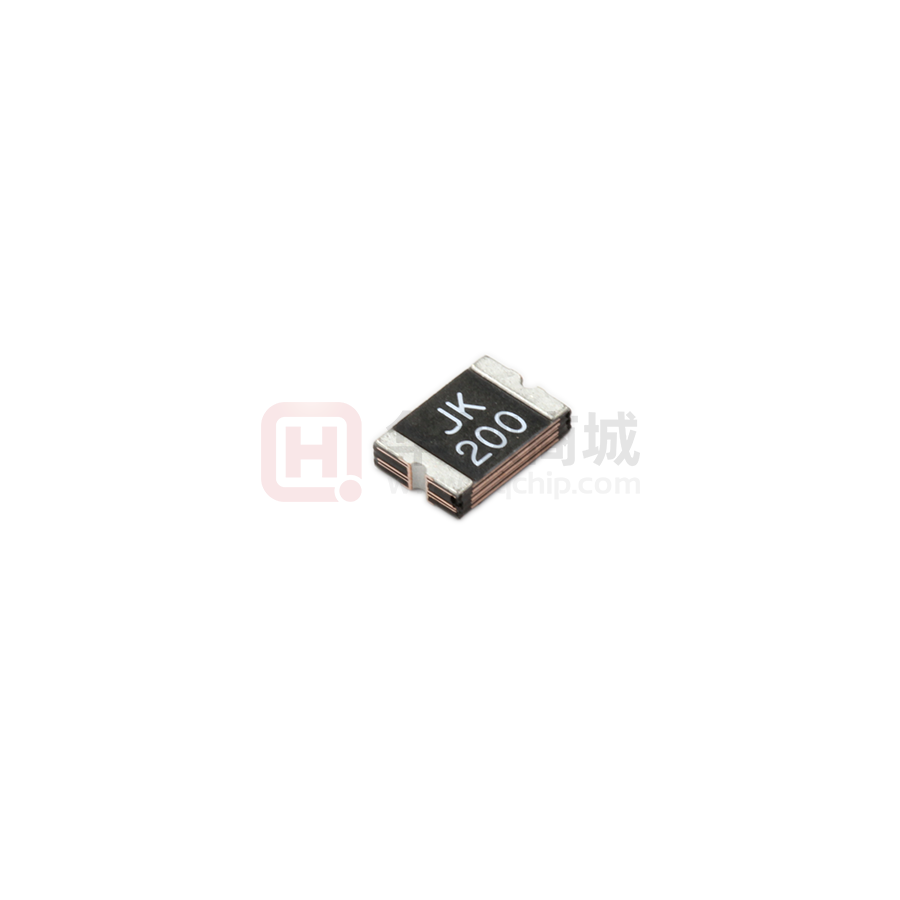
JK-mSMD200
PPTC DEVICES
Edition:A0
Part Number:Q/JKTD-24-200
Page No: 1 OF 3
Terminal pad materials :Tin-Plated Nickle-copper
Terminal pad solderability : Meets EIA specification
RS 186-9E and ANSI/J-STD-002 Category 3.
Marking : JK200=1812(200)
Table1 :DIMENTION(Unit : mm)
Model
Marking
JK-mSMD200
JK200
A
B
C
D
E
Min.
Max.
Min.
Max.
Min.
Max
Min.
Min
4.37
4.73
3.07
3.41
0.80
1.60
0.30
0.25
Table2 :PERFORMANCE RATINGS:
Model
Vmax
(Vdc)
Imax
(A)
Ihold
@25℃
(A)
JK-mSMD200
24
100
2.00
Itrip
@25℃
(A)
Pd
Typ
(W)
4.00
0.8
Maximum
Resistance
Time To Trip
Current
(A)
Time
(Sec)
Rimin
(Ω)
Rityp
(Ω)
R1max
(Ω)
8.0
2.00
0.020
0.032
0.120
Table3:Test Conditons and Standards
Item
Initial Resistance
IH
Ttrip
.trip
Trip endurance
Operating Temperature:-40℃ TO
Packaging:Bulk ,1500pcs per bag
Test Conditon
25℃
25℃,2.00A, 60min
25℃,8.0A
24V,100A, 1hr
Standard
0.020~0.120Ω
No Trip
≤2.00s
No arcing or burning
85℃
E-mail:customer@jkpptc.com
�JK-mSMD200
PPTC DEVICES
Part Number:Q/JKTD-24-200
Edition:A0
Page No: 2 OF 3
Solder reflow conditions
● Recommended reflow methods: IR, vapor phase
oven, hot air oven, N2 environment for lead-free.
● Devices are not designed to be wave soldered to
the bottom side of the board.
● Recommended maximum paste thickness is
0.25mm (0.010inch).
● Devices can be cleaned using standard industry
methods and solvents.
● Soldering temprature profile meets RoHs leadfree
process.
Notes: If reflow temperatures exceed the recommended profile, devices may not meet the
performance requirements
�JK-mSMD200
PPTC DEVICES
Part Number:Q/JKTD-24-200
Edition:A0
Page No: 3 OF 3
Recommended pad layout (mm)
WARNING
· Use PPTC beyond the maximum ratings or improper use may result in device damage and possible electrical arcing and
flame.
· PPTC are intended for protection against occasional over current or over temperature fault conditions and should not be
used when repeated fault conditions or prolonged trip events are anticipated.
· Device performance can be impacted negatively if devices are handled in a manner inconsistent with recommended
electronic, thermal, and mechanical procedures for electronic components.
· Use PPTC with a large inductance in circuit will generate a circuit voltage (L di/dt) above the rated voltage of the PPTC.
· Avoid impact PPTC device its thermal expansion like placed under pressure or installed in limited space.
· Contamination of the PPTC material with certain silicon based oils or some aggressive solvents can adversely impact the
performance of the devices.PPTC SMD can be cleaned by standard methods.
· Requests that customers comply with our recommended solder pad layouts and recommended reflow profile. Improper
board layouts or reflow profilecould negatively impact solderability performance of our devices.
�
很抱歉,暂时无法提供与“JK-MSMD200-24V”相匹配的价格&库存,您可以联系我们找货
免费人工找货- 国内价格
- 5+0.52931
- 50+0.44594
- 150+0.40414
- 1500+0.37282
- 3000+0.34776
- 国内价格
- 1+0.29011
- 30+0.28061
- 100+0.27111
- 500+0.25211
- 1000+0.24261
- 2000+0.23691
