Thermal Overcurrent Circuit Breakers 2-5000/2-5700-...
Description
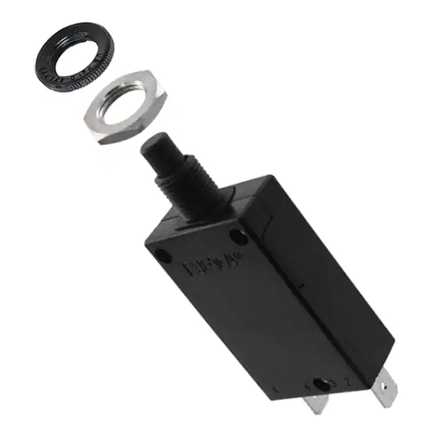
Single pole thermal circuit breaker with press-to-reset, tease-free,
trip-free, snap action mechanism. Type 2-5000 is available with optional
manual release (-H), type 2-5700 can be supplied as a push-push
switch/circuit breaker (R-type TO CBE to EN 60934 in press-to-reset
configuration; M-type when fitted with manual release -H; S-type
with push-push operation). Fitted with flange or threadneck for panel
mounting. Options include an additional unprotected circuit tap (-A3).
Approved to CBE standard EN 60934 (IEC 60934).
Typical applications
1
Motors, transformers, solenoids, battery chargers, power supplies,
appliances, machinery, extra low voltage systems.
Ordering information
2-5000-...
2-5700-...
Technical data
Type No.
2-5000 flange mounting
2-5700 threadneck panel mounting
Threadneck design – type 2-5700 only
iG1 �moulded threadneck 3/8“-27UNS-2A with metal hexnut and
plastic knurled nut (hardware bulk shipped with 5 pcs plus)
iG2 �moulded threadneck M12x1 with metal hexnut and plastic
knurled nut (hardware bulk shipped with 5 pcs plus)
Terminal design
P10 blade terminals 6.3-0.8 mm (QC .250)
K10 screw terminals M4x6
Manual release (optional)
H manual release facility (type 2-5000 only)
DD push to release/push to reset (type 2-5700 only)
Current ratings
0.05...25 A
2-5700 - iG1 - P10 - DD - 8 A
ordering example
Please be informed that we have minimum ordering quantities to be observed.
Preferred types
For further details please see: www.e-t-a.de/ti_e
Voltage rating
AC 250 V; DC 28 V
(UL: AC 250 V; DC 50 V)
Current rating range
0.05...25 A
Typical life
AC 250 V / DC 28 V:
0.05...16 A 5,000 operations at 2 x IN, inductive
17...25 A 5,000 operations at 2 x IN, resistive
Ambient temperature
-20...+60 °C (-4...+140 °F)
Insulation co-ordination
rated impulse
pollution
(IEC 60664 and 60664 A) withstand voltage degree
2.5 kV
2
reinforced insulation in operating area
Dielectric strength
(IEC 60664 and 60664A) test voltage
operating area
AC 3,000 V
Insulation resistance
> 100 MΩ (DC 500 V)
Interrupting capacity Icn 0.05...2.5 A 8 x IN
3...5 A
20 x IN
6...12 A
200 A
(higher interrupting capacity
Preferred types
Standard current ratings (A)
1
2
3
4
5
6
8 10 12 15 16 20 25
x
x
x
x
x
x
x
x
x
x
x
x
x
2-5700-IG1-P10-DD
x
x
x
x
x
x
x
x
x
x
x
2-5700-IG2-P10-
x
x
x
x
x
x
x
x
x
x
x
2-5700-IG2-P10-DD
x
x
x
x
x
x
x
x
x
x
x
2-5700-IG1-P10-
Approvals
Authority
Standard
Rated voltage
Current ratings
VDE
IEC/EN 60934
AC 250 V
DC 28 V
0.05 A…25 A
0.05 A…25 A
UL
UL 1077
AC 250 V
DC 50 V
0.05 A…20 A
0.05 A…25 A
CSA
C22.2 No 235
AC 250 V
DC 50 V
0.05 A…20 A
0.05 A…25 A
CQC
GB 17701
AC 250 V
DC 28 V
0.05 A…25 A
0.05 A…25 A
1816
available to special order)
13...25 A 300 A
Interrupting capacity
IN
UN
(UL 1077)
0.05...20 A
AC 250 V 2,000 A
0.05...25 A DC 50 V
2,500 A
(higher values upon request)
Degree of protection
operating area IP40
(IEC 60529/DIN 40050) terminal area IP00
Vibration
8 g (57-500 Hz) ± 0.61 mm (10-57 Hz),
to IEC 60068-2-6, test Fc,
10 frequency cycles/axis
Shock
25 g (11 ms)
to IEC 60068-2-27, test Ea
Corrosion
96 hours at 5 % salt mist,
to IEC 60068-2-11, test Ka
Humidity
240 hours at 95 % RH
to IEC 60068-2-78, test Cab
Mass
approx. 29 g
www.e-t-a.de
1
�Thermal Overcurrent Circuit Breakers 2-5000/2-5700-...
Dimensions
Installation drawings
2-5000-P10
2-5000-P10
operating area
7
.276
max. 2.5
max .098
18.2
.717
OFF
ø13.5
.531
44
1.73
.197
1
1
4
3
1
4
3 2
mounting area
2
19.8
.780
31
1.22
current rating in A
A
10.4
.409
A
14.5
.571
2-5700-P10
blade terminal DIN 46244-A6.3-0.8
(QC .250)
18.5
ø4.5
.177
.728
operating area
5
2-5700-P10
1
3/8
4
1
.039
ø6.5
.256
10
.394
.650
22.5
3 2
1
.039
mounting area
Standard current ratings and typical internal resistance values
A
46.5
1.83
ON
OFF
.886
16.5
iG1=3/8-27UNS-2A tightening torque max. 1 Nm
iG2=M12x1 tightening torque max. 1.5 Nm
4
3 2
10.4
.409
1
19.8
.780
29
1.14
D-shaped threadneck
blade terminal
DIN 46244-A6.3-0.8
(QC .250)
14.5
.571
current rating in A for standard
(-DD version without push button marking)
mounting hole
iG1=ø9.6-0.1
iG2=ø12.2-0.1
iG1=.378-.004
iG2=.480-.004
Terminal design
-K10
3
Current
rating (A)
Internal
resistance (Ω)
Current
rating (A)
Internal
resistance (Ω)
0.05
280
3
0.1
0.08
100
3.5
0.06
0.1
110
4
0.06
0.2
29
4.5
0.05
0.3
14
5
0.05
0.4
7
6
0.02
0.5
4.9
7
0.02
0.6
3.4
8
0.02
0.7
2.5
10
< 0.02
0.8
1.8
12
< 0.02
1
1.2
13
< 0.02
1.2
0.8
15
< 0.02
1.5
0.6
16
< 0.02
1.8
0.4
20
< 0.02
2
0.3
22
< 0.02
2.5
0.2
25
< 0.02
2
10.4
.409
4
iG1=8.9-0.1
iG2=11.5-0.1
SW 14
.551
iG1=.350-.004
iG2=.453-.004
iG1=8.8
iG2=11.3
iG1=.346
iG2=.445
5
1
25
.984
A
25
.984
40
1.57
50
1.97
max. 2.5
max .098
5
12.2
.480
ON
ø9.5
.374
flat head screw M4x6 ISO1580
tightening torque 1.2 Nm
2
This is a metric design and millimeter dimensions take precedence ( mm )
inch
www.e-t-a.de
1816
�Thermal Overcurrent Circuit Breakers 2-5000/2-5700-...
Typical time/current characteristics at +23 °C/+73.4 °F
Internal connection diagrams
1
10000
0.05 - 2.7 A
2.8 - 23 A
25 A
Trip time in seconds
1000
2
100
1
10
1
0.1
1
2
4
6 8 10
... times rated current
20
40
The time/current characteristic curve depends on the ambient temperature
prevailing. In order to eliminate nuisance tripping, please multiply the
circuit breaker current ratings by the derating factor shown below. See also
section Technical information.
Ambient temperature °F
°C
-4
-20
+14
-10
+32
0
+73.4
+23
+104
+40
+122
+50
+140
+60
Derating factor
0.76
0.84
0.92
1
1.08
1.16
1.24
This is a metric design and millimeter dimensions take precedence ( mm )
inch
1816
www.e-t-a.de
3
�Thermal Overcurrent Circuit Breakers 2-5000/2-5700-...
Accessories for types 2-5000 and 2-5700 with screw terminals -K10
176
6.93
Bus bar
Y 303 563 01
162
6.38
18
.709
X
60°
2
.079
X
1
1.1
.043
M4
10
.394
7
.276
Accessories for type 2-5000-...
Accessories for type 2-5700-...
Water splash cover, transparent
for push button (IP64)
Y 300 728 01
With 3/8" threadneck (-iG1)
Fixing plate
Y 301 056 02
19.2
.756
1.5
.059
2.3
.091
0.5
.020
Water splash cover, transparent Y 300 538 01 and
knurled nut Y 300 628 01
X 200 799 01 (IP64)
31.5
1.24
3/8-27 UNS-2B
18.5
.728
4.5
.177
50
1.97
40
1.57
14.5
.571
18
.709
Water splash cover,
transparent with
special knurled nut
X 200 798 02 (IP64)
40
1.57
50
1.97
Hex nut with splash
cover black without O ring
X 210 739 01 (IP64)
transparent splash cover
X 201 296 03 (IP64)
Rear terminal shroud, transparent (IP64)
Y 300 476 01
12.5
.492
29
1.14
3/8-27 UNS-2B
3/8-27 UNS-2B
49
1.93
E-T-A
Separate hardware
Hex nut
Y 300 192 01
Knurled nut 3/8", plastic
Y 307 117 02
3/8-27 UNS-2B
ø12
.472
3/8-27 UNS-2B
ø6
.236
SW14
.551
2.5
.098
ø15
.591
3
.118
With M12 threadneck (-iG2)
Hex nut with splash cover, black
X 200 801 03 with O ring
(IP66 and IP67)
Hex nut with splash cover,
transparent
X 200 801 08 with O ring
(IP66 and IP67)
Water splash cover,
transparent with knurled nut
and O ring
X 210 663 01 (IP64)
M12x1
M12x1
Hex nut
Y 300 116 02
Knurled nut
Y 302 065 01
M12x1
M12x1
3.2
.126
This is a metric design and millimeter dimensions take precedence ( mm )
inch
All dimensions without tolerances are for reference only. In the interest of improved design,
performance and cost effectiveness the right to make changes in these specifications
without notice is reserved.Product markings may not be exactly as the ordering codes.
Errors and omissions excepted.
4
www.e-t-a.de
SW14
.551
2.5
.098
ø17
.669
0.5 x 45°
.020 x 45°
1816
�
很抱歉,暂时无法提供与“2-5700-IG1-P10-8A”相匹配的价格&库存,您可以联系我们找货
免费人工找货