ROTARY SELECTOR SWITCHES (SMD)
CS-4
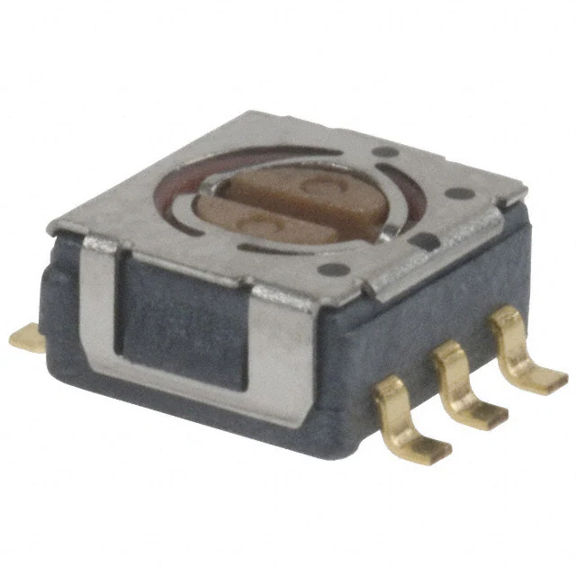
INTERNAL STRUCTURE
RoHS compliant
①
③
②
④
⑤
⑥
⑦
Part name
■ FEATURES
● RoHS compliant
● Optimum for high density board mounting applications
● Compatible with most automatic pick & place machinery
(J-hook and Gull wing types only)
● Compatible with reflow and wave soldering
● Protection against dust and washable after soldering
● Excellent reliability due to precious metal contact
● Resin materials are UL Recognized 94V-0 or 94V-1 equivalent
Material
①
Rotor
Polyphenylenesulphide
②
Cover
Stainless steel (SUS 304)
③
“O” ring
④
Fixed contact
⑤
Terminal pin
⑥
Housing
⑦
Slider contact
Silicone rubber
Copper alloy, Gold-plated
Epoxy
※ LCP(LC polymer)
Multi metal alloy
※:1 pole 4 contacts only
■ PART NUMBER DESIGNATION
CS-4 - 1 3 N T A
Series name
Shape of terminal
A:J-hook
B:Gull wing
C:Through hole pins
No. of poles
Form of packaging
1:1 pole
2:2 poles
No. of contacts
2:2 contacts
3:3 contacts
4:4 contacts
T:Taping (Reel)
Blank:Bulk in plastic bag
Contact timing
N:Non-shorting (1 pole 3, 4 contacts only)
Y:Non-shorting with neutral detent
(1pole 2 contacts, 2 poles 2 contacts)
X:Non-shorting without neutral detent (1 pole 2 contacts only)
※ Please refer to the LIST OF PART NUMBERS when placing orders.
�CS-4
ROTARY SELECTOR SWITCHES (SMD)
CS-4
回路図
1p
2c
CS-4
回路図
1p
2c
CS-4
回路図
1p
2c
CS-4
回路図
1p
2c
CS-4■回路図
1p
2c DIAGRAMS
SCHEMATICS
CS-4
回路図
1p
CS-4 回路図 1p 2c
2c
● 1 pole 2 contacts
C
CC
C
CS-4-12YA
11
11
1
〃 YTA
1
1
C
C
22
2
2
OFF
OFF
OFF
OFF
OFF
OFF
OFF
ON
ON
C
C
CC
C
CS-4-12XA
C
C
1
11
1
1
〃 XB
〃 XTB
CC
CC
C
C
C
2
22
2
2
2
2
1
1
〃 XC
C
CC
C
C ON
ON
ON
C ON
C ON
ON
ON
1
11
1
1
1
1
ON
ON
1
NC C
1
C
C
C ON 1
4
3
2
4
3
2
NC4 C3 12
CS-4-14NA
〃 NTA
3
2
〃 NB
12
CC
ON
ON
C ON 2
ON
CC
23
C
〃 NTB
2
22
1
1
2
2
C
C
3
ON
ON
C ON 3
3
3
Schematic
11
CC
1
C ON
ON
1
C
ON
ON
CC
C
C
C
2
C
2
C ON 2
C ON 2
ON
ON
C
C
C ON
C ON
1 2 3
1
1 223 3
1 2 3
3
3
3
3
$4���ճ࿏ਤ��Q��D
$4���ճ࿏ਤ��Q��D
ON
$4���ճ࿏ਤ��Q��D
ON
● 2 poles 2 contacts
Series
Switching specifications
1
11
2
22
2
2
2
2
C
C
CC
2
2
22
C
CC
C
C
CC
C
CS-4-22YA
Schematic
C
C
33
〃 NTB
22
22
〃 YTB
1
1
2
12
3
23
4
34 1
Schematic
1
111
ON
ON
1
11
1
ON
CC 11
CC 11
C
CC
C
OFF
OFF
OFF
〃 YB
1
1
ON
C
4
ON
11
〃 NB
〃 YTA
C
NC
CC
Switching
specifications
1
NC C 1 specifications
Switching
Series
〃 NTA
C
CC
CC
C
C
1
11
11
1
1
2
C
22
CC
C ON 2
C ON
ON 22
C ON
C ON 2
● 1 pole 4 contacts
CS-4-13NA
22
2
22
2
2
11
1
11
1
1
CC
22
C
2
C ON
ON 22
C ON
ON 22
C ON
〃 YC
Series
C
C
ON
ON
2
2
〃 YTB
Schematic
CC ON 11
C ON 1
ON
ON
C ON 1
C
1
〃 YB
〃 XTA
● 1 pole 3 contacts
C
Switching specifications
CC
11
Series
CS-4
1p 3c
3c
CS-4 回路図 1p
CS-4
回路図
1p
3c
CS-4 回路図 1p 3c
22
22
11
11
CC
C
2222
CC
C
22
2
ON
ON
ON
1
11
1
CC
CC
22
22
42
3
4
ON
C
CC
4
34
ON
C ON
ON 4
ON
■ LIST OF PART NUMBERS
C
Circuit type
1
2
1
1
2
4
ON of packaging
Form
Taping
Plastic bag
pole
contacts
Taping
Without neutral detent
Plastic bag
Taping
pole 3 contacts
Plastic bag
Taping
pole 4 contacts
Plastic bag
Taping
poles 2 contacts
Plastic bag
With neutral detent
: Not manufactured
※ Verify the above part numbers when placing orders.
Taping version can be supplied only in reel unit.
A
J-hook
CS-4-12YTA
CS-4-12YA
CS-4-12XTA
CS-4-12XA
CS-4-13NTA
CS-4-13NA
CS-4-14NTA
CS-4-14NA
CS-4-22YTA
CS-4-22YA
B
Gull wing
CS-4-12YTB
CS-4-12YB
CS-4-12XTB
CS-4-12XB
CS-4-13NTB
CS-4-13NB
CS-4-14NTB
CS-4-14NB
CS-4-22YTB
CS-4-22YB
C
Through hole pin
CS-4-12YC
CS-4-12XC
Pieces in package
500 pcs. /reel
50 pcs./pack
500 pcs./reel
50 pcs./pack
500 pcs./reel
50 pcs./pack
500 pcs./reel
50 pcs./pack
500 pcs./reel
50 pcs./pack
�CS-4
ROTARY SELECTOR SWITCHES (SMD)
■ STANDARD SPECIFICATIONS
Circuit type
1 pole 2 contacts 2 poles 2 contacts
1 pole 3 contacts
1 pole 4 contacts
■ ELECTRICAL CHARACTERISTICS
0.5 VA
Contact rating
Maximum current
100 mA
Operating temperature range
− 25 ~ 70 °C
Minimum current
1μA
Storage temperature range
− 40 ~ 70 °C
Maximum voltage
16 V
Minimum voltage
20 mV
Sealing
Washable by “O” ring
※ Please refer to page 150, 151
Net weight
Approx. 0.08 g (CS-4-12, CS-4-13)
Approx. 0.1 g (CS-4-14, CS-4-22)
Non-shorting
Contact timing
100 mΩ maximum
Contact resistance
100 MΩ (DC500 V) minimum
Insulation resistance
■ MECHANICAL CHARACTERISTICS
No. of positions
2, 3, 4
Adjustment torque
10 mN·m {102 gf·cm} maximum
Stopper strength
25 mN·m {255 gf·cm} minimum
Stepping angle
Solderability
45°
90° (CS-4-12X only)
245 ± 3 °C, 2 ~ 3 s
AC500 V, 60 s
Dielectric strength
■ ENVIRONMENTAL CHARACTERISTICS
(Amplitude) 1.5 mm(or
(Acceleration) 98 m/s2,
10-500-10 Hz,
3 directions for 2 h each
490 m/s2, 11 ms
6 directions for 3 times each
200 cycles minimum
DC16 V, 30 mA
Vibration
Shock
Load life
Soldering heat
Flow : 260 ± 3 °C as the temperature in a
pot of molten solder, immersion
from head of terminal to backside of
board,
5 ~ 6 s, two times maximum
Reflow : Peak temperature 255 °C
(Please refer to the profile below.)
Manual soldering:350 ± 10 °C, 3 ~ 4 s
40 °C, Relative humidity 90 ~ 95 %, 48 h
Humidity (Steady state)
High temperature exposure
70 °C, 16 h
Low temperature exposure
− 40 °C, 16 h
Thermal shock
− 40 (0.5 h) ~ 70 °C (0.5 h), 5 cycles
〈Reflow profile for soldering heat evaluation〉
5 N {0.51 kgf}, 10 s
Substrate bending
Width 90 mm, bend 3 mm, 5 s, 1 time
Pull-off strength
5 N {0.51 kgf}, 10 s
{ } : Reference only
(C)
250
Peak : 250
200
Pre Heating Zone
+5
0
C
Over 230 C
Temperature
Shear (Adhesion)
150
100
50
180 C
150 C
90 30 s
30 10 s
Heating time
Soldering Zone
Reflow : two times maximum
�CS-4
ROTARY SELECTOR SWITCHES (SMD)
2YA
CS-4-12YB
■ OUTLINE DIMENSIONS
Unless otherwise specified, tolerance: ± 0.3 (Unit: mm)
● CS-4-12YA
● CS-4-12YB
0.6 × ¥ 2.3 L × 0.5 D
1.2
Production date code
Production date code
3
CS-4-12XA
2 – 0.8
t = 0.15
2
5
2.3
6.2
1
2.35
2
5
● CS-4-12YC
0.6 W × 2.3 L × 0.5 D
3 – 0.6
t = 0.15
1
2.54
41
0.35 min.
5.08
6.2
2.3
2 – 0.8
t = 0.15
1
2
2.3
5
2.35
● CS-4-13NA
41
2.54
● CS-4-13NB
0.6 × ¥ 2.3 L × 0.5 D
2.3
1.3
● CS-4-14NA
1.2
6.2
2.3
4.5
3
0
– 0.5
4.5
5.2
3 – 0.5
t = 0.15
1.3
2 3
5
Production date code
0.35 min.
C
C
0.35 min.
0.6 W × 2.3 L × 0.5 D
1.2
Production date code
1 2 3
5
1.3
3 – 0.5
t = 0.15
1.3
● CS-4-14NB
0.6 W × 2.3 L × 0.5 D
3 – 45°
Step angle
Production date code
4.5
3
5.2
4.5
0
– 0.5
Production date code
3 – 45°
Step angle
4 3 2
135°
Moving range
2.3
1.3
1.3
6 – 0.5
t = 0.15
6.2
NC C 1
0.35 min.
0.6 W × 2.3 L × 0.5 D
6 – 0.5
t = 0.15
4 3 2
5
3 – 0.6
t = 0.15
Production date code
C
0.35 min.
5
NC C 1
2.35
0.6 W × 2.3 L × 0.5 D
1.2
CS-4-13NB 外形図
2
1
2.3
4.5
Production date code
4.5
1
2 – 0.8
t = 0.15
2
5
● CS-4-12XC
0.6 W × 2.3 L × 0.5 D
C
3
5.08
4.5
2.3
5
● CS-4-12XB
形図
4.5
CS-4-12XC
2
1.2
Production date code
C
5.2 – 00.5
Production date code
C
1
2 – 0.8
t = 0.15
2.35
● CS-4-12XA
0.6 W ×2.3 L × 0.5 D
S-4-12XB
2.3
5
135°
Moving range
2.3
0.35 min.
1
4.5
5.2
4.5
0
– 0.5
C
1.2
0.35 min.
C
-12YC
0.35 min.
0.6 W × 2.3 L × 0.5 D
1.3
1.3
�CS-4
ROTARY SELECTOR SWITCHES (SMD)
CS-4-22YB 外形図
■ OUTLINE DIMENSIONS
Unless otherwise specified, tolerance: ± 0.3 (Unit: mm)
0.6 W × 2.3 L × 0.5 D
0.6 W × 2.3 L × 0.5 D
1
1 C
2
2.3
3
4.5
5
1.3
1.3
製造年月記号
Production date code
2
C 1
5
2.3
■ RECOMMENDED P.C.B. PAD OUTLINE DIMENSIONS
2
● CS-4-12YB
● CS-4-12XB
4
2
0
2
2
0
1.6
1.6
2.35
1.3
1.5
0.6
1.3
0
1.3
1.5
5
0.6
1.5
1.3
1.3
● CS-4-14NB
● CS-4-22YB
3
0.6
1.5
0
0
1.5
1.3
● CS-4-14NA
● CS-4-22YA
2
● CS-4-13NB
1.5
1.5
0.6
1.5
0
2.35
3
2
● CS-4-13NA
1.6
5
1.6
1.3
(Unit: mm)
2
2
1.3
2
● CS-4-12YA
● CS-4-12XA
6 – 0.5
t = 0.15
6.2
2 C
݄߸ه
Production date code
4.5
2
5.2– 00.5
1 C
6 – 0.5
t = 0.15
0.35 min.
● CS-4-22YB
● CS-4-22YA
0.35 min.
֎ܗਤ
1.3
1.3
Note) The zero point is the center of mounting.
�CS-4
ROTARY SELECTOR SWITCHES (SMD)
$4���Μͩ݅
■ SOLDERING CONDITIONS
When dip-soldering CS-4-13NA, NB or CS-4-22YA, YB, solder bridges may occur between terminals depending upon soldering
conditions.
In order to prevent such bridges,vertical flow direction is recommended as shown in the below figure.
For dip-soldering,preheating should be done after apply-ing flux.
Handle carefully in case of parallel flow direction in which solder bridges occur more often because solder flow moves toward
the vertical direction against the terminals.
In addition, other soldering conditions such as soldering temperature, preheating temperature, specific gravity of flux, and belt
speed affect the occurrence of bridges.
Depending on flux to be applied, markings may, though at rare case, disappear or fade out at soldering. Please make sure
before its use.
Flow direction
CS-4-13NA, NB
CS-4-22YA, YB
P.C.B.
P.C.B.
Vertical
Solder
bath
Parallel
Solder
bath
�CS-4
ROTARY SELECTOR SWITCHES (SMD)
$4���Ϧʔϧ
■ PACKAGING SPECIFICATIONS
● Taping version is packaged in 500 pcs. per reel.
Orders will be accepted for units of 500 pcs., i.e., 500, 1000, 1500 pcs., etc.
● Taping version is boxed with 4 reels (2000 pcs.).
Maximum number of consecutive missing pieces=2
Leader length and reel dimension are shown in the dia-grams below:
● Reel dimensions
● Embossed tape dimensions
(Unit: mm)
(Conforms to JIS C 0806-3)
(In accordance with EIAJ ET-7200A)
13
Filled
Empty
φ 21±0.8
End
2±0.5
φ 60 +10
Empty
Head
40 mm min.
φ 13±0.2
20 pitches min.
Leader
400 mm min.
Direction of feed Taping (J)
CS-4TA/TB
0
φ 180 –1.5
● CS-4- □□□ TA/CS-4- □□□ TB
15.4±1
(Conforms to JIS C 0806)
(Unit: mm)
80.1
40.1
20.05
1.750.1
φ 1.5+0.1
0
+1
0
0.30.1
(CS-4A)
12
5.50.05
Installation example
2.7
Direction of feed
● The smallest unit of bulk pack in a plastic bag is 10 pcs. per pack. Orders will be accepted for unit of minimum 10 pcs., i.e.,
10, 20, 30 pcs. , etc.
● Boxing of bulk in a plastic bag is performed with 50 pcs. (standard 500 pcs.) per box.
�