FH43BW-35S-0.2SHW(10) 数据手册
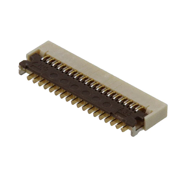
0.2 mm Pitch, 0.9 mm Height FPC Connectors
FH43B Series
m
7m
2.7
11.8
mm(
0.9mm
The staggered lead structure simplifies PCB mounting and provides
a low profile height of 0.9 mm and a 2.77 mm mounting width depth.
51 p
os.)
Aug.1.2019 Copyright 2019 HIROSE ELECTRIC CO., LTD. All Rights Reserved.
Fig 1.
■Features
FH43B differential impedance
1. 0.2 mm pitch low profile bottom contact
FPC connector
Spec MAX : 115ohm
Maximizes space with contact pitch of 0.2 mm, a mated
height of 0.9 mm, and mounted depth of 2.77 mm.
*45% reduction in occupied PCB area
*55% reduction in weight
(Compared to our 0.3 mm pitch FH26 Series 51 position connector)
97.2
2. Easy PCB mounting
100.6
Connector
The PCB leads use 0.4 mm pitch and are staggered
which simplifies the PCB mounting process.
FPC
Spec MIN : 85ohm
3. Supports high-speed transmissions
By utilizing differential pairs of identical contacts
(even - even contact or odd - odd contacts) these
connectors are able to provide superb transmission
characteristics and supports eDP (ver. 1.3), MIPI
(D-PHY), HDMI (ver 1.3), and USB (3.0) standards.
impedance@200ps rise time(10-90%)
FPC insertion
Actuator open
4. Molded structure aids PCB layout
The bottom of this connector is enclosed by a fully
molded structure that protects the contacts and removes
any restrictions from PCB patterning and layout design.
5. Rotating one-touch ZIF mechanism
The one-touch rotating ZIF mechanism is easier to
operate and works with a light force, and a clear tactile
click is delivered upon the successful completion of the
mating process.
FPC
6. Easy FPC insertion
The FPC aligning mechanism holds onto the FPC
prior to locking the actuator.
With actuator locked
7. Insertion check window
There is a cutout on the actuator that allows you to
visually inspect the FPC to make sure that it is locked
into place, preventing incorrect insertion of the FPC.
8. Accepts standard 0.2 mm thick FPC
This connector accepts standard 0.2 mm thick FPC.
(A stiffener with adequate strength will prevent FPC
deformation and ease insertion and mating.)
9. Halogen-free available (FH43BW Series)
The connector does not use chlorine and bromine
exceeding standard limits. (FH43BW Series)
*Defined in accordance with IEC61249-2-21
Br 900ppm or lower, Cl 900ppm or lower, Br + Cl
1,500ppm or lower
FPC temporary
retention system
10.Available for 500 pieces packaging
Although the normal product is 5,000 pieces per reel,
500 winds per reel is also available.
(Emboss reel external diameter is Ø180mm.)
FPC temporary
retention system
In cases where the application will demand a high level of reliability, such as automotive,
please contact a company representative for further information.
visual check area
to confirm mating
2014.3w
1
�FH43B Series●0.2 mm Pitch, 0.9 mm Height FPC Connectors
■Product Specifications
Current DC 0.2 A
Rating (Note 1)
Rating
Voltage
Operating
AC 30 Vrms
Rating
Humidity Range
Recommended FPC spec
Items
Storage Temperature
Range
Relative humidity 90% max Storing Humidity
(should be no condensation) Range
Specifications
100 V DC
2. Withstanding Voltage
No flashover or breakdown
100 mø Max.
*Excluding FPC conductor resistance
90 V AC for 1 Min
1 mA
Contact Resistance: 100 mø Max
No damage, cracks and looseness of parts
5. Vibration
6. Shock
7. Humidity
(Steady State)
8. Temperature Cycle
9. Resistance to
soldering heat
Relative humidity 90% max
(should be no condensation)
Conditions
50 Mø Min
4. Durability
-10 to +50℃ (Note 3)
t = 0.2 ±0.02 Gold plating
1. Insulation Resistance
3. Contact Resistance
Aug.1.2019 Copyright 2019 HIROSE ELECTRIC CO., LTD. All Rights Reserved.
Operating
-55 to +85℃ (Note 2)
Temperature Range
No electrical discontinuity of 1µ or longer
Contact Resistance: 100 mø Max
No damage, cracks and looseness of parts
No electric discontinuity of 1µ or longer
Contact Resistance: 100 mø Max
No damage, cracks and looseness of parts
Contact Resistance: 100 mø Max
Insulation Resistance: 50 Mø Min
No damage, cracks and looseness of parts
Contact Resistance: 100 mø Max
Insulation Resistance: 50 Mø Min
No damage, cracks and looseness of parts
No deformation of case of excessive
looseness of the terminal
10 cycles
Frequency 10 to 55Hz, Half amplitude 0.75 mm
for 10 cycles in 3 axial directions
2
Acceleration: 981 m/s , Retention time: 6 ms, Semisinusoidal 3 times in 3 both axial directions
96 hours at 40ç and humidity of 90 to 95%
Temperature: -55 → +15 to +35 → +85 → +15 to +35ç
Time:
30 →
2 to 3
→ 30 → 2 to 3 minutes
5 cycles
1) Reflow: Peak TMP 250ç MAX, reflow TMP over 230ç within 60 seconds
2) Manual soldering: 350 ±10ç for 5 seconds
(Note 1) When electrifying rated current to all contacts, use 70% of rated current.
(Note 2) Includes temperature rise caused by current flow.
(Note 3) The term “storage” refers to the long-term storage condition of unused products before PCB mounting.
For no-electrification state after PCB mounting, the operating temperature and humidity are applied.
■Materials
Product
Materials
Color/Finish
LCP
Beige
Insulator
FH43B Series: Deep brown
PA
Contacts
Phosphor bronze
Metal fittings
Remarks
UL94V-0
FH43BW Series: Black
UL94HB
Gold plating
―
Pure tin reflow plating
―
■Product Number Structure
Refer to this page when determining product specifications by model types. Please place orders with part numbers listed in this catalog. The characteristics and
specifications of the product described in this catalog are reference values. Please make sure to check the latest delivery specifications at the time of product use.
FH 43B W − 51S − 0.2 SHW (10)
❶
❷
❸
❶ Series Name: FH
❷ Series No.: 43B
❸ Blank: Standard
W: Halogen-free product
❹ No. of Contacts: 21~71
❺ Contact Pitch: 0.2 mm
2
❹
❺
❻
❼
❻ Terminal Type
SHW ... SMT horizontal staggered row mounting type
❼ Specifications
(10):Nickel barrier gold plating, 5,000
pieces per reel
(99):Nickel barrier gold plating 500
pieces per reel
�FH43B Series●0.2 mm Pitch, 0.9 mm Height FPC Connectors
■Connector Dimensions
(0.08)
P Enlarged figure
Lot No.
HRS mark
Polarization mark
0.4±0.1
Cavity No.
No. of contacts
(0.08)
C±0.1
Aug.1.2019 Copyright 2019 HIROSE ELECTRIC CO., LTD. All Rights Reserved.
P
(D)
E±0.1
Contact point
(0.31)
Contact No.1
FPC:t0.2
(0.95)
(2.85)
(2.08)
0.9±0.1
(1.75)
(2)
0.4±0.1
Contact No.2
A±0.15
B±0.1
(9
(1 0°)
25
°)
0.2±0.1
(0.53)
(1.2)
(1.6)
2.17±0.15
0.47±0.1
0.4±0.15
(0.12)
0.3±0.1
0.2±0.15
(0.45)
(2.5)
Note 1: The dimensions in parentheses are for reference.
2: Lead coplanarity including reinforced metal fittings shall be 0.1 mm MAX.
3: To be delivered with tape and reel packages. See attached packaging specifications for details.
4: Note that preventive hole for sink mark or slit could be added for improvement.
5: The quality remains good, even with the dark spots, which could occasionally occur on molded plastic.
6: The color of the plating may change after the reflow process, but it will not negatively affect the performance of these
connectors.
Unit: mm
HRS No.
No. of Contacts
A
B
C
D
E
FH43B-21S-0.2SHW(**)
Product No.
CL580-2810-0-**
21
5.8
3.6
4
4.53
5.29
FH43B-25S-0.2SHW(**)
CL580-2804-8-**
25
6.6
4.4
4.8
5.33
6.09
FH43B-29S-0.2SHW(**)
CL580-2811-3-**
29
7.4
5.2
5.6
6.13
6.89
FH43B-31S-0.2SHW(**)
CL580-2808-9-**
31
7.8
5.6
6
6.53
7.29
FH43B-35S-0.2SHW(**)
CL580-2803-5-**
35
8.6
6.4
6.8
7.33
8.09
FH43B-41S-0.2SHW(**)
CL580-2809-1-**
41
9.8
7.6
8
8.53
9.29
FH43B-45S-0.2SHW(**)
CL580-2812-6-**
45
10.6
8.4
8.8
9.33
10.09
FH43B-51S-0.2SHW(**)
CL580-2806-3-**
51
11.8
9.6
10
10.53
11.29
FH43B-61S-0.2SHW(**)
CL580-2805-0-**
61
13.8
11.6
12
12.53
13.29
FH43B-71S-0.2SHW(**)
CL580-2807-6-**
71
15.8
13.6
14
14.53
15.29
Product No.
HRS No.
No. of Contacts
A
B
C
D
E
FH43BW-21S-0.2SHW(**)
CL580-2822-0-**
21
5.8
3.6
4
4.53
5.29
FH43BW-25S-0.2SHW(**)
-
25
6.6
4.4
4.8
5.33
6.09
FH43BW-29S-0.2SHW(**)
-
29
7.4
5.2
5.6
6.13
6.89
FH43BW-31S-0.2SHW(**)
CL580-2820-4-**
31
7.8
5.6
6
6.53
7.29
FH43BW-35S-0.2SHW(**)
CL580-2821-7-**
35
8.6
6.4
6.8
7.33
8.09
FH43BW-41S-0.2SHW(**)
CL580-2813-9-**
41
9.8
7.6
8
8.53
9.29
FH43BW-45S-0.2SHW(**)
CL580-2815-4-**
45
10.6
8.4
8.8
9.33
10.09
FH43BW-51S-0.2SHW(**)
CL580-2814-1-**
51
11.8
9.6
10
10.53
11.29
FH43BW-61S-0.2SHW(**)
CL580-2816-7-**
61
13.8
11.6
12
12.53
13.29
FH43BW-71S-0.2SHW(**)
CL580-2819-5-**
71
15.8
13.6
14
14.53
15.29
(Note 1)This product is packaged on tape and reel and is only sold in full reel quantities of either 5,000 or 500 piece reels.
Please place orders by full reel quantities.
3
�FH43B Series●0.2 mm Pitch, 0.9 mm Height FPC Connectors
BRecommended PCB Mounting Pattern
B
0.4
(0.2)
0.65±0.03
0.2
0.2±0.02
Contact No.2
(n-1)/2×
0.04
Contact No.1
0.4±0.05
0.4
X
Aug.1.2019 Copyright 2019 HIROSE ELECTRIC CO., LTD. All Rights Reserved.
0.2±0.02
C±0.04
(n+1)/2×
0.04
0.485±0.05
0.9±0.03
1.6±0.05
1.65±0.05
0.87±0.03
3.17±0.05
Connector Image (Mounting Section)
0.55±0.03
BRecommended Stencil Pattern
(Recommended stencil thickness: t= 0.1)
0.2
B
0.4
0.18±0.01
(n-1)/2×
0.04 Y
1.92±0.05
0.3±0.03
0.4
0.18±0.01
C±0.04
Y
(n+1)/2×
0.04 Y
0.585±0.05
0.68±0.03
1.94±0.05
0.68±0.03
3.17±0.05
(PCB mounting pattern image)
Note 7: 'n' is the number of contacts.
Product No.
4
Unit: mm
C
HRS No.
No. of Contacts
B
FH43B-21S-0.2SHW(**)
CL580-2810-0-**
21
3.6
4
FH43B-25S-0.2SHW(**)
CL580-2804-8-**
25
4.4
4.8
FH43B-29S-0.2SHW(**)
CL580-2811-3-**
29
5.2
5.6
FH43B-31S-0.2SHW(**)
CL580-2808-9-**
31
5.6
6
FH43B-35S-0.2SHW(**)
CL580-2803-5-**
35
6.4
6.8
FH43B-41S-0.2SHW(**)
CL580-2809-1-**
41
7.6
8
FH43B-45S-0.2SHW(**)
CL580-2812-6-**
45
8.4
8.8
FH43B-51S-0.2SHW(**)
CL580-2806-3-**
51
9.6
10
FH43B-61S-0.2SHW(**)
CL580-2805-0-**
61
11.6
12
FH43B-71S-0.2SHW(**)
CL580-2807-6-**
71
13.6
14
Product No.
HRS No.
No. of Contacts
B
C
FH43BW-21S-0.2SHW(**)
CL580-2822-0-**
21
3.6
4
FH43BW-25S-0.2SHW(**)
-
25
4.4
4.8
FH43BW-29S-0.2SHW(**)
-
29
5.2
5.6
FH43BW-31S-0.2SHW(**)
CL580-2820-4-**
31
5.6
6
FH43BW-35S-0.2SHW(**)
CL580-2821-7-**
35
6.4
6.8
FH43BW-41S-0.2SHW(**)
CL580-2813-9-**
41
7.6
8
FH43BW-45S-0.2SHW(**)
CL580-2815-4-**
45
8.4
8.8
FH43BW-51S-0.2SHW(**)
CL580-2814-1-**
51
9.6
10
FH43BW-61S-0.2SHW(**)
CL580-2816-7-**
61
11.6
12
FH43BW-71S-0.2SHW(**)
CL580-2819-5-**
71
13.6
14
�FH43B Series●0.2 mm Pitch, 0.9 mm Height FPC Connectors
BRecommended FPC Pattern
0.25±0.05
0.25±0.05
C±0.02
R
0.4
0.4
(n+1)/2×
0.04 Z
R0.2MAX
Contact No.1
R0.2MAX
R0.2±0.1
R0.2±0.1
3.1±0.3(Stiffener)
2.1±0.3
1.6±0.05
1.1±0.05
Z
0.2+0.03
−0.02
8 0.1±0.03
8 0.1±0.03
8 0.055±0.02
0.2
0.75±0.1(Odd pattern)
0.76±0.1(Even pattern)
1.55±0.15
0.74±0.1(Even pattern)
0.75±0.1(Odd pattern)
1.45±0.1
0.2±0.02
A±0.1
(F)
G±0.05
R0.2MAX
9
0.055±0.02
0.2+0.03
−0.02
0.67±0.05
10
Q
0.1±0.15
(n-1)/2×
B
9 H±0.05
9
0.04 Z
0.67±0.05
R Enlarged figure
U
V
(0.05)
: Shows recommended demension when lead for plating is required.
: Indicated tolerance is applicable to the exposed conductor.
: Dimension Q must be 0.5 mm minimum.
(0.35)
Note 8
9
10
(Reference shape)
Check mark for
press misalignment
(0)
*Relative positions of point-U and V
(0.01)
*Relative positions of point-S and T
(0.10:Even pattern)
(0.13:Odd pattern)
(0.5)
Aug.1.2019 Copyright 2019 HIROSE ELECTRIC CO., LTD. All Rights Reserved.
Contact No.2
T
S
0.01±0.02
Unit: mm
Product No.
HRS No.
No. of Contacts
A
B
C
F
G
H
FH43B-21S-0.2SHW(**)
CL580-2810-0-**
21
5.8
3.6
4
5.3
4.5
4.94
FH43B-25S-0.2SHW(**)
CL580-2804-8-**
25
6.6
4.4
4.8
6.1
5.3
5.74
FH43B-29S-0.2SHW(**)
CL580-2811-3-**
29
7.4
5.2
5.6
6.9
6.1
6.54
FH43B-31S-0.2SHW(**)
CL580-2808-9-**
31
7.8
5.6
6
7.3
6.5
6.94
FH43B-35S-0.2SHW(**)
CL580-2803-5-**
35
8.6
6.4
6.8
8.1
7.3
7.74
FH43B-41S-0.2SHW(**)
CL580-2809-1-**
41
9.8
7.6
8
9.3
8.5
8.94
FH43B-45S-0.2SHW(**)
CL580-2812-6-**
45
10.6
8.4
8.8
10.1
9.3
9.74
FH43B-51S-0.2SHW(**)
CL580-2806-3-**
51
11.8
9.6
10
11.3
10.5
10.94
FH43B-61S-0.2SHW(**)
CL580-2805-0-**
61
13.8
11.6
12
13.3
12.5
12.94
FH43B-71S-0.2SHW(**)
CL580-2807-6-**
71
15.8
13.6
14
15.3
14.5
14.94
Product No.
HRS No.
No. of Contacts
A
B
C
F
G
H
FH43BW-21S-0.2SHW(**)
CL580-2822-0-**
21
5.8
3.6
4
5.3
4.5
4.94
FH43BW-25S-0.2SHW(**)
-
25
6.6
4.4
4.8
6.1
5.3
5.74
FH43BW-29S-0.2SHW(**)
-
29
7.4
5.2
5.6
6.9
6.1
6.54
FH43BW-31S-0.2SHW(**)
CL580-2820-4-**
31
7.8
5.6
6
7.3
6.5
6.94
FH43BW-35S-0.2SHW(**)
CL580-2821-7-**
35
8.6
6.4
6.8
8.1
7.3
7.74
FH43BW-41S-0.2SHW(**)
CL580-2813-9-**
41
9.8
7.6
8
9.3
8.5
8.94
FH43BW-45S-0.2SHW(**)
CL580-2815-4-**
45
10.6
8.4
8.8
10.1
9.3
9.74
FH43BW-51S-0.2SHW(**)
CL580-2814-1-**
51
11.8
9.6
10
11.3
10.5
10.94
FH43BW-61S-0.2SHW(**)
CL580-2816-7-**
61
13.8
11.6
12
13.3
12.5
12.94
FH43BW-71S-0.2SHW(**)
CL580-2819-5-**
71
15.8
13.6
14
15.3
14.5
14.94
5
�FH43B Series●0.2 mm Pitch, 0.9 mm Height FPC Connectors
BFPC Material Configuration (Reference Example)
Single-Sided FPC
Material name
Material
Covering film layer
Polyimide 1 mil
Aug.1.2019 Copyright 2019 HIROSE ELECTRIC CO., LTD. All Rights Reserved.
1 µm to 6 µm Nickel underplated +
0.2 µm Gold plated
4
12
Copper foil
Cu 1/3 oz
Base adhesive
Heat-hardened adhesive No adhesion material
Base film
Polyimide 1 mil
25
Reinforcement material adhesive
Heat-hardened adhesive
30
Stiffener
Polyimide 5 mil
125
Total
196
Precautions
1. This specification is a recommendation for the construction of the FH43B Series FPC (t=0.2±0.02).
2. For details about the construction, please contact the FPC manufacturers.
6
(25)
(25)
Cover adhesive
Surface treatment
Thickness
(µm)
�FH43B Series●0.2 mm Pitch, 0.9 mm Height FPC Connectors
BPackaging Specifications
1.75±0.1
J±0.3
L±0.1
●Reel Condition Dimensions
Ø1.7 0
+0.1
Ø1.5 0
+0.15
K±0.1
J±0.3
Direction of unreeling
●Leader, Trailer Dimensions
(M: Inside)
(Ø13)
400 mm MIN (Leader)
Direction
of unreeling
(Ø380)
(Ø80)
Aug.1.2019 Copyright 2019 HIROSE ELECTRIC CO., LTD. All Rights Reserved.
4±0.1
(2)
L±0.1
(2)
+0
0 .1
4±0.1
(0.3)
1.75±0.1
+0
0 .1
(0.3)
8±0.1
(1.2)
8±0.1
Ø1
.5
(1.2)
●Embossed Carrier Tape Dimension (Tape width: 32 mm MIN)
Ø1
.5
●Embossed Carrier Tape Dimension (Tape width: 24 mm MAX)
160 mm MIN
(Trailer, Empty)
Embossed carrier tape
100 mm MIN
(Empty)
Top cover tape
(N: Outside)
Unit: mm
Product No.
HRS No.
No. of Contacts
J
K
L
M
N
FH43B-21S-0.2SHW(**)
CL580-2810-0-**
21
16
-
7.5
17.4
21.4
FH43B-25S-0.2SHW(**)
CL580-2804-8-**
25
16
-
7.5
17.4
21.4
FH43B-29S-0.2SHW(**)
CL580-2811-3-**
29
16
-
7.5
17.4
21.4
FH43B-31S-0.2SHW(**)
CL580-2808-9-**
31
24
-
11.5
25.4
29.4
FH43B-35S-0.2SHW(**)
CL580-2803-5-**
35
24
-
11.5
25.4
29.4
FH43B-41S-0.2SHW(**)
CL580-2809-1-**
41
24
-
11.5
25.4
29.4
FH43B-45S-0.2SHW(**)
CL580-2812-6-**
45
24
-
11.5
25.4
29.4
FH43B-51S-0.2SHW(**)
CL580-2806-3-**
51
24
-
11.5
25.4
29.4
FH43B-61S-0.2SHW(**)
CL580-2805-0-**
61
24
-
11.5
25.4
29.4
FH43B-71S-0.2SHW(**)
CL580-2807-6-**
71
32
28.4
14.2
33.4
37.4
HRS No.
No. of Contacts
J
K
L
M
N
Product No.
FH43BW-21S-0.2SHW(**)
CL580-2822-0-**
21
16
-
7.5
17.4
21.4
FH43BW-25S-0.2SHW(**)
-
25
16
-
7.5
17.4
21.4
FH43BW-29S-0.2SHW(**)
-
29
16
-
7.5
17.4
21.4
FH43BW-31S-0.2SHW(**)
CL580-2820-4-**
31
24
-
11.5
25.4
29.4
FH43BW-35S-0.2SHW(**)
CL580-2821-7-**
35
24
-
11.5
25.4
29.4
FH43BW-41S-0.2SHW(**)
CL580-2813-9-**
41
24
-
11.5
25.4
29.4
FH43BW-45S-0.2SHW(**)
CL580-2815-4-**
45
24
-
11.5
25.4
29.4
FH43BW-51S-0.2SHW(**)
CL580-2814-1-**
51
24
-
11.5
25.4
29.4
FH43BW-61S-0.2SHW(**)
CL580-2816-7-**
61
24
-
11.5
25.4
29.4
FH43BW-71S-0.2SHW(**)
CL580-2819-5-**
71
32
28.4
14.2
33.4
37.4
7
�FH43B Series●0.2 mm Pitch, 0.9 mm Height FPC Connectors
BTemperature Profile
MAX 250ç
250
Temperature (ç)
230ç
200
200ç
150
150ç
Applicable Conditions
Reflow method:IR/Hot air
Reflow environment :Room air
Solder
:Paste type Sn/3.0Ag/0.5Cu
(M705-GRN360-K2-V made by Senju
Metal Industry Co.)
Test PCB
:PCB material and size
Glass epoxy 100×72.5×0.8mm
Land pattern 0.2×0.65, 0.2×0.87mm
Stencil
:Thickness 0.1mm
Opening size 0.18×0.55, 0.18×0.68mm
100
Aug.1.2019 Copyright 2019 HIROSE ELECTRIC CO., LTD. All Rights Reserved.
50
25ç
(60sec)
0
90∼120sec
Pre-heating
Start
Time (sec)
8
(60sec)
Soldering
The temperature profiles are based on the above
conditions.
In individual applications the actual temperature may
vary, depending on solder paste type, volume/thickness
and board size/thickness.
Consult your solder paste and equipment manufacturer
for specific recommendations.
�FH43B Series●0.2 mm Pitch, 0.9 mm Height FPC Connectors
BOperation and Precautions
Operation Methods
This connector needs to be handled with care due to its thin design and miniature stature. Please refer to
the following descriptions for handling precautions.
1. Initial Delivery Condition
Aug.1.2019 Copyright 2019 HIROSE ELECTRIC CO., LTD. All Rights Reserved.
❶ The connector is delivered with the actuator closed.
[Caution]
・Do not insert FPC or operate actuator before mounting.
2. How to unlock
❶ Rotate slowly flip up the actuator to release the lock.
[Caution]
・When operating the actuator do not apply any force in the direction
of the connector.
・The actuator rotates 125 degrees max.
Do not attempt to force the actuator to backside further.
PCB
PCB
Failure from the actuator pushed in
- Incorrect Operation -
PCB
- Incorrect Operation -
3. How to insert FPC
❶ This connector has contacts on the bottom. Insert the FPC with the exposed conductors face down.
[Caution]
・Insert the FPC with the actuator opened.
・This connector utilizes metal fittings designed to align the FPC.
・Do not twist the FPC to up and down, right and left or an angle.
12
5°
15°
FPC contact side is down
Metal fitting for positioning FPC
9
�FH43B Series●0.2 mm Pitch, 0.9 mm Height FPC Connectors
Operation Methods
4. FPC insertion check
❶ Metal fittings guide the FPC tabs to the correct position.
Make sure that the FPC tabs are located in correct position as shown in the figure below after FPC insertion.
[Caution]
・Do not insert the FPC at an angle and/or stop it before insertion is completed.
Aug.1.2019 Copyright 2019 HIROSE ELECTRIC CO., LTD. All Rights Reserved.
FPC TAB
FPC(Insufficient inserted)
Metal fitting
- Incorrect Operation -
- Correct Operation -
Hook of metal fittings fits in FPC TAB.
FPC(Inserted with angle)
FPC TAB run on the metal fittings.
- Incorrect Operation -
FPC TAB run on the metal fittings.
5. How to lock
❶ Apply load to rotate the actuator after inserting the FPC.
[Caution]
・The actuator rotates on its axis. Make sure to operate the actuator with a rotating motion.
・In order to lock the actuator, apply force to the center of the actuator.
・Do not operate the actuator at one end only.
・Do not apply excessive force during this operation, the lock.
Close the actuator at the center.
- Correct Operation -
10
Do not operate the actuator
at one end only.
- Incorrect Operation -
�FH43B Series●0.2 mm Pitch, 0.9 mm Height FPC Connectors
Operation Methods
6. Mating confirmation of the FPC
❶ This connector uses reinforced metal fittings to align the FPC.
Visually confirm the FPC positioning after closing the actuator.
[Caution]
・Do not insert the FPC at an angle and/or stop it before insertion is completed.
- Correct mating process -
- Incomplete insertion Window is not fully covered by
FPC when FPC is miss-inserted.
and FPC tabs extend from the
connector.
FPC fully fills window when FPC
is correctly inserted.
Aug.1.2019 Copyright 2019 HIROSE ELECTRIC CO., LTD. All Rights Reserved.
- Diagonal insertion Window is not fully covered by
FPC when FPC is miss-inserted.
and FPC tabs extend from the
connector.
Check
window
FPC
FPC TAB
FPC(Inserted with angle)
FPC(Insufficient inserted)
7. FPC Withdrawal (Unlock)
❶ Rotate slowly flipup the actuator to release the lock.
❷ After rotating the actuator to the fully opened position carefully withdraw the FPC pulling out at about 15
degree angle to the PCB mounting surface.
[Caution]
・Open the actuator by carefully lifting it at the center.
・Do not operate the actuator at one end only.
Actuator (Close)
PCB
- Correct Operation -
PCB
- Incorrect Operation -
8. FPC routing after connecting
❶ Depending on a FPC rounding, a load is applied to the connector, and a contact failure may occur.
To prevent a failure, take the following notes into a consideration during mechanism design.
[Caution]
・Make sure that the FPC and its stiffener do not contact chassis.
・Avoid applying forces to FPC in vertical or horizontal directions. In addition, avoid pulling up and down
on the FPC.
・ When fixing FPC after FPC cabling, avoid pulling FPC, and route the wire FPC with slack.
In this regard, the stiffener is parallel to the PCB.
・Do not mount other components touching to the FPC underneath the FPC stiffenner.
11
�FH43B Series●0.2 mm Pitch, 0.9 mm Height FPC Connectors
Cautions
when Mounting PCB
使用上の注意点
Stiffener film
Stiffener film
PCB
PCB
PCB
Aug.1.2019 Copyright 2019 HIROSE ELECTRIC CO., LTD. All Rights Reserved.
Component part
Stiffener film
S Warp of PCB
Minimize warp of the PCB as much as possible. Lead co-planarity including reinforced metal fittings is 0.1 mm or
less. Too much warp of the PCB may result in a soldering failure.
S Flexible board design
Please make sure to put a stiffener on the backside of the flexible board. We recommend a glass epoxy material with
the thickness of 0.3 mm MIN.
S Load to Connector
Do not add 0.5N or greater external force when unreel or pick and place the connector etc, or it may get broken.
In addition, do not insert the FPC or operate the connector before mounting.
S Load to PCB
・Splitting a large PCB into several pieces
・Screwing the PCB
Avoid the handling described above so that no force is exerted on the PCB during the assembly process. Otherwise,
the connector may become defective.
Connector
FPC(For connector mounting)
S Instructions on manual soldering
Follow the instructions shown below when soldering the connector manually during repair work, etc.
❶ Do not perform manual soldering with the FPC inserted into the connector.
❷ Do not heat the connector excessively. Be very careful not to let the soldering iron contact any parts other than
connector leads. Otherwise, the connector may be deformed or melt.
❸ Do not supply excessive solder (or flux).
If excessive solder (or flux) is supplied on the terminals, solder or flux may adhere to the contacts or rotating parts
of the actuator, resulting in poor contact or a rotation failure of the actuator.
Supplying excessive solder to the metal fittings may hinder actuator rotation, resulting in breakage of the
connector.
®
12
6-3,Nakagawa Chuoh-2-Chome,Tsuzuki-Ku,Yokohama-Shi 224-8540,JAPAN
TEL: +81-45-620-3526 Fax: +81-45-591-3726
http://www.hirose.com
http://www.hirose-connectors.com
The characteristics and the specifications contained herein are for reference purpose. Please refer to the latest customer drawings prior to use.
The contents of this catalog are current as of date of 3/2014. Contents are subject to change without notice for the purpose of improvements.
�