Lightweight SMT Miniature Coaxial Connectors – 1.4 mm Mated Height
N.FL Series
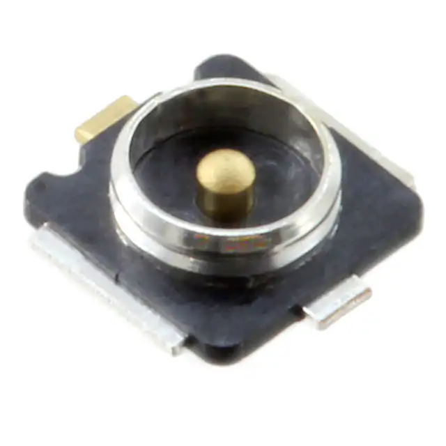
N.FL
U.FL-LP(V)
Fig.1
■Features
●N.FL Plug and Receptacle
1. Low profile
Nominal mated height is 1.4 mm (Max. 1.5 mm)
2. Small size: 7.7 mm2
N.FL-LP-040*
Plug
3. Light weight
4. Accepts high frequency transmission
of DC to 6 GHz.
3.4
Cable
Dia.0.81
Receptacle : 14 mg
Plug
: 28 mg
1.4(1.5MAX)
Sep.1.2019 Copyright 2019 HIROSE ELECTRIC CO., LTD. All Rights Reserved.
1.4(1.5MAX)
1.9(2.0MAX)
●Mated height comparison (With U.FL-LP(V) )
V.S.W.R. = 1.3 max. (DC to 6 GHz)
5. Board placement with automatic equipment
Receptacles are packaged in embossed carrier
tape and reel for automatic mounting.
N.FL-R-SMT-1
Receptacle
Fig.2
6. Plugs are terminated with ultra-fine
coaxial (fluorinated resin insulated) cable.
7. Special tool for an extraction
8. Verification of the fully mated condition
Tactile click sensation confirms fully mated
condition, assuring complete electrical and
mechanical connection.
9. Halogen-free*(Receptacle, plug(HF type))
*As defined by IEC61249-2-21
Br-900 ppm maximum, Cl-900 ppm maximum,
Cl+Br combined - 1,500 ppm maximum
■Applications
Mobile phones, wireless communication devices,
electronic measuring instruments, GPS, wireless
LAN, Bluetooth and any application requiring high
frequency transmission using small coaxial
connectors.
In cases where the application will demand a high level of reliability, such as automotive,
please contact a company representative for further information.
2014.10w
1
�N.FL Series●Lightweight SMT Miniature Coaxial Connectors – 1.4 mm Mated Height
■Specifications
Nominal characteristic impedance
50 ohms
Operating temperature range
DC to 6 GHz
Storage temperature range
-40°C to +90°C
(90% RH max.)
-30°C to +70°C
(90% RH max.)
Ratings
Frequency range
Item
1. Contact resistance
Specification
Center
contact: 25 m ohms max.
Outer
contact: 25 m ohms max.
Conditions
10 mA max.
2. Insulation resistance
500 M ohms min.
100V DC
3. Withstanding voltage
No flashover or insulation breakdown
200V AC / 1 minute
4. V.S.W.R.(Note)
1.3max.
DC to 6GHz
Contact resistance
5. Durability
Center
contact: 30 m ohms max.
Outer
contact: 30 m ohms max.
20 cycles
Sep.1.2019 Copyright 2019 HIROSE ELECTRIC CO., LTD. All Rights Reserved.
No damage, cracks, or parts dislocation
Frequency: 10 to 100 Hz, single amplitude of 1.5 mm
No electrical discontinuity of 1 µs or longer
6. Vibration
Acceleration: 59 m/s2, in each of 3 axis
No damage, cracks, or parts dislocation
7. Shock
5 cycles
No electrical discontinuity of 1 µs or longer
Acceleration of 735 m/s2, 11 ms continuous time
No damage, cracks, or parts dislocation
Waveform: sine half-wave, 3 cycles in each of the 3 axis
Insulation resistance: 100 M ohms min. (high humidity)
8. Humidity
Insulation resistance: 500 M ohms min. (dry)
96 hours at +40°C, and humidity of 95%
No damage, cracks, or parts dislocation
Temperature:-40°C/+5°C to +35°C/+90°C/+5°C to +35°C
9. Temperature cycle
No damage, cracks, or parts dislocation
Time: 30 min./ 5 min. max. / 30 min. / 5 min. max.
5 cycles
10. Salt spray test
No excessive corrosion
5% salt water solution, 48 hours
Note: Information contained in this catalog represents general requirements for this Series. Contact us for the drawings and
specifications for a specific part number shown.
* V.S.W.R. Measurement System
Measured as shown on the block diagram below.
Network Analyzer
Test Set
Test Port
D.U.T
Termination
Note1: N.FL Cable assembly (plug) is measured with SMA conversion
adapters mated with N.FL plugs at both ends of a 100cm coaxial
cable harness
Note2: N.FL receptacle, which is mounted on a 50 ohms glass epoxy
board, is measured with a SMA conversion adapter.
Test Port Cable
■Materials / Finishes
●Plugs-Right Angle
Shell
Part
Material
Phosphor bronze
Finish
Silver plated
Female center contact
Phosphor bronze
Gold plated
Insulator
PBT
Color: Black, UL94V-0
Color: Gray, UL94HB(HF type)
●Receptacle
Part
Shell
Male center contact
Insulator
2
Material
Phosphor bronze
Finish
Silver plated
Brass
Gold plated
LCP
Color: Black, UL94V-0
�N.FL Series●Lightweight SMT Miniature Coaxial Connectors – 1.4 mm Mated Height
■Cable Assembly(Plug)
2.8
N.FL-LP-040(06), N.FL-LP-040HF(06)(Applicable cable: outer diameter 0.81)
Sep.1.2019 Copyright 2019 HIROSE ELECTRIC CO., LTD. All Rights Reserved.
1.12
3.4
Ordering Information
[Plugs can be ordered only as terminated cable assemblies]
How To Specify Cable Assembly
[Double-ended cable assembly]
[Single-ended cable assembly]
L(mm)
L
L(mm)
L
Ordering Information
Ordering Information
Used Plug: N.FL-LP-040(06), N.FL-LP-040HF(06)
DoubleEnded
N.FL - 2LP HF6 - 04N 「」 TV - A - L
❶
SingleEnded
❷
N.FL - LP
❶
❷
❸
❹
❺
❻
❼
HF6 - 04N 「」 TV - A - L
❸
❶ Series name
N.FL
❷ Assembly type
LP : Single ended
❸ Environmental compliant
❹
❺
❻
❼
Standard tolerances for (L)
(L)mm
Standard Tolerance(mm)
2LP : Double ended
*L=35 to 200
±4
HF6 : Halogen-free plug
*L=200 to 500
±8
6 : Standard Plug
❹ Cable type
04N : 0.81mm dia. ultra-time coaxial cable
❺ Cable color
1:White 2:Black
*L=500 to 1000
±12
L=Longer than 1000
±1.5% of (L)
Note: Minimum available length(L) is 35mm.
❻ Cable outer conductor TV: Tin plated braided wire
Length(L)
❼ Total length (mm)
3
�N.FL Series●Lightweight SMT Miniature Coaxial Connectors – 1.4 mm Mated Height
■Receptacle
BRecommended PCB
mounting pattern
GND
GND
GND
No conductive
traces in this area
1.85
2
Ø2
2.05
0.8
0.25
SIG
GND
SIG
0.6
0.8
3.8
0.6
2.6
3
All dimensions: mm
Part No.
HRS No.
Packaging
N.FL-R-SMT-1(60)
331-0332-3 60
Reel (5,000 pcs/reel)
N.FL-R-SMT-1(80)
331-0332-3 80
Reel (10,000 pcs/reel)
RoHS
●Embossed Carrier Tape Dimensions (IEC 60286-3 compliant)
Embossed Carrier tape Dimensions
Ø330
4
.5
Unreeling direction
13.5
Material:PS(Black)
Ø1
2
Reel Dimensions
12
5.5
1.75
(N.FL-R-SMT-1(60) 8mm pitch)
A
8
A(SCALE FREE)
(N.FL-R-SMT-1(80) 4mm pitch)
2
4
.5
2
Ø13
Ø1
1.75
Unreeling direction
Ø2
1
12
5.5
Sep.1.2019 Copyright 2019 HIROSE ELECTRIC CO., LTD. All Rights Reserved.
1.8
2.6
3.1
1.9
4
All dimensions: mm
4
�N.FL Series●Lightweight SMT Miniature Coaxial Connectors – 1.4 mm Mated Height
■Conversion Adapters
●SMA Conversion Adapter (N.FL / U.FL side jack - SMA side plug)
(10.7)
Note: The FL side mating portions has a lower lock retention
force than the regular product, therefore, cannot be used
for purposes other than performance measurements.
8HEX
All dimensions: mm
HRS No.
311-0300-2 40
Part No.
HRMP-U.FLJ(40)
RoHS
Note: Applicable to both N.FL and U.FL.
●SMA Conversion Adapter (N.FL / U.FL side plug - SMA side jack)
14.05
(4.05)
Ø6.35
5.6
1/4-36UNS-2A
Note: The FL side mating portions has a lower lock retention
force than the regular product, therefore, cannot be used
for purposes other than performance measurements.
All dimensions: mm
Part No.
HRS No.
HRMJ-U.FLP(40)
311-0301-5 40
RoHS
Note: Applicable to both N.FL and U.FL.
●SMA Conversion Adapter
(18.3)
(4)
5.5
Ø6.35
6
1/4-36UNS-2A
Note: When mating with corresponding part (N.FL-RSMT-1) must be pressed down and held to make
complete connection.
All dimensions: mm
HRS No.
311-0423-2
Part No.
HRMJ-N.FLP-ST5
■Receptacle Inspection Adapter
Used for inspecting the performance
parameters of the cable assembly.
RoHS
12.9
(7.9)
(4.4)
7HEX
5
1
M5∞0.5
All dimensions: mm
HRS No.
331-0466-0
Part No.
U.FL-R-1
RoHS
Note: Applicable to both N.FL and U.FL.
Plug mating tool
Ø10
(12.9)
This tool is used for mating a plug.
JAPAN
8
For distinction with
W.FL-LP-IN.
All dimensions: mm
HRS No.
331-0334-9
Part No.
U.FL-LP-IN
RoHS
3
50
This jig is used for extraction from a mating condition.
Ø15
90
Plug extraction tool
U. FL/
2.1
Sep.1.2019 Copyright 2019 HIROSE ELECTRIC CO., LTD. All Rights Reserved.
6
All dimensions: mm
Part No.
U.FL-LP(V)-N-2
HRS No.
331-0493-2
RoHS
Note: Applicable to all the U.FL-LP(V)-040, U.FL-LP-062 and N.FL.
5
�N.FL Series●Lightweight SMT Miniature Coaxial Connectors – 1.4 mm Mated Height
■Usage Precautions
1. Plug
• Unmating
Insert the end of an extraction tool into a space between a plug and receptacle, and pull up
the tool in the perpendicular to a mounting surface of a receptacle, as shown in the figure.
●Recomended the use of the extraction tool for unmating.
U.FL-LP(V)-N-2
Extraction tool
Any attempt of unmating by pulling on the cable may
N.FL-LP-040
Plug
result in damage to the mechanical / electrical performance.
• Mating
Do not attempt to insert on an extreme angle.
(1) Mating / unmating
N.FL-LP-040
Plug
(2) Pull forces on the
cable after connectors
are mated
Sep.1.2019 Copyright 2019 HIROSE ELECTRIC CO., LTD. All Rights Reserved.
N.FL-R-SMT-1
Receptacle
2.9N max.
Do not apply any pull forces after the bending
of the cable.
N.FL-R-SMT-1
Receptacle
(3) Precautions
Do not twist connectors excessively during mating / unmating.
2. Receptacle
250 ç max. for
10 seconds
[ç]
260
240
220
200
180
160
140
120
100
80
(1) Recommended reflow
temperature profile
Preheat
(130 to 180ç)
120 seconds max.
230ç
220ç
50 seconds max.
60 seconds max.
Time
q The temperature profile indicates the board surface temperature at the point of contacts with the connector
leads.
w In individual applications the actual temperature may vary, depending on the solder paste type, volume /
thickness and board size / thickness. Consult your solder paste and equipment manufacturer for the
detailed recommendations.
(2) Manual soldering
Soldering iron temperature: 350°C, Soldering time: for 5 seconds max.
(3) Recommended metal
mask thickness
0.1 mm to 0.12 mm
(4) Reflow cycles
2 times
3. Operating environment and storage conditions
(1) Operating environment
(2) Storage conditions Receptacle
The connectors are not designed to operate in the following environments:
• Exposed to a excessive amounts of fine particles and dust
• Regions and places having a high density of sulfur dioxide, hydrogen sulfide, nitrogen dioxide or other corrosive
gasses.
• Environments having large rapid variations in temperature.
Store in the Hirose Electric packaging.
Temperature: -10 to +40ç, Humidity: 85% max.
Use within 6 months of delivery.
Receptacles for which the storage period has elapsed must be tested for solderability to the PC board
mounting surface.
®
6
2-6-3,Nakagawa Chuoh,Tsuzuki-Ku,Yokohama-Shi 224-8540,JAPAN
TEL: +81-45-620-3526 Fax: +81-45-591-3726
http://www.hirose.com
http://www.hirose-connectors.com
The characteristics and the specifications contained herein are for reference purpose. Please refer to the latest customer drawings prior to use.
The contents of this catalog are current as of date of 10/2014. Contents are subject to change without notice for the purpose of improvements.
�


 工商网监
湘ICP备2023018690号
工商网监
湘ICP备2023018690号
