MCR100 Series
Silicon Controlled Rectifiers
Features
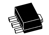
SOT-89
Sensitive gate silicon controlled rectifiers
Reverse blocking thyristors
Equivalent Circuit
1.Cathode(K) 2.Anode(A)3.Gate(G)
Marking Code :
MCR100-4SQ : MCR100-4
MCR100-6SQ : MCR100-6
MCR100-8SQ : MCR100-8
Absolute Maximum Ratings
Ratings at 25℃ ambient temperature unless otherwise specified.
Parameter
Peak Repetitive Off-State Voltage
Note1
Symbol
MCR100-6SQ
Gate Open)
MCR100-8SQ
On-State RMS Current
Unit
200
MCR100-4SQ
(TJ = -40°C~110°C, Sine Wave,50 to 60 Hz,
Value
VDRM,VRRM
400
V
600
IT(RMS)
0.8
A
ITSM
8
A
I2t
0.415
A2s
PGM
0.1
W
PG(AV)
0.1
W
Peak Gate Current – Forward (Pulse Width ≤ 1 μs)
IGM
1
A
Peak Gate Voltage – Reverse (Pulse Width ≤ 1 μs)
VGRM
5
V
TJ
-40 to +110
°C
TSTG
-40 to +150
°C
Peak Non-Repetitive Surge Current
(1/2 Cycle, Sine Wave, 60 Hz, TJ = 25°C)
Circuit Fusing Considerations (t = 8.3ms)
Forward Peak Gate Power (Pulse Width ≤ 1 μs)
Forward Average Gate Power (t = 8.3ms)
Operating Junction Temperature Range
Storage Temperature Range
Note:
1.VDRM and VRRM for all types can be applied on continous basis. Ratings apply for zero negative gate voltage; however,positive
gate voltage shall not be applied concurrent with negative potential on the anode. Blocking voltages shall not be tested with a
constant current sourse such that the voltage ratings of the devices are exceeded.
www.pingjingsemi.com
Revision:2.0 Oct-2021
1/6
�MCR100 Series
Silicon Controlled Rectifiers
Electrical Characteristics (TA=25℃)
Parameter
Peak Forward or Reverse Blocking Current
Note2
at VD = Rated VDRM and VRRM, RGK =1KΩ
Peak Forward On-State Voltage
Note1
at ITM = 0.8 A
Gate Trigger Current Note3
at VAK = 7 V, RL = 100 Ω
Holding Current
Note2
at VAK = 7 V, Initiating Current = 20 mA
Latch Current
at VAK = 7 V, Ig = 1 mA
TC = 25°C
TC = -40°C
TC = 25°C
TC = -40°C
Gate Trigger Voltage Note3
TC = 25°C
at VAK = 7 V, RL = 100 Ω
TC = -40°C
Symbol
Value
Unit
IDRM,IRRM
10
μA
VTM
1.7
V
IGT
200
μA
IH
IL
VGT
5
10
10
15
0.8
1.2
mA
mA
V
Note:
1.Indicates pulse test width ≤ 1 ms, duty cycle ≤1%
2.RGK = 1 KΩ included in measurement
3.Does not include RGK in measurement
www.pingjingsemi.com
Revision:2.0 Oct-2021
2/6
�MCR100 Series
Silicon Controlled Rectifiers
VGT Gate Trigger Voltage (V)
IGT Gate Trigger Current (μA)
Typical Characteristic Curves
TJ Junction Temperature (℃)
IL Latch Current (μA)
IH Holding Current (μA)
TJ Junction Temperature (℃)
TJ Junction Temperature (℃)
TC Case Temperature (℃)
IT Instantaneous On-State Current (A)
TJ Junction Temperature (℃)
IT(RMS) On-State RMS Current (A)
www.pingjingsemi.com
Revision:2.0 Oct-2021
Maximum TJ =25℃
Maximum TJ =110℃
VT Instantaneous On-State Voltage (V)
3/6
�MCR100 Series
Silicon Controlled Rectifiers
Package Outline
SOT-89
Dimensions in mm
Ordering Information
Device
Package
Shipping
MCR100 Series
SOT-89
3,000PCS/Reel&13inches
www.pingjingsemi.com
Revision:2.0 Oct-2021
4/6
�MCR100 Series
Silicon Controlled Rectifiers
Conditions of Soldering and Storage
Recommended condition of reflow soldering
Recommended peak temperature is over 245 OC. If peak temperature is below 245 OC, you may adjust
the following parameters:
Time length of peak temperature (longer)
Time length of soldering (longer)
Thickness of solder paste (thicker)
Conditions of hand soldering
Temperature: 370 OC
Time: 3s max.
Times: one time
Storage conditions
Temperature
5 to 40 OC
Humidity
30 to 80% RH
Recommended period
One year after manufacturing
www.pingjingsemi.com
Revision:2.0 Oct-2021
5/6
�MCR100 Series
Silicon Controlled Rectifiers
Package Specifications
The method of packaging
3,000 pcs per reel
SOT-89
9,000 pcs per box
3 reels per box
36,000 pcs per carton
4 boxes per carton
Embossed tape and reel data
B
A
T
symbol
E
D
F
A
B
C
D
E
F
T
Value(unit:mm)
φ330±1
12.7±0.5
16.5±0.3
φ99.5±0.5
φ13.6±0.3
2.8±0.3
1.9±0.2
C
Reel (13'')
www.pingjingsemi.com
Revision:2.0 Oct-2021
6/6
�
很抱歉,暂时无法提供与“MCR100-8SQ”相匹配的价格&库存,您可以联系我们找货
免费人工找货