Circuit Protection
Rev. 2016051260A0.1
CAN BUS ESD Protection
TVS Diode Array
PTT233G20M15B40
AEC-Q101
Qualified
Features
Low Leakage Current
Low Clamping Voltages
Response Time is Typically < 1 ns
AEC-Q101 Automotive Grade Certified
Lead free and RoHS compliant
IEC Compatibility:
IEC 61000-4-2, ±30kV contact, ±30kV air
IEC 61000-4-4, 40A (5/50ns)
IEC 61000-4-5, Lightning, 11A (8/20µs)
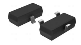
SOT23-3L
Pin 1
Pin 3
Appications
Pin 2
CAN Bus Protection
Automotive Applications
Control & Monitoring Systems
Servers, Notebook, and Desktop PC
Pinout and Functional Block Diagram
Control & Monitoring Systems
Absolute Maximum Ratings
Parameter
Symbol
Value
Units
Peak Pulse Power (tp=8/20µs)
PPP
400
W
Peak Pulse Current (tp=8/20µs)
IPP
11
A
Operating Temperature
TJ
-40 to 125
°C
Storage Temperature
TSTG
-40 to 125
°C
Note:
CAUTION: Stresses above those listed in “Absolute Maximum Ratings” may cause permanent damage to the component. This is a stress only
rating and operation of the component at these or any other conditions above those indicated in the operational sections of this specification is
not implied.
Electrical Characteristics ( TA = 25°C unless otherwise noted )
Parameter
Symbol
Test Conditions
Reverse Standoff Voltage
VRWM
IR≤1μA, Pin1 or Pin2 to Pin3
Breakdown Voltage
VBR
IR=1mA, Pin1 or Pin2 to Pin3
Leakage Current
IR
VR=24V
Clamp VoltageⅠ
VC
IPP=6A, tp=8/20µs, Pin 1 or Pin 2 to Pin 3
35.0
Dynamic ResistanceⅡ
RDYN
TLP, tp=100ns, I/O to GND
0.5
IEC 61000-4-2 ( Contact )
±30
kV
ESD Withstand VoltageⅠ
VESD
IEC 61000-4-2 ( Air )
±30
kV
Junction Capacitance
Cj
Reverse Bias=0V, f=1MHz; Pin 1 or Pin 2 to Pin 3
25.0
pF
Min
16.7
Typ
18.5
IPP=1A, tp=8/20µs, Pin 1 or Pin 2 to Pin 3
Note:
Ⅰ Parameter is guaranteed by design and/or component characterization.
Ⅱ Transmission Line Pulse (TLP) with 100ns width, 2ns rise time, and average window t1=70ns to t2= 90ns
1 of 4
www.prosemitech.com
20.0
Max
Units
15.0
V
20.0
V
0.5
μA
25.0
V
43.0
V
Ω
�Circuit Protection
PTT233G20M15B40
Typical Characteristics
Figure 1: Peak Pulse Power vs. Pulse Time
Figure 2: Power Derating Curve
110
100
Percent of Rated Power for Ipp
Ppp – Peak Pulse Power - Ppp(KW)
10
400w 8/20µs aveform
1
0.1
0.01
0.1
1
10
100
90
80
70
60
50
40
30
20
10
0
1,000
0
25
td – Pulse Duration - µs
Figure3: Pulse Waveform
90
125
40
70
e-1
50
40
td=Ipp/2
20
30
25
20
Test
Waveform
Paramters
tr=8µs
td=20µs
15
10
5
10
0
0
0
5
10
15
20
25
30
Time (µs)
0
2
4
8
6
10
Peak Pulse Current–IPP (A)
Soldering Parameters
IR Reflow Profile
tP
Temperature
TP
T C -5°C
Max.Ramp Up Rate= 3 °C /S
Max.Ramp Down Rate= 6°C/S
TL
TS
t
max
Preheat Heat
Temperature min (Tsmin)
Temperature max(Tsmax)
Time (Tsmin to Tsmax) (ts)
150 °C
200°C
60 -120 seconds
Average ramp-up rate
(Tsmax to Tp)
3°C/second max.
Liquidous temperature (T L )
Time at liquidous (t L )
217 °C
60 - 150 seconds
Preheat
TS
min
tS
25
Time 25 °C to Peak
Wave Soldering: 260°C, 10 seconds max.
Infrared Reflow: 260°C, 30 seconds max.
2 of 4
150
35
Clamping Voltage–VC (V)
Ipp
80
Percent
100
45
Waveform
Paramters
tr=8µs
td=20µs
100
30
75
Figure 4: Clamping Voltage vs.Ipp
110
60
50
Ambient Temperature - TA (℃)
www.prosemitech.com
Time
Peak temperature(Tp)
260+0/-5°C
Time within 5°C of actual
peak Temperature (tp)
10 – 30 seconds
Average ramp-down rate
(Tp to Tsmax)
6°C/second max.
Time 25 °C to peak
temperature
8 minutes max.
12
�Circuit Protection
PTT233G20M15B40
Package Dimensions
D
Symbol
3
A
A1
A2
b
c
D
E
E1
e
e1
L
θ
E1 E
1
2
e
b
e1
A
A2
A1
Millimeters
Min
0.90
0.00
0.60
0.30
0.08
2.80
2.25
1.20
0.95 BSC
1.80
0.30
0o
Max
1.15
0.10
0.70
0.50
0.15
3.00
2.55
1.40
2.00
0.50
8o
0.25
θ
c
L
b
Symbol
M
C
Z
e
e1
b
M
Z
C
e
e1
Part Marking
BB2
Package Information
Part Number
PTT233G20M15B40
3 of 4
Package
SOT23-3L
www.prosemitech.com
Packing Quantity
3,000 pcs
Delivery mode
Tape and Reel
Millimeters
2.02
0.80
2.82
0.95 BSC
1.9 BSC
0.80
Inches
0.0795
0.0315
0.111
0.037 BSC
0.075 BSC
0.0315
Inches
Min
0.035
0.000
0.0236
0.012
0.003
0.110
0.089
0.047
0.0374 BSC
0.071
0.012
0o
Max
0.045
0.004
0.0275
0.020
0.006
0.118
0.100
0.055
0.079
0.020
8o
�Circuit Protection
PTT233G20M15B40
The PTT233G20M15B40 can protect automotive Controller Area Network (CAN) lines against damages caused by electrostatic discharge
(ESD), electrical fast transient (EFT) and other transients. The PTT233G20M15B40 can absorb repetitive ESD impact above the maximum
level stipulated in the international standard IEC 61000-4-2 without performance degradation and can safely withstand 3A surge (8/20
waveshape as defined in IEC 61000-4-5 2nd edition) at a very low clamping voltages.The PTT233G20M15B40 can be used for highspeed
and fault-tolerant CAN buses.
SPLIT
CANH
R T/2
CAN BUS
Transceiver
CAN
BUS
R T/2
CANL
Common
Mode Choke
(optional)
CG
PTT233G20M15B40
© 2017 PROSEMI Inc. All Rights Reserved.
Specifications and features are subject to
change without notice.
The PROSEMI logo, and all other PROSEMI
trademarks are the property of PROSEMI Inc.
All other trademarks are the property of their
respective owners.
4 of 4
www.prosemitech.com
�
很抱歉,暂时无法提供与“PTT233G20M15B40”相匹配的价格&库存,您可以联系我们找货
免费人工找货