CSR/CSRN Series
Stackpole Electronics, Inc.
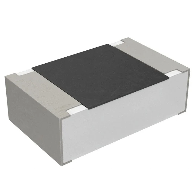
Thick Film Current Sensing Resistor
Features:
•
•
•
•
•
•
Resistive Product Solutions
0402 to 1225 sizes available
Power ratings to 3W
Low inductance – less than 0.2nH typically
RoHS compliant and halogen-free
Non-standard resistance values available
0815, 2010 and 2512 sizes available with narrow
terminations (CSRN)
Electrical Specifications - CSR
Resistance
Temperature
Coefficient
±200 ppm/ºC
±300 ppm/ºC
±200 ppm/ºC
Type / Code
Power Rating (Watts)
@ 70ºC
Dielectric Withstanding
Voltage
CSR0402
CSR0603
CSR0805
CSR1206
0.125W
0.125W
0.25W
0.5W
200V
200V
200V
200V
CSR1210
0.5W
200V
CSR0830
2W
200V
CSR2010
CSR2512
1W
2W
200V
200V
±100 ppm/ºC (1)
±200 ppm/ºC
200V
±300 ppm/ºC
±200 ppm/ºC
±150 ppm/ºC
±100 ppm/ºC
CSR1225
3W
Ohmic Range (Ω) and Tolerance
1%
±100 ppm/ºC (1)
±600 ppm/ºC
±400 ppm/ºC
±300 ppm/ºC
±200 ppm/ºC
±300 ppm/ºC
±200 ppm/ºC
±150 ppm/ºC
-
2%, 5%
0.05 - 1
0.02 - 1
0.02 - 1
0.01 - 1
0.01 - 0.02
0.021 - 0.05
0.051 - 0.099
0.1 - 1
0.001 - 0.004
0.005 - 0.01
0.011 - 0.35
0.01 - 1
0.01 - 1
0.003 - 0.005
0.006 - 0.02
0.021 - 0.03
0.033 - 8
(1) Contact Factory for TCR below 50mOhm
Electrical Specifications – CSRN (Narrow Termination)
Power Rating (Watts)
@ 70ºC
Dielectric Withstanding
Voltage
CSRN0815
1W
200V
CSRN2010
1W
2W
200V
200V
Type / Code
CSRN2512(*)
(*) AEC-Q200 Qualified
Resistance
Temperature
Coefficient
±300 ppm/ºC
±150 ppm/ºC
±250 ppm/ºC
±200 ppm/ºC
Ohmic Range (Ω) and Tolerance
1%
2%, 5%
0.01 - 0.019
0.02 - 0.5
0.01 - 1
0.01 - 1
Electrical Specifications – CSR-HP (High Power)
Type / Code
Power Rating (Watts)
@ 70ºC
Dielectric Withstanding
Voltage
CSR0603…-HP
0.2W
200V
CSR1210…-HP
0.75W
200V
Resistance
Temperature
Coefficient
Ohmic Range (Ω) and Tolerance
±400 ppm/ºC
±300 ppm/ºC
±200 ppm/ºC
±600 ppm/ºC
0.051 - 0.1
0.102 - 0.5
0.51 - 1
0.01 - 0.02
1%, 2%, 5%
±400 ppm/ºC
0.021 - 0.05
±300 ppm/ºC
0.051 - 0.091
±200 ppm/ºC
0.1 - 1
Please refer to the High Power Resistor Application Note (page 5) for more information on designing and implementing high power
resistor types.
Rev Date: 12/28/2018
This specification may be changed at any time without prior notice
Please confirm technical specifications before you order and/or use.
1
www.seielect.com
marketing@seielect.com
�CSR/CSRN Series
Stackpole Electronics, Inc.
Thick Film Current Sensing Resistor
Resistive Product Solutions
Mechanical Specifications
L
Body Length
0.039 ± 0.002
1.00 ± 0.05
W
Body Width
0.020 ± 0.002
0.50 ± 0.05
H
Body Height
0.013 ± 0.004
0.32 ± 0.10
a
Top Termination
0.010 ± 0.004
0.25 ± 0.10
CSR0603
0.063 ± 0.004
1.60 ± 0.10
0.031 ± 0.004
0.80 ± 0.10
0.018 ± 0.004
0.45 ± 0.10
0.012 ± 0.008
0.30 ± 0.20
0.012 ± 0.008
0.30 ± 0.20
inches
mm
CSR0805
0.079 ± 0.006
2.00 ± 0.15
0.049 ± 0.006
1.25 ± 0.15
0.022 ± 0.004
0.55 ± 0.10
0.012 ± 0.008
0.30 ± 0.20
0.016 ± 0.010
0.40 ± 0.25
inches
mm
CSR1206
0.120 ± 0.006
3.05 ± 0.15
0.061 ± 0.006
1.55 ± 0.15
0.022 ± 0.004
0.55 ± 0.10
0.020 ± 0.012
0.50 ± 0.30
0.016 ± 0.010
0.40 ± 0.25
inches
mm
CSR1210
0.122 ± 0.004
3.10 ± 0.10
0.102 ± 0.006
2.60 ± 0.15
0.022 ± 0.004
0.55 ± 0.10
0.020 ± 0.012
0.50 ± 0.30
0.020 ± 0.010
0.50 ± 0.25
inches
mm
CSR0830
0.079 ± 0.008
2.00 ± 0.20
0.295 ± 0.012
7.50 ± 0.30
0.024 ± 0.004
0.60 ± 0.10
0.016 ± 0.008
0.40 ± 0.20
0.016 ± 0.008
0.40 ± 0.20
inches
mm
CSR2010
0.197 ± 0.008
5.00 ± 0.20
0.100 ± 0.008
2.54 ± 0.20
0.020 ± 0.006
0.50 ± 0.15
0.068 ± 0.006
1.72 ± 0.15
0.067 ± 0.006
1.70 ± 0.15
inches
mm
CSR2512
0.252 ± 0.008
6.40 ± 0.20
0.126 ± 0.008
3.20 ± 0.20
0.020 ± 0.006
0.50 ± 0.15
0.075 ± 0.006
1.90 ± 0.15
0.075 ± 0.006
1.90 ± 0.15
inches
mm
Type / Code
CSR0402
b
Unit
Bottom Termination
0.008 ± 0.004
inches
0.20 ± 0.10
mm
Mechanical Specifications – CSRN (Narrow Termination)
L
Body Length
0.079 ± 0.008
2.00 ± 0.20
W
Body Width
0.148 ± 0.008
3.75 ± 0.20
H
Body Height
0.024 ± 0.004
0.60 ± 0.10
a
Top Termination
0.016 ± 0.008
0.40 ± 0.20
CSRN2010
0.197 ± 0.008
5.00 ± 0.20
0.096 ± 0.006
2.45 ± 0.15
0.024 ± 0.006
0.60 ± 0.15
0.024 ± 0.012
0.60 ± 0.30
0.020 ± 0.010
0.50 ± 0.25
inches
mm
CSRN2512
0.250 ± 0.008
6.35 ± 0.20
0.124 ± 0.006
3.15 ± 0.15
0.024 ± 0.004
0.60 ± 0.10
0.024 ± 0.012
0.60 ± 0.30
0.022 ± 0.010
0.55 ± 0.25
inches
mm
Type / Code
CSRN0815
b
Unit
Bottom Termination
0.016 ± 0.008
inches
0.40 ± 0.20
mm
Mechanical Specifications – CSR1225
Type / Code
A
B
C
D
E
F
Unit
CSR1225
0.024 ± 0.012
0.60 ± 0.30
0.254 ± 0.006
6.45 ± 0.15
0.126 ± 0.006
3.20 ± 0.15
0.031 ± 0.010
0.80 ± 0.25
0.035 ± 0.006
0.90 ± 0.15
0.090 ± 0.005
2.29 ± 0.13
inches
mm
Rev Date: 12/28/2018
This specification may be changed at any time without prior notice
Please confirm technical specifications before you order and/or use.
2
www.seielect.com
marketing@seielect.com
�CSR/CSRN Series
Stackpole Electronics, Inc.
Thick Film Current Sensing Resistor
Resistive Product Solutions
Recommended Pad Layouts - CSR
Type / Code
CSR0402
CSR0603
CSR0805
CSR1206
CSR1210
CSR0830
CSR2010
CSR2512
CSR1225
A
B
0.020
0.50
0.031
0.80
0.039
1.00
0.079
2.00
0.079
2.00
0.039
1.00
0.142
3.60
0.193
4.90
0.047
1.20
0.020
0.50
0.039
1.00
0.039
1.00
0.045
1.15
0.045
1.15
0.071
1.80
0.055
1.40
0.063
1.60
0.079
2.00
C
0.024
0.60
0.035
0.90
0.053
1.35
0.067
1.70
0.098
2.50
0.299
7.60
0.098
2.50
0.126
3.20
0.276
7.00
±
±
±
±
±
±
±
±
±
±
±
±
±
±
±
±
±
±
Unit
0.008
0.20
0.008
0.20
0.008
0.20
0.008
0.20
0.008
0.20
0.008
0.20
0.008
0.20
0.008
0.20
0.008
0.20
inches
mm
inches
mm
inches
mm
inches
mm
inches
mm
inches
mm
inches
mm
inches
mm
inches
mm
0.008
0.20
0.008
0.20
0.008
0.20
inches
mm
inches
mm
inches
mm
Recommended Pad Layouts - CSRN
Type / Code
CSRN0815
CSRN2010
CSRN2512
A
B
0.039
1.00
0.142
3.60
0.193
4.90
0.071
1.80
0.055
1.40
0.063
1.60
C
0.154
3.90
0.098
2.50
0.126
3.20
±
±
±
±
±
±
Unit
Performance Characteristics
Test
Test Method
High Temperature
Exposure
MIL-STD-202 Method 108
Short Time Overload
JIS-C-5201-1 4.13
IEC 60115-1 4.13
Test Specification
Typical
Test Condition
1% Tol: (±1.0% +0.05Ω)
2%, 5% Tol:(±1.5% +0.10Ω)
≤ 0.5%
1000 hrs. @ T=155°C. Unpowered. Measurement
at 24 ± 4 hours after test conclusion.
±(0.5% +0.05Ω)
≤ 0.25%
±(1.0% +0.05Ω)
For high power rating
≤ 0.5%
RCV(rated current)*2.5 for 5 seconds.
JESD22 Method JA-104
1% Tol: (±0.5% +0.05Ω)
2%, 5% Tol:(±1.5% +0.10Ω)
≤ 0.5%
Biased Humidity
MIL-STD-202 Method 103
1% Tol: (±1.00% +0.10Ω)
2%, 5% Tol:(±2.00% +0.10Ω)
≤ 0.5%
Operational Life
MIL-STD-202 Method 108
1% Tol: (±1.00% +0.10Ω)
2%, 5% Tol:(±2.00% +0.10Ω)
≤ 0.5%
External Visual
MIL-STD 883 Method 2009
--
Pass
Temperature
Cycling
Rev Date: 12/28/2018
This specification may be changed at any time without prior notice
Please confirm technical specifications before you order and/or use.
3
1000 Cycles (-55°C to +125°C) Measurement at
24 ± 4 hours after test conclusion.
30 min maximum dwell time at each temperature
extreme. 1 min. maximum transition time.
1000 hours 85°C/85% RH. Note: Specified conditions:
10% of operating power. Measurement at 24 ± 4
hours after test conclusion.
Condition D Steady State TA=125°C at rated power.
Measurement at 24 ± 4 hours after test conclusion.
Electrical test not required. Inspect device
construction, marking and workmanship.
www.seielect.com
marketing@seielect.com
�CSR/CSRN Series
Stackpole Electronics, Inc.
Thick Film Current Sensing Resistor
Resistive Product Solutions
Performance Characteristics (cont.)
Test
Physical
Dimensions
Resistance to
Solvents
Mechanical
Shock
Test Method
Test Specification
JESD22 Method JB-100
Typical
--
Pass
MIL-STD 202 Method 215
Marking unsmeared
MIL-STD 202 Method 213
1% Tol: (±0.25% +0.05Ω)
2%, 5% Tol:(±1.00% +0.05Ω)
Vibration
MIL-STD 202 Method 204
1% Tol: (±0.50% +0.05Ω)
2%, 5% Tol:(±1.00% +0.05Ω)
≤ 0.5%
Resistance to
Soldering Heat
MIL-STD 202 Method 210
1% Tol: (±0.50% +0.05Ω)
2%, 5% Tol:(±1.00% +0.05Ω)
≤ 0.5%
ESD
AEC-Q200-002
--
Pass
Solderability
J-STD-002
> 95% Coverage
Pass
Electrical
Characterization
User Spec
--
Pass
Flammability
UL-94
Board Flex
AEC-Q200-005
Terminal Strength
(SMD)
Flame
Retardance
Pass
Test Condition
Verify physical dimensions to the applicable device
detail specification. Note: User(s) and Suppliers spec.
Electrical test not required.
Note: Aqueous wash chemical - OKEM Clean or
equivalent. Do not use banned solvents.
≤ 0.5%
No ignition of tissue or scorching
of pine board.
1% Tol: (±1.00% +0.05Ω)
2%, 5% Tol:(±1.00% +0.05Ω)
Pass
Figure 1 of Method 213. Condition C.
5 g's for 20 min., 12 cycles each of 3 orientations.
Note: Use 8"X5" PCB 0.031" thick 7 secure points on
one long side and 2 secure points at corners of
opposite sides. Parts mounted within 2" from any
secure point. Test from 10 - 2000 Hz.
Condition B no pre-heat of samples. Note: Single
wave solder - Procedure 2 for SMD.
With the electrometer in direct contact with the
discharge tip, verify the voltage setting at levels
of ±500 V, ±1kV, ±2kV, ±4kV, ±8kV.
The electrometer reading shall be within ±10%
for voltages from 500 V to ≤ 8 kV.
Electrical test not required. Magnification 50X.
Conditions:
SMD:
a) Method B, 4 hrs @ 155°C dry heat @ 235°C.
b) Method B @ 215°C category 3.
c) Method D category 3 @ 260°C.
Parametrically test per lot and sample size
requirements, summary to show Min, Max, Mean and
Standard Deviation at room as well as Min and Max
operating temperatures.
V-0 or V-1 are acceptable.
Electrical test not required.
≤ 0.5%
AEC-Q200-006
None broken
Pass
AEC-Q200-001
No flame
Pass
60 second minimum holding time.
Operating Temperature Range: -55ºC to +155ºC
Power Derating Curve:
Percent Rated Power (%)
100
-55ºC
70ºC
80
60
40
20
155ºC
0
-60
0
20
40
60
80
100
120
140
160
180
Ambient Temperature (ºC)
Rev Date: 12/28/2018
This specification may be changed at any time without prior notice
Please confirm technical specifications before you order and/or use.
4
www.seielect.com
marketing@seielect.com
�CSR/CSRN Series
Stackpole Electronics, Inc.
Thick Film Current Sensing Resistor
Resistive Product Solutions
High Power Chip Resistors and Thermal Management
Stackpole has developed several surface mount resistor series in addition to our current sense resistors, which have had
higher power ratings than standard resistor chips. This has caused some uncertainty and even confusion by users as to
how to reliably use these resistors at the higher power ratings in their designs.
The data sheets for the RHC, RMCP, RNCP, CSR, CSRN, CSRF, CSS, and CSSH state that the rated power assumes
an ambient temperature of no more than 100°C for the CSS / CSSH series and 70°C for all other high power resistor
series. In addition, IPC and UL best practices dictate that the combined temperature on any resistor due to power
dissipated and ambient air shall be no more than 105°C. At first glance this wouldn’t seem too difficult, however the graph
below shows typical heat rise for the CSR ½ 100 milliohm at full rated power. The heat rise for the RMCP and RNCP
would be similar. The RHC with its unique materials, design, and processes would have less heat rise and therefore
would be easier to implement for any given customer.
The 102°C heat rise shown here would indicate there will be additional thermal reduction techniques needed to keep this
part under 105°C total hot spot temperature if this part is to be used at 0.75 watts of power. However, this same part at
the usual power rating for this size would have a heat rise of around 72°C. This additional heat rise may be dealt with
using wider conductor traces, larger solder pads and land patterns under the solder mask, heavier copper in the
conductors, via through PCB, air movement, and heat sinks, among many other techniques. Because of the variety of
methods customers can use to lower the effective heat rise of the circuit, resistor manufacturers simply specify power
ratings with the limitations on ambient air temperature and total hot spot temperatures and leave the details of how to best
accomplish this to the design engineers. Design guidelines for products in various market segments can vary widely so
it would be unnecessarily constraining for a resistor manufacturer to recommend the use of any of these methods over
another.
Note:
The final resistance value can be affected by the board layout and assembly process, especially the size of the
mounting pads and the amount of solder used. This is especially notable for resistance values ≤ 50mΩ.
This should be taken into account when designing.
Rev Date: 12/28/2018
This specification may be changed at any time without prior notice
Please confirm technical specifications before you order and/or use.
5
www.seielect.com
marketing@seielect.com
�CSR/CSRN Series
Stackpole Electronics, Inc.
Thick Film Current Sensing Resistor
Resistive Product Solutions
RoHS Compliance
Stackpole Electronics has joined the worldwide effort to reduce the amount of lead in electronic components and to meet the various
regulatory requirements now prevalent, such as the European Union’s directive regarding “Restrictions on Hazardous Substances”
(RoHS 3). As part of this ongoing program, we periodically update this document with the status regarding the availability of our
compliant components. All our standard part numbers are compliant to EU Directive 2011/65/EU of the European Parliament as
amended by Directive (EU) 2015/863/EU as regards the list of restricted substances.
RoHS Compliance Status
Standard
Product
Series
CSR
CSRN
Package /
Termination
Type
Description
Thick Film Current Sensing
Surface Mount Chip Resistor
Thick Film Current Sensing
Surface Mount Chip Resistor, Narrow
Standard Series
RoHS Compliant
YES by means of
exemption 7c-I
YES by means of
exemption 7c-I
SMD
SMD
Lead-Free
Lead-Free
Effective Date
Mfg. Effective Date
Code
(Std Product Series)
(YY/WW)
Lead-Free Termination
Composition
100% Matte Sn over Ni
May-04
04/18
100% Matte Sn over Ni
May-04
04/18
“Conflict Metals” Commitment
We at Stackpole Electronics, Inc. are joined with our industry in opposing the use of metals mined in the “conflict region” of the eastern
Democratic Republic of the Congo (DRC) in our products. Recognizing that the supply chain for metals used in the electronics industry
is very complex, we work closely with our own suppliers to verify to the extent possible that the materials and products we supply do
not contain metals sourced from this conflict region. As such, we are in compliance with the requirements of Dodd-Frank Act regarding
Conflict Minerals.
Compliance to “REACH”
We certify that all passive components supplied by Stackpole Electronics, Inc. are SVHC (Substances of Very High Concern) free and
compliant with the requirements of EU Directive 1907/2006/EC, “The Registration, Evaluation, Authorization and Restriction of
Chemicals”, otherwise referred to as REACH. Contact us for complete list of REACH Substance Candidate List.
Environmental Policy
It is the policy of Stackpole Electronics, Inc. (SEI) to protect the environment in all localities in which we operate. We continually strive
to improve our effect on the environment. We observe all applicable laws and regulations regarding the protection of our environment
and all requests related to the environment to which we have agreed. We are committed to the prevention of all forms of pollution.
How to Order
1
2
3
4
5
6
7
8
9
10
11
12
13
C
S
R
1
2
0
6
F
T
1
0
L
0
Product Series
Code Description
Standard
CSR
Narrow
CSRN
Terminations
Size
Code Power
0402 0.125W
0603 0.125W
0805 0.25W
1206 0.5W
1210 0.5W
0815
1W
0830
2W
2010
1W
2512
2W
1225
3W
Tolerance
Code Tol
F
1%
G
2%
J
5%
Code
T
K
Packaging
Size
0402
0603, 0805, 1206, 1210
2010, 2512
0815, 0830, 1225
0402
0603, 0805, 1206, 1210
2010, 2512
0815, 0830, 1225
Description
7" Reel
Paper Tape
7" Reel
Plastic Tape
7" Reel
Paper Tape
7" Reel
Plastic Tape
Rev Date: 12/28/2018
This specification may be changed at any time without prior notice
Please confirm technical specifications before you order and/or use.
6
-
Resistance Value
Quantity
10,000
5,000
4,000
2,000
1,000
Four characters with the
multiplier used as the
decimal holder.
"L" used as multiplier of
10-3 for any value
under 0.1 ohm
14
15
H
P
Special (*)
Code Description
-HP High Power
(*) Only available
for 0603 and 1210
sizes
0.051 ohm = 51L0
0.35 ohm = R350
1 ohm = 1R00
www.seielect.com
marketing@seielect.com
�


 工商网监
湘ICP备2023018690号
工商网监
湘ICP备2023018690号
