BSS138
50V N-Channel Enhancement Mode MOSFET
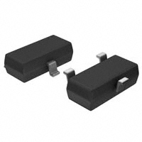
SOT-23
3
V(BR)DSS
ID
RDS(on)MAX
2.5Ω@10V
50V
3.0Ω@4.5V
1. Gate
2. Source
340mA
3. Drain
2
1
Features
Application
● Trench Power MV MOSFET technology
● Voltage controlled small signal switch
● Low input Capacitance
● Fast Switching Speed
● Low Input / Output Leakage
● Battery operated systems
● Solid-state relays
● Direct logic-level interface:TTL/CMOS
Marking
Equivalent Circuit
D
SS
G
XXX
XXX:Date Code
S
Absolute Maximum Ratings (TA=25℃unless otherwise noted)
Parameter
Symbol
Value
Unit
Drain-Source Voltage
VDS
50
V
Gate-Source Voltage
VGS
±20
V
Continuous Drain Current
ID
340
mA
Pulsed Drain Current (Note 1)
IDM
1.5
A
PD
350
mW
RθJA
357
℃/W
TJ,Tstg
-50 ~150
Power Dissipation(Note 2)
Thermal Resistance from Junction to Ambient(Note 2)
Junction Temperature and Storage Temperature
℃
Notes: Stresses exceeding Maximum Ratings may damage the device. Maximum Ratings are stress ratings only. Functional
operation above the Recommended Operating Conditions is not implied. Extended exposure to stresses above the
Recommended Operating Conditions may affect device reliability.
1/5
V 1.0
�BSS138
50V N-Channel Enhancement Mode MOSFET
Ta = 25℃ unless otherwise specified
Symbol
Parameter
Condition
Min
Typ
Max
Unit
V(BR)DSS
Drain-Source Breakdown Voltage
VGS=0V, ID=250μA
50
--
--
V
IDSS
Drain-Source Leakage Current
VDS=50V, VGS=0V
--
--
1
uA
IGSS
Gate-Source Leakage Current
VGS=±20V, VDS=0V
--
--
±100
nA
VGS(TH)
Gate Threshold Voltage
VDS=VGS, ID=250μA
0.8
1.2
1.6
V
RDS(ON)
Drain-Source On-State Resistance(Note 3)
VGS=10V, ID=300mA
--
1.1
2.5
Ω
VGS=4.5V, ID=200mA
--
2.0
3.0
Ω
Min
Typ
Max
Unit
--
28.5
--
pF
--
2.7
--
pF
--
1.78
--
pF
Dynamic Electrical Characteristics
Symbol
Parameter
Condition
Ciss
Input Capacitance
Coss
Output Capacitance
Crss
Reverse Transfer Capacitance
Qg
Total Gate Charge
VDS=25V
--
1.7
--
nC
Qgs
Gate Source Charge
VGS=10V
--
0.4
--
nC
Qgd
Gate Drain Charge
--
0.24
--
nC
Min
Typ
Max
Unit
--
2.6
--
ns
--
18.8
--
ns
--
9.7
--
ns
--
47
--
ns
Min
Typ
Max
Unit
VDS=25V
VGS=0V
f=1MHz
ID=0.3A
Switching Characteristics
Symbol
Parameter
td(on)
Turn on Delay Time
tr
Turn on Rise Time
td(off)
Turn Off Delay Time
tf
Turn Off Fall Time
Condition
VDS=25V
VGS =10V
ID=300mA
RG=6Ω
Source Drain Diode Characteristics
Symbol
Parameter
Condition
ISD
Source drain current(Body Diode)
TA=25℃
--
--
340
mA
VSD
Drain-Source Diode Forward Voltage
IS=300mA, VGS=0V
--
--
1.2
V
Notes: 1.Pulse width limited by maximum allowable junction temperature
2.The value of PD&RθJA is measured with the device mounted on 1 in2 FR-4 board with 2oz.Copper, double sided, in a
still air environment with Ta=25℃.
3.Pulse test ; Pulse width≤300us, duty cycle≤2%
2/5
V 1.0
�BSS138
50V N-Channel Enhancement Mode MOSFET
■ Typical Performance Characteristics
Figure1. Output Characteristics
Figure2. Transfer Characteristics
Figure3. Capacitance Characteristics
Figure4. Gate Charge
RDS(on)-Drain to Source Resistance
Normalized
2.5
2
Vgs=4.5V
1.5
Vgs=10V
1
0.5
-75
-25
25
75
125
175
Tj-Junction Temperature (℃)
Figure5. Drain-Source on Resistance
Figure6. Drain-Source on Resistance
3/5
V 1.0
�BSS138
50V N-Channel Enhancement Mode MOSFET
Figure7. Safe Operation Area
1.4
Figure8. Switching wave
1
ID=250uA
Is-Reverse Drain Current (A)
VGS(th)-Threshold Voltage
Normalized
1.2
1
0.8
0.1
150℃
25℃
0.01
0.6
0.4
0.001
0.2
-75
-25
25
75
125
175
Tj-Junction Temperature (℃)
0.3
0.4
0.5
0.6
0.7
0.8
0.9
Vsd- Source to Drain Voltage (V)
Figure 10. Forward characteristics of reverse diode
Figure 9. Normalized Threshold voltage
4/5
V 1.0
�BSS138
50V N-Channel Enhancement Mode MOSFET
Outlitne Drawing
SOT-23 Package Outline Dimensions
A
A1
b
c
D
E
E1
e
L
L1
θ
L
L1
E
E1
Symbol
e
Dimensions In Millimeters
Min
Typ
Max
0.90
1.40
0.10
0.00
0.30
0.50
0.20
0.08
2.80
2.90
3.10
1.20
1.60
2.80
2.25
1.80
1.90
2.00
0.10
0.50
0.4
0°
0.55
10°
Suggested Pad Layout
Note:
1.Controlling dimension:in/millimeters.
2.General tolerance: ±0.05mm.
3.The pad layout is for reference purposes only.
5/5
V 1.0
�
很抱歉,暂时无法提供与“BSS138”相匹配的价格&库存,您可以联系我们找货
免费人工找货- 国内价格
- 1+0.33480
- 200+0.11148
- 1500+0.06972
- 3000+0.05532
- 国内价格
- 50+0.12187
- 600+0.10068
- 1200+0.08890
- 3000+0.06475
- 15000+0.05871
- 30000+0.05534
- 国内价格
- 30+0.13295
- 300+0.10984
- 900+0.09699
- 3000+0.07064
- 15000+0.06405
- 30000+0.06038
- 国内价格
- 30+0.13260
- 300+0.10940
- 900+0.09650
- 3000+0.07020
- 15000+0.06340
- 30000+0.05980