Aug.1.2022 Copyright 2022 HIROSE ELECTRIC CO., LTD. All Rights Reserved.
FH26 Series
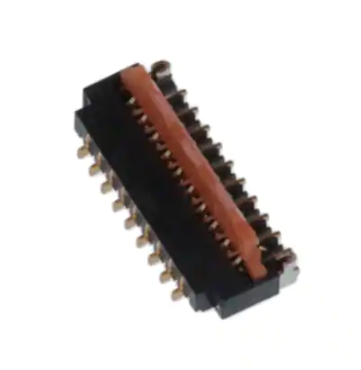
0.3mm Pitch, 1.0mm Height FPC Connector
May 2017 ③
�FH26 Series/0.3mm Pitch, 1.0mm Height FPC Connector
Features
1.0mm
1. Low- profile 0. 3mm pitch FPC
connector
Aug.1.2022 Copyright 2022 HIROSE ELECTRIC CO., LTD. All Rights Reserved.
Ultra- thin design, 1. 0mm height, 3. 2mm width for
space- saving design.
・ 30% reduction in PCB footprint
・ 40% reduction in weight
( Compared to our 0. 3mm pitch FH23 Series 51
position connector. )
3.2mm
[51pos.]
16.8mm
Solder tabs do no protrude
outside of the connector body
Achieve a height of 1. 0mm and mated depth of 3. 2mm.
2. Easy PCB Mounting
The leads are double sided and have a 0. 6mm
mounting lead pitch to simplify mounting.
3. No pattern prohibited area
on bottom of connector
( Overmolding design)
The bottom of this connector is fully molded to
eliminate contact exposure and remove any
restrictions to PCB patterning and design.
No exposed contacts on the bottom
of the connector
4. Superior Operability with Flip
Lock
The flip lock ( one- touch rotating ZIF mechanism)
is easier to operate and works with a light force.
A clear tactile click confirms the completion of
the mating process.
2
�FH26 Series/0.3mm Pitch, 1.0mm Height FPC Connector
5. Easy FPC insertion
The metal FPC insertion guides helps to make the
FPC insertion process easier. The housing also
has a damage- resistant design.
Actuator
Aug.1.2022 Copyright 2022 HIROSE ELECTRIC CO., LTD. All Rights Reserved.
FPC
FPC Insertion
Lock Completion
6. Compatible with standard
0. 2mm FPC Thickness
This connector accepts standard 0. 2mm thick
FPC. ( The proper FPC stiffener thickness
prevents FPC deformation and eases insertion
and mating. )
7. Pick & Place Mounting
Offered in tape and reel packaging that is
compatible with automatic machine mounting.
( 5, 000 pieces per reel)
8. Halogen- free
All materials and substances used to produce this
product comply with Halogen- free standards.
* Defined according to IEC61249- 2- 21
Br : 900ppm Max. , Cl : 900ppm Max. , Br+ Cl : 1, 500ppm Max.
9. Multiple packing options
The standard packaging is 5, 000 pieces per reel,
but it is also offered in a 500 piece reel. ( The
outer diameter of the reel will be φ180mm in this
case. )
3
�FH26 Series/0.3mm Pitch, 1.0mm Height FPC Connector
Product Specifications
Rated Current (Note 1)
0.2A
Operating Temperature (Note 2)
-55 to +85℃
Rated Voltage
30V AC/DC
Storage Temperature Range (Note 3)
-10 to +50℃
Operating Humidity Range
Relative humidity 90% Max.
(No condensation)
Storage Humidity Range
Recommended FPC
Thickness : = 0.2 ± 0.03mm Gold Plated
Item
Aug.1.2022 Copyright 2022 HIROSE ELECTRIC CO., LTD. All Rights Reserved.
Relative humidity 90% Max.
(No condensation)
Specification
Conditions
Insulation Resistance
50M Ω Min.
100V DC
Withstanding Voltage
No flashover or insulation breakdown.
90V AC for 1 min.
Contact Resistance
100m Ω Max.
Including FPC conductor resistance
1mA
Mating Durability (Insertion/
Withdrawal)
Contact resistance : 100m Ω Max.
No damage, cracks, or parts dislocation.
10 cycles
Vibration
No electrical discontinuity of 1μ s or more.
Contact resistance : 100m Ω Max.
No damage, cracks, or parts dislocation.
Frequency : 10 to 55 Hz,
single amplitude of 0.75mm,
10 cycles, 3 directions.
Shock
No electrical discontinuity of 1μ s. Min.
Contact resistance : 100m Ω Max.
No damage, cracks, or parts dislocation.
Acceleration of 981 m/s2,
6 ms duration, sine half-wave waveform,
3 cycles in each of the 3 axis
Humidity
(Steady State)
Contact resistance :100m Ω Max.
Insulation resistance : 50M Ω Min.
No affect on appearance or performance.
96 hours at temperature of 40 ± 2℃ and humidity of
90% to 95%.
Temperature Cycle
Contact resistance : 100m Ω Max.
Insulation resistance : 50M Ω Min.
No damage, cracks, or parts looseness.
Temperature : -55 ℃→ +15℃ to +35℃→ +85℃
→ +15℃ to +35℃
Time : 30 → 2 to 3 → 30 → 2 to 3 (Minutes)
5 cycles
Resistance to Soldering Heat
No deformation of components affecting
performance.
Reflow : At the recommended temperature profile
Manual soldering: 350℃ +/-10℃ for 5 ± 1 seconds
Note 1 : When passing the current through all of the contacts, use 70% of the rated current.
Note 2 : Includes temperature rise caused by current flow.
Note 3 : The term "storage" refers to products stored for long period of time prior to mounting and use. Operating temperature and humidity range
applies to mounted connectors in the non-energized state during storage, shipment and transportation.
4
�FH26 Series/0.3mm Pitch, 1.0mm Height FPC Connector
Materials / Finish
Part
Material
Insulator
Contacts
Remarks
LCP
Color : Black
UL94V-0
PA
FH26W Series : Light Brown
UL94HB
Gold Plated
-
Pure Tin Reflow Plated
-
Phosphor Bronze
Retention Tabs
Finish
Aug.1.2022 Copyright 2022 HIROSE ELECTRIC CO., LTD. All Rights Reserved.
Product Number Structure
Refer to the chart below when determining the product specifications from the product number.
Please select from the product numbers listed in this catalog when placing orders.
FH26W - 51S - 0.3 SHW (##)
❶
❷
❸
❹
❺
❶
Series Name
FH26W
❹
Termination Type
SHW : SMT Horizontal Staggered Mounting
Type
❷
No. of Pos.
13 to 71
❺
Specifications
❸
Contact Pitch
0.3mm
(60) : Gold Plating with Nickel Barrier,
5,000pcs per reel
(97) : Gold Plating with Nickel Barrier,
500pcs per reel
5
�FH26 Series/0.3mm Pitch, 1.0mm Height FPC Connector
Connector Dimensions
A
(0.12)
3.2
0.6
(1.25)
B
0.3
Number of Positions Indicator
(0.12)
C
(0.3)
0.6
1
Aug.1.2022 Copyright 2022 HIROSE ELECTRIC CO., LTD. All Rights Reserved.
##
0.5
0.3
3.2
(D : FPC Insertion Slot Dimension)
(Note 1)
0.1
E
Note 1 : The coplanarity of each terminal lead within specified dimension is 0.1mm Max.
Note 2 : Packaged on tape and reel only. Check packaging specification.
Note 3 : Please note a sink hole might be added for improvements. Black spots may appear on
the resin but this does not affect product performance.
Note 4 : After reflow, the terminal plating may change color, however this does not represent
a quality issue.
Note : Embossed tape reel packaging.
6
(Note 1)
0.1
�FH26 Series/0.3mm Pitch, 1.0mm Height FPC Connector
Aug.1.2022 Copyright 2022 HIROSE ELECTRIC CO., LTD. All Rights Reserved.
■ Connector Dimension Table
Unit : mm
Part No.
HRS No.
No. of Pos.
A
B
C
D
E
FH26W-13S-0.3SHW(##)
CL0580-2401-1-##
13
5.4
3.0
3.6
4.23
4.9
FH26W-15S-0.3SHW(##)
CL0580-2402-4-##
15
6.0
3.6
4.2
4.83
5.5
FH26W-17S-0.3SHW(##)
CL0580-2403-7-##
17
6.6
4.2
4.8
5.43
6.1
FH26W-19S-0.3SHW(##)
CL0580-2437-9-##
19
7.2
4.8
5.4
6.03
6.7
FH26W-21S-0.3SHW(##)
CL0580-2404-0-##
21
7.8
5.4
6.0
6.63
7.3
FH26W-23S-0.3SHW(##)
CL0580-2405-2-##
23
8.4
6.0
6.6
7.23
7.9
FH26W-25S-0.3SHW(##)
CL0580-2406-5-##
25
9.0
6.6
7.2
7.83
8.5
FH26W-27S-0.3SHW(##)
CL0580-2400-9-##
27
9.6
7.2
7.8
8.43
9.1
FH26W-29S-0.3SHW(##)
CL0580-2407-8-##
29
10.2
7.8
8.4
9.03
9.7
FH26W-31S-0.3SHW(##)
CL0580-2408-0-##
31
10.8
8.4
9.0
9.63
10.3
FH26W-33S-0.3SHW(##)
CL0580-2409-3-##
33
11.4
9.0
9.6
10.23
10.9
FH26W-35S-0.3SHW(##)
CL0580-2410-2-##
35
12.0
9.6
10.2
10.83
11.5
FH26W-37S-0.3SHW(##)
CL0580-2411-5-##
37
12.6
10.2
10.8
11.43
12.1
FH26W-39S-0.3SHW(##)
CL0580-2412-8-##
39
13.2
10.8
11.4
12.03
12.7
FH26W-41S-0.3SHW(##)
CL0580-2413-0-##
41
13.8
11.4
12.0
12.63
13.3
FH26W-45S-0.3SHW(##)
CL0580-2414-3-##
45
15.0
12.6
13.2
13.83
14.5
FH26W-51S-0.3SHW(##)
CL0580-2415-6-##
51
16.8
14.4
15.0
15.63
16.3
FH26W-57S-0.3SHW(##)
CL0580-2417-1-##
57
18.6
16.2
16.8
17.43
18.1
FH26W-61S-0.3SHW(##)
CL0580-2418-4-##
61
19.8
17.4
18.0
18.63
19.3
FH26W-71S-0.3SHW(##)
CL0580-2419-7-##
71
22.8
20.4
21.0
21.63
22.3
7
Purchase Unit
(60)
(97)
5,000pcs
per reel
500pcs
per reel
�FH26 Series/0.3mm Pitch, 1.0mm Height FPC Connector
(0.65 : Metal Mask)
0.3 ±0.03
(0.23 : Metal Mask)
(0.3 : Metal Mask)
0.4 ±0.05
0.6 ±0.05
C ±0.05
0.5 ±0.05
0.95 ±0.05
(0.7 : Metal Mask)
Connector
Outline
0.2 ±0.05
2.15 ±0.05
(0.2)
0.6 ±0.05
(0.23 : Metal Mask)
(0.45)
0.3 ±0.03
Recommended Metal Mask thickness : t=0.1
0.3 ±0.05
0.8 ±0.05
Recommended FPC Dimensions
Note 1 M
(0.5)
0.1±0.02
0.6±0.07
0.2±0.03
0.3+0.04
-0.03
(0.05)
B±0.03
(0.15)
0.6±0.07
Note : If the stiffener cannot be more that 3.5mm
due to the FPC design, set Dimension M to
a minimum of 0.5mm.
8
B
A
3.5 Min..(Stiffener)
(0.07)
(0.2)
(0.2)
0.3 +0.04
-0.03
2.25±0.1
0.3±0.02
H
2.5±0.3
.
2.1±0.1
ax
M
1.1±0.1
0.6±0.02
1±0.1
.2
0.3±0.07
(0.15)
0.3±0.1
R0
C±0.03
1.1±0.1
1±0.1
F±0.05
0.3±0.07
0±0.03
Detail H
(Lead plated 0.1 Max.)
*RELATIVE
POSITIONS
OF POINT-A dnd B
●
B ±0.05
(2.5)
Aug.1.2022 Copyright 2022 HIROSE ELECTRIC CO., LTD. All Rights Reserved.
(3.6)
0.65 ±0.05
(0.55 : Metal Mask)
Recommended PCB Mounting Pattern and Metal Mask Dimensions
�FH26 Series/0.3mm Pitch, 1.0mm Height FPC Connector
●
Recommended Land Pattern, Metal Mask and FPC Dimensions Table
Unit : mm
Aug.1.2022 Copyright 2022 HIROSE ELECTRIC CO., LTD. All Rights Reserved.
Part No.
HRS No.
No. of Pos.
B
C
F
FH26W-13S-0.3SHW(##)
CL0580-2401-1-##
13
3.0
3.6
4.2
FH26W-15S-0.3SHW(##)
CL0580-2402-4-##
15
3.6
4.2
4.8
FH26W-17S-0.3SHW(##)
CL0580-2403-7-##
17
4.2
4.8
5.4
FH26W-19S-0.3SHW(##)
CL0580-2437-9-##
19
4.8
5.4
6.0
FH26W-21S-0.3SHW(##)
CL0580-2404-0-##
21
5.4
6.0
6.6
FH26W-23S-0.3SHW(##)
CL0580-2405-2-##
23
6.0
6.6
7.2
FH26W-25S-0.3SHW(##)
CL0580-2406-5-##
25
6.6
7.2
7.8
FH26W-27S-0.3SHW(##)
CL0580-2400-9-##
27
7.2
7.8
8.4
FH26W-29S-0.3SHW(##)
CL0580-2407-8-##
29
7.8
8.4
9.0
FH26W-31S-0.3SHW(##)
CL0580-2408-0-##
31
8.4
9.0
9.6
FH26W-33S-0.3SHW(##)
CL0580-2409-3-##
33
9.0
9.6
10.2
FH26W-35S-0.3SHW(##)
CL0580-2410-2-##
35
9.6
10.2
10.8
FH26W-37S-0.3SHW(##)
CL0580-2411-5-##
37
10.2
10.8
11.4
FH26W-39S-0.3SHW(##)
CL0580-2412-8-##
39
10.8
11.4
12.0
FH26W-41S-0.3SHW(##)
CL0580-2413-0-##
41
11.4
12.0
12.6
FH26W-45S-0.3SHW(##)
CL0580-2414-3-##
45
12.6
13.2
13.8
FH26W-51S-0.3SHW(##)
CL0580-2415-6-##
51
14.4
15.0
15.6
FH26W-57S-0.3SHW(##)
CL0580-2417-1-##
57
16.2
16.8
17.4
FH26W-61S-0.3SHW(##)
CL0580-2418-4-##
61
17.4
18.0
18.6
FH26W-71S-0.3SHW(##)
CL0580-2419-7-##
71
20.4
21.0
21.6
9
�FH26 Series/0.3mm Pitch, 1.0mm Height FPC Connector
Packaging Specification
5 +0
1.
8±0.1
φ
4±0.1 2±0.15
(1.6)
(3.05)
(4.55)
(1.25)
Embossed Carrier Tape Dimensions (Tape Width 32mm Min.)
Unreeling Direction
(3.05)
(4.55)
1.5 +0.1
0
(1.25)
Flat surface,
for placement with
automatic equipment
Reel Dimensions
)
Unreeling Direction
(φ80.0)
(L : INSIDE)
(φ380.0)
●
1.7 +0.15
0
(K)
J±0.1
H±0.1
φ
1.
5
(0.3)
G±0.3
+0
0 .1
(1.6)
1.75±0.1
●
Flat surface,
for placement with
automatic equipment
(φ
13
.0
Aug.1.2022 Copyright 2022 HIROSE ELECTRIC CO., LTD. All Rights Reserved.
Unreeling Direction
G±0.3
(K)
J±0.1
(0.3)
1.75±0.1
Embossed Carrier Tape Dimensions (Tape Width 24mm Max.)
0 .1
●
(M : OUTSIDE)
End Section
Mounting Section
Lead Section (400mm Min.)
Connectors
Blank Section
(10 pockets Min.)
Embossed Carrier Tape
Blank Section
(10 pockets Min.)
10
Top Cover Tape
�FH26 Series/0.3mm Pitch, 1.0mm Height FPC Connector
■ Packaging Dimension Table
Aug.1.2022 Copyright 2022 HIROSE ELECTRIC CO., LTD. All Rights Reserved.
Part No.
HRS No.
Unit : mm
No. of Pos.
G
H
J
K
L
M
FH26W-13S-0.3SHW(##)
CL0580-2401-1-##
13
16.0
7.5
5.6
17.4
21.4
FH26W-15S-0.3SHW(##)
CL0580-2402-4-##
15
16.0
7.5
6.2
17.4
21.4
FH26W-17S-0.3SHW(##)
CL0580-2403-7-##
17
16.0
7.5
6.8
17.4
21.4
FH26W-19S-0.3SHW(##)
CL0580-2437-9-##
19
16.0
7.5
7.4
17.4
21.4
FH26W-21S-0.3SHW(##)
CL0580-2404-0-##
21
16.0
7.5
8.0
17.4
21.4
FH26W-23S-0.3SHW(##)
CL0580-2405-2-##
23
16.0
7.5
8.6
17.4
21.4
FH26W-25S-0.3SHW(##)
CL0580-2406-5-##
25
16.0
7.5
9.2
17.4
21.4
FH26W-27S-0.3SHW(##)
CL0580-2400-9-##
27
16.0
7.5
9.8
17.4
21.4
FH26W-29S-0.3SHW(##)
CL0580-2407-8-##
29
24.0
11.5
10.4
25.4
29.4
FH26W-31S-0.3SHW(##)
CL0580-2408-0-##
31
24.0
11.5
11.0
25.4
29.4
FH26W-33S-0.3SHW(##)
CL0580-2409-3-##
33
24.0
11.5
11.6
25.4
29.4
FH26W-35S-0.3SHW(##)
CL0580-2410-2-##
35
24.0
11.5
12.2
25.4
29.4
FH26W-37S-0.3SHW(##)
CL0580-2411-5-##
37
24.0
11.5
12.8
25.4
29.4
FH26W-39S-0.3SHW(##)
CL0580-2412-8-##
39
24.0
11.5
13.4
25.4
29.4
FH26W-41S-0.3SHW(##)
CL0580-2413-0-##
41
24.0
11.5
14.0
25.4
29.4
FH26W-45S-0.3SHW(##)
CL0580-2414-3-##
45
24.0
11.5
15.2
25.4
29.4
FH26W-51S-0.3SHW(##)
CL0580-2415-6-##
51
24.0
11.5
17.0
25.4
29.4
FH26W-57S-0.3SHW(##)
CL0580-2417-1-##
57
32.0
28.4
14.2
18.8
33.4
37.4
FH26W-61S-0.3SHW(##)
CL0580-2418-4-##
61
32.0
28.4
14.2
20.0
33.4
37.4
FH26W-71S-0.3SHW(##)
CL0580-2419-7-##
71
44.0
40.4
20.2
23.0
45.4
49.4
11
-
�FH26 Series/0.3mm Pitch, 1.0mm Height FPC Connector
Recommended FPC Construction
1. Using Single-sided FPC
Material Name
Covering film layer.
Cover adhesive
Surface treatment
Copper foil
Base adhesive
Base film
Material
Polyimide
Thickness (μm)
1 mil thick.
25
25
1μm to 5μm Nickel underplated
0.2μm Gold plated
Cu
3
1oz
35
Thermosetting adhesive
25
Polyimide
1 mil thick
25
Polyimide
3 mil thick
Aug.1.2022 Copyright 2022 HIROSE ELECTRIC CO., LTD. All Rights Reserved.
Reinforcement material adhesive Thermosetting adhesive
Stiffener
40
75
Total
203
2. Using Double-sided FPC
Material Name
Covering layer film
Cover adhesive
Surface treatment
Through-hole copper
Material
Polyimide
Thickness (μm)
1 mil thick
1μm to 5μm Nickel underplated
0.2μm Gold plated
Cu
Copper foil
Cu
Base adhesive
Thermosetting adhesive
1/2oz
Base film
Polyimide
Base adhesive
Thermosetting adhesive
Copper foil
Cu
Cover adhesive
Thermosetting adhesive
Covering layer film
Polyimide
1 mil thick
1/2oz
1 mil thick
Reinforcement material adhesive Thermosetting adhesive
Stiffener
Polyimide
1 mil thick
Total
Note : To prevent release of the FPC due to bending, use of double-sided FPC with copper foil on the back side is NOT RECOMMENDED.
3. Precautions
1. This specification is a recommendation for the construction of the FH26 Series FPC ( t= 0. 2±0. 03) .
2. For details about the construction, please contact FPC manufacturers.
12
25
25
3
15
18
18
25
18
18
25
25
25
25
197
�FH26 Series/0.3mm Pitch, 1.0mm Height FPC Connector
Operation and Precautions
HRS test conditions
250℃ Max.
250
Temperature
230℃
200
Reflow, IR/hot air
Environment :
Room air
Solder Composition :
Paste,
96.5%Sn/3.0%Ag/0.5%Cu
(Senju Metal Industry,
Co., Ltd.'s
Part Number: M705221CM5-32-10.5)
Test Board :
Glass epoxy
25mm × 50mm × 0.8mm thick
Land Dimensions :
0.3mm × 0.65mm,
0.3mm × 0.8mm
Metal Mask :
0.23 × 0.55 × 0.1mm thick,
0.23 × 0.65 × 0.1mm thick
200℃
150
150℃
(℃)
Aug.1.2022 Copyright 2022 HIROSE ELECTRIC CO., LTD. All Rights Reserved.
Solder Method :
100
50
25℃
0
Start
(60sec.)
90 sec. to 120 sec.
Preheating
60
The temperature profiles are based on the above
conditions.
In individual applications the actual temperature
may vary depending on solder paste type,
volume/thickness and board size/thickness.
Consult your solder paste and equipment
manufacturer for specific recommendations.
(60sec.)
Soldering
120
Time (Seconds)
13
�FH26 Series/0.3mm Pitch, 1.0mm Height FPC Connector
Operation and Precautions
[ Operation]
Aug.1.2022 Copyright 2022 HIROSE ELECTRIC CO., LTD. All Rights Reserved.
1. FPC insertion procedure.
① Lift the actuator upward to unlock. ( Lock release) The actuator flips open easily when operated with a finger.
② Fully insert the FPC in the connector parallel to mounting surface, with the exposed
conductive traces facing down.
FPC conductor
surface (Bottom side)
③ Rotate the actuator downward until firmly closed. If the FPC is not fully inserted or is extremely
misaligned remove the FPC as described in 2- ② . Reoperate starting from 1- ① .
Make sure to secure the connector during locking.
2. FPC Removal
① Lift up the actuator. Remove the FPC after releasing the lock.
14
�FH26 Series/0.3mm Pitch, 1.0mm Height FPC Connector
[ Precautions]
[ Precautions When Mounting to PCB ]
● Acceptable amount of PCB warpage
PCB warpage should be kept to a minimum. The maximum coplanarity of this connector is 0. 1mm, but excessive
warpage may result in solder failure.
● FPC Specifications
Stiffeners can be used to improve the rigidity of the FPC. We recommend using a glass epoxy with a thickness of 0. 3mm
or more.
● Load to the Connector
Do not apply any excessive force ( 0. 5N Max. ) or mate/ unmate the connectors until they are mounted, failure to
follow this precaution can lead to deformation or damage to the connectors. Inserting the FPC prior to mounting is not
recommended either.
[ Precautions for Handling the PCB After Mounting ]
● Applied force to the PCB
Do not place any excessive force on the PCB after connector mounting as this may damage the connectors. ( e. g. ,
When separating the PCB into multiple boards or installing fastening screws onto the PCB)
● PCB Bending
PCBs with a width of 100mm should not be bent more than 0. 5mm Max. ( Please refer to the
diagrams below. ) PCB bending places an extra load onto the connector and may lead to damage or malfunction.
Connector
100
0.5 Max.
PCB
Connector
0.5 Max.
Aug.1.2022 Copyright 2022 HIROSE ELECTRIC CO., LTD. All Rights Reserved.
This connector needs to be handled with care due to its thin, small design.
100
PCB
[ Precautions When Inserting or Coupling FPC ]
Pay attention to the following points when inserting FPC.
● Actuator Operation
① Do not apply excessive force when opening the actuator prior to FPC insertion.
When opening make sure that the force is applied only to the actuator itself. Avoid touching the contacts.
Actuator
Contact Deformation
Contact Deformation
15
�FH26 Series/0.3mm Pitch, 1.0mm Height FPC Connector
② Rotational Axis
Axis of rotation
Aug.1.2022 Copyright 2022 HIROSE ELECTRIC CO., LTD. All Rights Reserved.
③ The actuator is designed to rotate up to 135°so do not apply excessive force to rotate it further.
Applying excessive force may result in the lock lever coming off or damage to the connector.
135°
④ When operating the actuator, do so at the center portion.
⑤ As illustrated, do not attempt removal or repositioning of the actuator.
( Do not do any operation other than the axis rotation described in ② . )
16
�FH26 Series/0.3mm Pitch, 1.0mm Height FPC Connector
● FPC Insertion①
Aug.1.2022 Copyright 2022 HIROSE ELECTRIC CO., LTD. All Rights Reserved.
Perpendicular with
the connector
The FPC should be aligned parallel with the board surface and perpendicular with the connector
( as shown) , then completely inserted.
To assure correct electrical and mechanical connection do not insert the FPC
at an angle. Inserting the FPC at an angle may result in a short circuit due to
pitch misalignment, or the corners of the FPC may get caught and deform the contacts.
Since this is a ZIF connector with 0. 35mm effective mating length ( HRS recommended
FPC nominal size) , do not pull out the FPC after insertion when operating the actuator.
● FPC Insertion②
Do not insert the FPC at any angle from above.
As illustrated, angled insertion may result in FPC bending, pattern breakage or incomplete
mating resulting in conduction failure.
Note 1 : To avoid inserting the FPC at an angle, secure sufficient FPC insertion space at the time of board layout. Insertion will be
difficult when the FPC is too short.
Note 2 : Contact the FPC manufacturer for information about the bending specifications.
● Confirming Locking Status
When locked the actuator should be level with respect to the board surface as illustrated below.
Do not press against the actuator when is fully closed. Max force applied to the fully closed actuator
should not exceed 1N.
17
�FH26 Series/0.3mm Pitch, 1.0mm Height FPC Connector
[ Precautions for Routing the FPC after FPC Insertion]
● FPC Load
Do not apply force in excess of 0. 05N/ pin Max. in the upward direction ( as illustrated) .
Excessive force may result in the connector unlocking or FPC damage. Secure the FPC
when a continous load will be applied.
Do not bend the FPC too close to the actuator.
Aug.1.2022 Copyright 2022 HIROSE ELECTRIC CO., LTD. All Rights Reserved.
Load : 0.05N/pin Max.
[ FPC Removal]
Rotate the actuator to the open position ( maximum open angle of 135) . Carefully withdraw the FPC.
135°
[ Other Precautions] ]
● Hand Soldering Precautions
When hand soldering:
① Do not perform reflow or hand soldering with the FPC inserted in the connector.
② Do not apply excessive heat or touch the soldering iron anywhere other than the connector leads.
③ Do not use excessive amount of solder or flux compounds.
Operation of the actuator and contacts may be affected by excessive amounts of solder or flux
compounds. Applying too much solder on the retention tabs may hinder the rotation of the actuator
and result in connector damage.
While taking in consideration
Specifications mentioned in this catalog are reference values.
When considering to order or use this product, please confirm the " Drawing" and " Product Specifications" sheets.
Use an appropriate cable when using the connector in combination with cables.
If considering usage of a non- specified cable, please contact your sales representative.
If assembly process is done by jigs & tools which are not identified by Hirose assurance will not be given.
Please consult with your Hirose sales representative if you are planning to use the product for any of the following
applications. ( Automotive, medical, public infrastructure, aerospace/ defense, etc. )
Hirose will consider the validity of the warranty depending on the conditions.
2-6-3,Nakagawa Chuoh,Tsuzuki-Ku,Yokohama-Shi 224-8540,JAPAN
https://www.hirose.com
※ The contents of this catalog are current as of date of xx/ xxxx. Contents are subject to change without notice for the purpose of improvements.
18
�


 工商网监
湘ICP备2023018690号
工商网监
湘ICP备2023018690号
